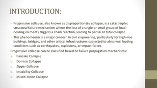
Progressive Collapse Analysis of RCC, Composite, and Hybrid SRC Structures
This M.Tech project focuses on studying and comparing how different structural systems behave when one of their critical columns fails unexpectedly, leading to what is known as progressive collapse. Progressive collapse is a condition where the failure of a single structural element causes a chain reaction, leading to partial or total collapse of the structure. This is an important consideration in modern high-rise design, especially after several real-world failures caused by accidental or extreme events such as explosions, design errors, or vehicle impacts.
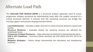
The main objective of this study was to analyse the performance of RCC, Composite, and Hybrid SRC structures under various column removal scenarios, to identify which system provides better safety, redundancy, and resistance to collapse. The analysis was performed using the Alternate Load Path Method (ALPM) as per GSA 2003 Guidelines, which is one of the most recognized standards for progressive collapse assessment.
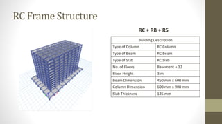
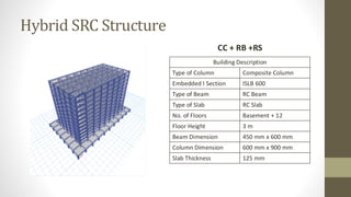
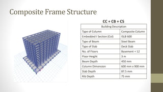
A G+12 storey building with a grid spacing of 6 m × 5 m was modelled in ETABS. Three separate structural models were created:
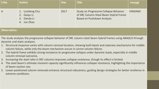
1. RCC Structure – conventional reinforced concrete columns, beams, and slabs.
2. Composite Structure – steel columns and beams combined with reinforced concrete slab.
3. Hybrid SRC Structure – composite columns (encased steel) with reinforced concrete beams and slabs.
Each of these models was tested for four different column removal cases to simulate possible local failures:
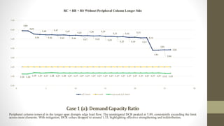
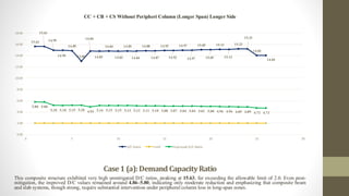
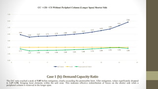
Case 1: Periphery column removal along the long span.
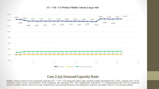
Case 2: Middle column removal.
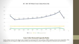
Case 3: Corner column removal.
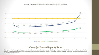
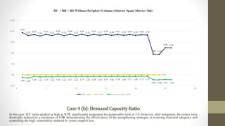
Case 4: Periphery column removal along the short span.
Both long span (a) and short span (b) variations were considered to evaluate the effect of geometry on load redistribution. The load combination 2(DL + 0.25LL) was used to simulate the sudden removal of a column, as recommended by GSA.
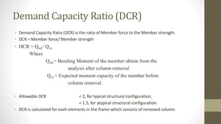
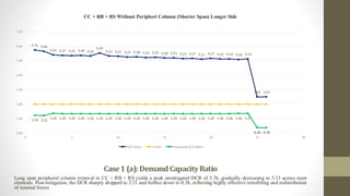
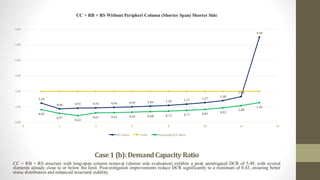
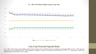
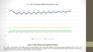
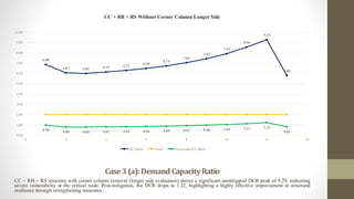
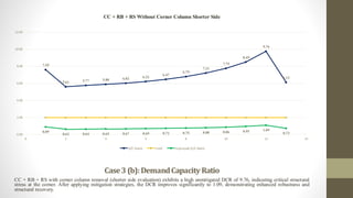
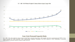
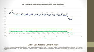
The Demand–Capacity Ratio (DCR) was calculated for every beam and column to determine the extent of overstressing in the structure after column removal. A DCR value greater than 2.0 indicated potential failure, while values below 1.0 were considered safe.
The results showed that the Composite structure performed the best, with the lowest DCR values and higher energy absorption capacity due to the ductility of steel. The Hybrid SRC structure also performed well, offering a balance between the stiffness of concrete and the ductility of steel. The RCC structure, however, showed higher DCR values, especially around the region of column removal, indicating greater vulnerability to progressive collapse.
Overall, the study clearly demonstrates that Composite and Hybrid SRC systems are more resistant to progressive collapse compared to conventional RCC frames. These systems provide better redundancy, improved stiffness, and superior load redistribution during accidental column failures.


![➢ Model Development
• RC Frame Structure
• Hybrid SRC Structure (RC Column- Steel Beam & Deck)
• Composite Frame Structure
➢ Linear Static Analysis
• Perform Linear Static Analysis
• Analyse Structures under Gravity Load-[DL+LL] & [2(DL+0.25LL)]
➢ Progressive Collapse Analysis (Without Mitigation)
• Implement GSA column removal method
• Evaluate Structural failure under gravity loads
• Identify critical failure points
➢ Mitigation Strategies Implementation
• Introduce bracings & structural integrity elements
• Improve lateral stability and load distribution
➢ Progressive Collapse Analysis (With Mitigation)
• Reassess structures using GSA guidelines
• Evaluate impact of mitigation strategies on collapse resistance
• Compare improved DC ratios with unmitigated results
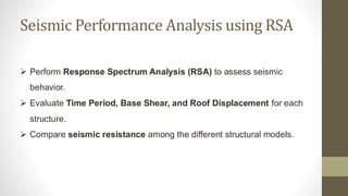
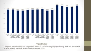
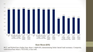
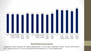
➢ Response Spectrum Analysis (RSA) for Seismic Performance
• Perform Response Spectrum Analysis (RSA) for seismic response
• Analyze Time Period, Base Shear & Roof Displacement
• Compare seismic resistance among structural models
➢ Comparative Evaluation & Conclusion
• Compare results for all models under both progressive collapse and seismic loads
• Identify most resilient structure in both scenarios
• Provide recommendations for structural optimization and practical applications](https://image.slidesharecdn.com/progressivecollapse-shaikfaraazahmed-251111182752-e830bb71/85/Progressive-Collapse-21011D2022-VB-pdf-21-320.jpg)


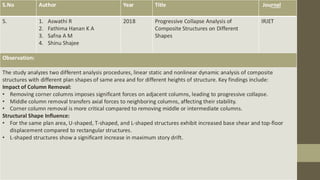
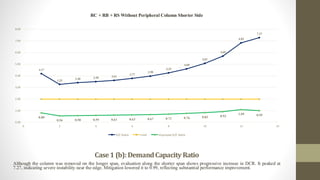
![Case 1 (a): Removal of Periphery Column
(Long Side Periphery) [RC + RB + RC]
Sl.No. Beam No BM Before BM After D/C Ratio
1 B1 55.04 324.39 5.89
2 B2 55.09 324.39 5.89
3 B3 56.53 312.95 5.54
4 B4 57.11 312.95 5.48
5 B5 57.27 312.73 5.46
6 B6 57.11 312.57 5.47
7 B7 57.27 310.63 5.42
8 B8 57.13 311.48 5.45
9 B9 57.29 309.18 5.40
10 B10 57.22 310.03 5.42
11 B11 57.27 307.44 5.37
12 B12 57.27 308.29 5.38
13 B13 57.26 305.37 5.33
14 B14 57.27 306.23 5.35
15 B15 57.26 302.98 5.29
16 B16 57.27 303.83 5.31
17 B17 57.24 300.24 5.25
18 B18 57.25 301.08 5.26
19 B19 57.24 297.18 5.19
20 B20 57.22 297.99 5.21
21 B21 57.14 293.14 5.13
22 B22 57.17 293.84 5.14
23 B23 56.96 217.21 3.81
24 B24 57 217.43 3.81
25 B25 56.54 217.21 3.84
26 B26 56.36 217.43 3.86
LONG SIDE SPAN
Elevation 2
Without Mitigation](https://image.slidesharecdn.com/progressivecollapse-shaikfaraazahmed-251111182752-e830bb71/85/Progressive-Collapse-21011D2022-VB-pdf-27-320.jpg)
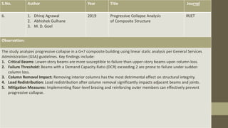
![Case 1 (b): Removal of Periphery Column
(Long Side Periphery) [RC + RB +RS]
SHORT SIDE SPAN
Elevation F
Without Mitigation
Sl.No. Beam No BM Before BM After D/C Ratio
1 B1 91.93 111.5 3.35
2 B2 122.4 103.29 2.45
3 B3 116.84 104.62 2.56
4 B4 114.47 104.58 2.63
5 B5 111.48 104.72 2.72
6 B6 107.71 104.9 2.85
7 B7 103.15 105.11 3.00
8 B8 97.77 105.35 3.20
9 B9 91.53 105.64 3.47
10 B10 84.39 105.96 3.82
11 B11 76.44 106.34 4.29
12 B12 65.07 107.17 5.12
13 B13 69.67 386.15 6.01](https://image.slidesharecdn.com/progressivecollapse-shaikfaraazahmed-251111182752-e830bb71/85/Progressive-Collapse-21011D2022-VB-pdf-28-320.jpg)
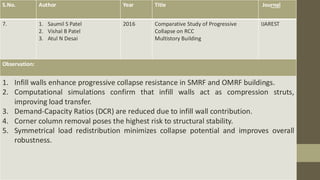
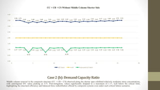
![Case 2 (a): Removal of Periphery Column
(Short Side Periphery) [RC + RB + RC]
LONG SIDE SPAN
Elevation 5
Without Mitigation
Sl.No. Beam No BM Before BM After D/C Ratio
1 B1 111.64 308 2.76
2 B2 130.93 299.62 2.29
3 B3 130.51 299.68 2.30
4 B4 128.08 301.45 2.35
5 B5 125.16 303.7 2.43
6 B6 121.68 306.63 2.52
7 B7 117.52 309.55 2.63
8 B8 112.63 313.3 2.78
9 B9 106.97 317.63 2.97
10 B10 100.52 322.55 3.21
11 B11 93.19 328.23 3.52
12 B12 84.89 333.25 3.93
13 B13 85.09 418.52 4.92](https://image.slidesharecdn.com/progressivecollapse-shaikfaraazahmed-251111182752-e830bb71/85/Progressive-Collapse-21011D2022-VB-pdf-29-320.jpg)
![Case 2 (b): Removal of Periphery Column
(Short Side Periphery) [RC + RB +RS]
SHORT SIDE SPAN
Elevation J Without Mitigation
Sl.No. Beam No BM Before BM After D/C Ratio
1 B1 34.56 336.94 9.75
2 B2 36.46 337.1 9.25
3 B3 34.31 323.03 9.42
4 B4 35.28 323.08 9.16
5 B5 34.5 325.13 9.42
6 B6 35.2 325.16 9.24
7 B7 34.17 324.21 9.49
8 B8 35.19 324.29 9.22
9 B9 34.12 323.39 9.48
10 B10 35.09 323.48 9.22
11 B11 34.06 322.35 9.46
12 B12 34.97 322.48 9.22
13 B13 33.99 321.12 9.45
14 B14 34.67 321.27 9.27
15 B15 33.82 319.68 9.45
16 B16 34.48 319.86 9.28
17 B17 33.77 318.02 9.42
18 B18 34.25 318.23 9.29
19 B19 33.63 316.1 9.40
20 B20 34.06 316.34 9.29
21 B21 33.48 314.12 9.38
22 B22 33.63 314.39 9.35
23 B23 53.58 310.86 5.80
24 B24 53.86 311.09 5.78
25 B25 53.58 374.46 6.99
26 B26 53.86 374.6 6.96](https://image.slidesharecdn.com/progressivecollapse-shaikfaraazahmed-251111182752-e830bb71/85/Progressive-Collapse-21011D2022-VB-pdf-30-320.jpg)
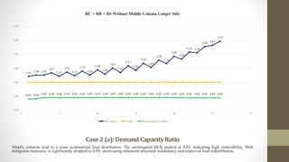
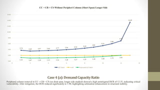
![Case 3 (a): Removal of Middle Column
[RC + RB + RC]
LONG SIDE SPAN
Elevation 5
Without Mitigation
Sl.No. Beam No BM Before BM After D/C Ratio
1 B1 66.24 159.44 2.41
2 B2 66.35 166 2.50
3 B3 66.1 165.72 2.51
4 B4 66.15 176.64 2.67
5 B5 66.95 162.94 2.43
6 B6 65.93 179.03 2.72
7 B7 65.97 162.85 2.47
8 B8 65.95 183.82 2.79
9 B9 65.99 165.1 2.50
10 B10 65.98 190.24 2.88
11 B11 66 170.07 2.58
12 B12 65.99 198.59 3.01
13 B13 66.01 177.85 2.69
14 B14 66 208.96 3.17
15 B15 66.02 188.56 2.86
16 B16 66.02 221.54 3.36
17 B17 66.04 201.43 3.05
18 B18 66.04 236.55 3.58
19 B19 66.08 219.83 3.33
20 B20 66.08 254.27 3.85
21 B21 66.08 241.65 3.66
22 B22 66.08 275.05 4.16
23 B23 66.02 270.93 4.10
24 B24 66.02 299.92 4.54
25 B25 66.05 306.78 4.64
26 B26 66.01 325.64 4.93](https://image.slidesharecdn.com/progressivecollapse-shaikfaraazahmed-251111182752-e830bb71/85/Progressive-Collapse-21011D2022-VB-pdf-31-320.jpg)
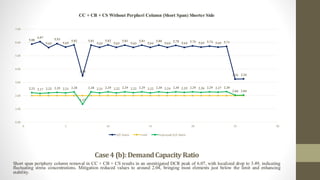
![Case 3 (b): Removal of Middle Column
[RC + RB +RS]
SHORT SIDE SPAN
Elevation J Without Mitigation
Sl.No. Beam No BM Before BM After D/C Ratio
1 B1 50.5 182.64 3.62
2 B2 53.34 181.47 3.40
3 B3 50.04 177.43 3.55
4 B4 51.57 175.44 3.40
5 B5 49.89 178.59 3.58
6 B6 51.54 176.1 3.42
7 B7 49.92 179.04 3.59
8 B8 51.51 176.2 3.42
9 B9 49.87 170.57 3.42
10 B10 51.39 176.43 3.43
11 B11 49.83 180.04 3.61
12 B12 51.25 176.69 3.45
13 B13 49.77 180.5 3.63
14 B14 51.09 177.02 3.46
15 B15 49.71 180.97 3.64
16 B16 50.89 177.42 3.49
17 B17 49.64 181.45 3.66
18 B18 50.87 177.91 3.50
19 B19 49.56 181.96 3.67
20 B20 50.4 178.48 3.54
21 B21 49.6 182.5 3.68
22 B22 50.16 179.17 3.57
23 B23 49.39 182.78 3.70
24 B24 49.63 179.83 3.62
25 B25 49.28 183.31 3.72
26 B26 49.69 181.38 3.65](https://image.slidesharecdn.com/progressivecollapse-shaikfaraazahmed-251111182752-e830bb71/85/Progressive-Collapse-21011D2022-VB-pdf-32-320.jpg)
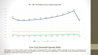
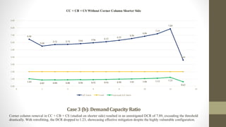
![Case 4 (a): Removal of Corner Column
[RC + RB + RC]
LONG SIDE SPAN
Elevation 5
Without Mitigation
Sl.No. Beam No BM Before BM After D/C Ratio
1 B1 76.46 519.87 6.80
2 B2 90.16 536.13 5.95
3 B3 90.4 533.63 5.90
4 B4 88.38 534.05 6.04
5 B5 86.13 534.15 6.20
6 B6 83.56 534.46 6.40
7 B7 80.51 534.84 6.64
8 B8 76.93 535.29 6.96
9 B9 72.82 535.86 7.36
10 B10 68.13 536.45 7.87
11 B11 62.88 537.37 8.55
12 B12 57.76 539.28 9.34
13 B13 87.51 519.58 5.94](https://image.slidesharecdn.com/progressivecollapse-shaikfaraazahmed-251111182752-e830bb71/85/Progressive-Collapse-21011D2022-VB-pdf-33-320.jpg)
![Case 4 (b): Removal of Corner Column
[RC + RB +RS]
SHORT SIDE SPAN
Elevation J Without Mitigation
Sl.No. Beam No BM Before BM After D/C Ratio
1 B1 64.53 476.18 7.38
2 B2 88.81 474.08 5.34
3 B3 84.54 474.55 5.61
4 B4 82.87 474.39 5.72
5 B5 80.85 474.36 5.87
6 B6 78.24 474.13 6.06
7 B7 75.7 473.85 6.26
8 B8 73.33 473.51 6.46
9 B9 67.02 473.11 7.06
10 B10 62.09 472.63 7.61
11 B11 56.39 471.89 8.37
12 B12 48.68 469.75 9.65
13 B13 71.27 440.78 6.18](https://image.slidesharecdn.com/progressivecollapse-shaikfaraazahmed-251111182752-e830bb71/85/Progressive-Collapse-21011D2022-VB-pdf-34-320.jpg)

![Case 1 (a): Removal of Periphery Column
(Long Side Periphery) [RC + RB + RC]
LONG SIDE SPAN
Elevation 2
With Mitigation
Sl.No. Beam No BM Before BM After D/C Ratio
1 B1 55.04 69.51 1.26
2 B2 55.09 69.51 1.26
3 B3 56.53 78.33 1.39
4 B4 57.11 78.33 1.37
5 B5 57.27 78.56 1.37
6 B6 57.11 78.63 1.38
7 B7 57.27 78.51 1.37
8 B8 57.13 78.59 1.38
9 B9 57.29 78.46 1.37
10 B10 57.22 78.53 1.37
11 B11 57.27 78.43 1.37
12 B12 57.27 78.51 1.37
13 B13 57.26 78.4 1.37
14 B14 57.27 78.48 1.37
15 B15 57.26 78.36 1.37
16 B16 57.27 78.44 1.37
17 B17 57.24 78.31 1.37
18 B18 57.25 78.4 1.37
19 B19 57.24 78.28 1.37
20 B20 57.22 78.37 1.37
21 B21 57.14 78.26 1.37
22 B22 57.17 78.35 1.37
23 B23 56.96 78.17 1.37
24 B24 57 78.25 1.37
25 B25 56.54 74.79 1.32
26 B26 56.36 74.88 1.33](https://image.slidesharecdn.com/progressivecollapse-shaikfaraazahmed-251111182752-e830bb71/85/Progressive-Collapse-21011D2022-VB-pdf-36-320.jpg)
![Case 1 (b): Removal of Periphery Column
(Long Side Periphery) [RC + RB +RS]
SHORT SIDE SPAN
Elevation F
With Mitigation
Sl.No. Beam No BM Before BM After D/C Ratio
1 B1 91.93 73.84 0.80
2 B2 122.4 67.94 0.56
3 B3 116.84 67.67 0.58
4 B4 114.47 67.91 0.59
5 B5 111.48 68.14 0.61
6 B6 107.71 68.38 0.63
7 B7 103.15 68.67 0.67
8 B8 97.77 69 0.71
9 B9 91.53 69.39 0.76
10 B10 84.39 69.81 0.83
11 B11 76.44 70.24 0.92
12 B12 65.07 70.85 1.09
13 B13 69.67 69.32 0.99](https://image.slidesharecdn.com/progressivecollapse-shaikfaraazahmed-251111182752-e830bb71/85/Progressive-Collapse-21011D2022-VB-pdf-37-320.jpg)
![Case 2 (a): Removal of Periphery Column
(Short Side Periphery) [RC + RB + RC]
LONG SIDE SPAN
Elevation 5
With Mitigation
Sl.No. Beam No BM Before BM After D/C Ratio
1 B1 111.64 73.56 0.66
2 B2 130.93 70.24 0.54
3 B3 130.51 70.08 0.54
4 B4 128.08 70.23 0.55
5 B5 125.16 70.38 0.56
6 B6 121.68 70.55 0.58
7 B7 117.52 70.75 0.60
8 B8 112.63 70.99 0.63
9 B9 106.97 71.27 0.67
10 B10 100.52 71.58 0.71
11 B11 93.19 71.95 0.77
12 B12 84.89 71.28 0.84
13 B13 85.09 89.79 1.06](https://image.slidesharecdn.com/progressivecollapse-shaikfaraazahmed-251111182752-e830bb71/85/Progressive-Collapse-21011D2022-VB-pdf-38-320.jpg)
![Case 2 (b): Removal of Periphery Column
(Short Side Periphery) [RC + RB +RS]
SHORT SIDE SPAN
Elevation J
With Mitigation
Sl.No. Beam No BM Before BM After D/C Ratio
1 B1 34.56 51.68 1.50
2 B2 36.46 51.74 1.42
3 B3 34.31 56.59 1.65
4 B4 35.28 56.65 1.61
5 B5 34.5 56.83 1.65
6 B6 35.2 56.9 1.62
7 B7 34.17 56.88 1.66
8 B8 35.19 56.93 1.62
9 B9 34.12 56.94 1.67
10 B10 35.09 57 1.62
11 B11 34.06 57.04 1.67
12 B12 34.97 57.1 1.63
13 B13 33.99 57.14 1.68
14 B14 34.67 57.21 1.65
15 B15 33.82 57.27 1.69
16 B16 34.48 57.34 1.66
17 B17 33.77 57.42 1.70
18 B18 34.25 57.49 1.68
19 B19 33.63 57.6 1.71
20 B20 34.06 57.67 1.69
21 B21 33.48 57.82 1.73
22 B22 33.63 57.89 1.72
23 B23 53.58 58.05 1.08
24 B24 53.86 58.11 1.08
25 B25 53.58 59.09 1.10
26 B26 53.86 59.13 1.10](https://image.slidesharecdn.com/progressivecollapse-shaikfaraazahmed-251111182752-e830bb71/85/Progressive-Collapse-21011D2022-VB-pdf-39-320.jpg)
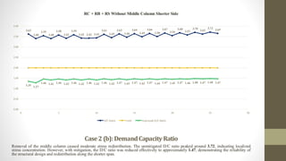
![Case 3 (a): Removal of Middle Column
[RC + RB + RC]
LONG SIDE SPAN
Elevation 5
With Mitigation
Sl.No. Beam No BM Before BM After D/C Ratio
1 B1 66.24 53.35 0.81
2 B2 66.35 53.37 0.80
3 B3 66.1 58.87 0.89
4 B4 66.15 58.84 0.89
5 B5 66.95 59.09 0.88
6 B6 65.93 59.04 0.90
7 B7 65.97 59.05 0.90
8 B8 65.95 59 0.89
9 B9 65.99 59.01 0.89
10 B10 65.98 58.97 0.89
11 B11 66 58.98 0.89
12 B12 65.99 58.94 0.89
13 B13 66.01 58.95 0.89
14 B14 66 58.91 0.89
15 B15 66.02 58.91 0.89
16 B16 66.02 58.88 0.89
17 B17 66.04 58.86 0.89
18 B18 66.04 58.83 0.89
19 B19 66.08 58.8 0.89
20 B20 66.08 58.78 0.89
21 B21 66.08 58.73 0.89
22 B22 66.08 58.71 0.89
23 B23 66.02 58.66 0.89
24 B24 66.02 58.63 0.89
25 B25 66.05 58.67 0.89
26 B26 66.01 58.66 0.89](https://image.slidesharecdn.com/progressivecollapse-shaikfaraazahmed-251111182752-e830bb71/85/Progressive-Collapse-21011D2022-VB-pdf-40-320.jpg)
![Case 3 (b): Removal of Middle Column
[RC + RB +RS]
SHORT SIDE SPAN
Elevation J With Mitigation
Sl.No. Beam No BM Before BM After D/C Ratio
1 B1 50.5 67.95 1.35
2 B2 53.34 67.96 1.27
3 B3 50.04 72.82 1.46
4 B4 51.57 72.84 1.41
5 B5 49.89 72.96 1.46
6 B6 51.54 73.01 1.42
7 B7 49.92 72.96 1.46
8 B8 51.51 72.99 1.42
9 B9 49.87 72.96 1.46
10 B10 51.39 72.99 1.42
11 B11 49.83 72.96 1.46
12 B12 51.25 72.99 1.42
13 B13 49.77 72.97 1.47
14 B14 51.09 73 1.43
15 B15 49.71 72.98 1.47
16 B16 50.89 73.01 1.43
17 B17 49.64 72.98 1.47
18 B18 50.87 73.02 1.44
19 B19 49.56 73 1.47
20 B20 50.4 73.04 1.45
21 B21 49.6 73.01 1.47
22 B22 50.16 73.05 1.46
23 B23 49.39 73.03 1.48
24 B24 49.63 73.07 1.47
25 B25 49.28 73.14 1.48
26 B26 49.69 73.17 1.47](https://image.slidesharecdn.com/progressivecollapse-shaikfaraazahmed-251111182752-e830bb71/85/Progressive-Collapse-21011D2022-VB-pdf-41-320.jpg)
![Case 4 (a): Removal of Corner Column
[RC + RB + RC]
LONG SIDE SPAN
Elevation 5
With Mitigation
Sl.No. Beam No BM Before BM After D/C Ratio
1 B1 76.46 69.88 0.91
2 B2 90.16 66.46 0.74
3 B3 90.4 66.37 0.73
4 B4 88.38 66.37 0.75
5 B5 86.13 66.37 0.77
6 B6 83.56 66.36 0.79
7 B7 80.51 66.35 0.82
8 B8 76.93 66.34 0.86
9 B9 72.82 66.32 0.91
10 B10 68.13 66.3 0.97
11 B11 62.88 66.31 1.05
12 B12 57.76 66.31 1.15
13 B13 87.51 68.86 0.79](https://image.slidesharecdn.com/progressivecollapse-shaikfaraazahmed-251111182752-e830bb71/85/Progressive-Collapse-21011D2022-VB-pdf-42-320.jpg)
![Case 4 (b): Removal of Corner Column
[RC + RB +RS]
SHORT SIDE SPAN
Elevation J With Mitigation
Sl.No. Beam No BM Before BM After D/C Ratio
1 B1 64.53 55.05 0.85
2 B2 88.81 52.17 0.59
3 B3 84.54 52.67 0.62
4 B4 82.87 52.65 0.64
5 B5 80.85 52.65 0.65
6 B6 78.24 52.65 0.67
7 B7 75.7 52.65 0.70
8 B8 73.33 52.65 0.72
9 B9 67.02 52.65 0.79
10 B10 62.09 52.63 0.85
11 B11 56.39 52.69 0.93
12 B12 48.68 52.78 1.08
13 B13 71.27 35.52 0.50](https://image.slidesharecdn.com/progressivecollapse-shaikfaraazahmed-251111182752-e830bb71/85/Progressive-Collapse-21011D2022-VB-pdf-43-320.jpg)


![Case 1 (a): Removal of Periphery Column
(Long Side Periphery) [CC + RB + RC]
LONG SIDE SPAN
Elevation 2
Without Mitigation
Sl.No. Beam No BM Before BM After D/C Ratio
1 B1 55.95 322.03 5.76
2 B2 56.96 322.65 5.66
3 B3 57.42 310.57 5.41
4 B4 57.99 311.35 5.37
5 B5 58.14 311.31 5.35
6 B6 58.01 312.14 5.38
7 B7 58.16 310.19 5.33
8 B8 58.1 3111.03 53.55
9 B9 58.13 309.77 5.33
10 B10 58.14 308.62 5.31
11 B11 58.13 306.1 5.27
12 B12 58.15 306.97 5.28
13 B13 58.13 304.16 5.23
14 B14 58.14 305.01 5.25
15 B15 58.11 301.89 5.20
16 B16 58.12 302.74 5.21
17 B17 58.07 299.3 5.15
18 B18 58.09 300.14 5.17
19 B19 57.99 296.3 5.11
20 B20 58.03 300.14 5.17
21 B21 57.8 296.41 5.13
22 B22 57.84 297.22 5.14
23 B23 57.36 292.57 5.10
24 B24 57.18 293.26 5.13
25 B25 86.61 217.7 2.51
26 B26 86.67 217.91 2.51](https://image.slidesharecdn.com/progressivecollapse-shaikfaraazahmed-251111182752-e830bb71/85/Progressive-Collapse-21011D2022-VB-pdf-55-320.jpg)
![Case 1 (b): Removal of Periphery Column
(Long Side Periphery) [CC + RB +RS]
SHORT SIDE SPAN
Elevation F
Without Mitigation
Sl.No. Beam No BM Before BM After D/C Ratio
1 B1 90.1 111.53 1.24
2 B2 119.76 103.45 0.86
3 B3 114.37 104.75 0.92
4 B4 112.11 104.71 0.93
5 B5 109.26 104.86 0.96
6 B6 105.65 105.02 0.99
7 B7 101.3 105.21 1.04
8 B8 96.18 105.44 1.10
9 B9 90.24 105.71 1.17
10 B10 83.45 106.02 1.27
11 B11 75.91 106.37 1.40
12 B12 64.94 107.28 1.65
13 B13 70.14 384.78 5.49](https://image.slidesharecdn.com/progressivecollapse-shaikfaraazahmed-251111182752-e830bb71/85/Progressive-Collapse-21011D2022-VB-pdf-56-320.jpg)
![Case 2 (a): Removal of Periphery Column
(Short Side Periphery) [CC + RB + RC]
LONG SIDE SPAN
Elevation 5
Without Mitigation
Sl.No. Beam No BM Before BM After D/C Ratio
1 B1 112.07 311.22 2.78
2 B2 130.25 302.94 2.33
3 B3 130.02 303.05 2.33
4 B4 127.72 304.65 2.39
5 B5 124.72 306.77 2.46
6 B6 121.58 309.29 2.54
7 B7 117.6 312.3 2.66
8 B8 112.93 315.91 2.80
9 B9 107.54 319.86 2.97
10 B10 101.4 324.46 3.20
11 B11 94.44 329.8 3.49
12 B12 86.61 334.36 3.86
13 B13 86.95 419.37 4.82](https://image.slidesharecdn.com/progressivecollapse-shaikfaraazahmed-251111182752-e830bb71/85/Progressive-Collapse-21011D2022-VB-pdf-57-320.jpg)
![Case 2 (b): Removal of Periphery Column
(Short Side Periphery) [CC + RB +RS]
SHORT SIDE SPAN
Elevation J Without Mitigation
Sl.No. Beam No BM Before BM After D/C Ratio
1 B1 41.08 335.45 8.17
2 B2 38.24 335.65 8.78
3 B3 42.41 321.78 7.59
4 B4 42.15 321.88 7.64
5 B5 42.98 323.84 7.53
6 B6 42.2 323.94 7.68
7 B7 43.07 322.968 7.50
8 B8 41.51 323.12 7.78
9 B9 43.11 322.21 7.47
10 B10 41.28 3222.36 78.06
11 B11 43.1 321.23 7.45
12 B12 40.98 321.41 7.84
13 B13 43.08 320.085 7.43
14 B14 40.64 320.27 7.88
15 B15 43.07 318.73 7.40
16 B16 40.25 318.94 7.92
17 B17 43.05 317.17 7.37
18 B18 39.83 317.42 7.97
19 B19 43.02 315.37 7.33
20 B20 40.25 315.64 7.84
21 B21 42.88 313.53 7.31
22 B22 40.91 313.82 7.67
23 B23 42.58 310.44 7.29
24 B24 40.86 310.64 7.60
25 B25 63.58 374.39 5.89
26 B26 62.9 374.55 5.95](https://image.slidesharecdn.com/progressivecollapse-shaikfaraazahmed-251111182752-e830bb71/85/Progressive-Collapse-21011D2022-VB-pdf-58-320.jpg)
![Case 3 (a): Removal of Middle Column
[CC + RB + RC]
LONG SIDE SPAN
Elevation 5
Without Mitigation
Sl.No. Beam No BM Before BM After D/C Ratio
1 B1 77.62 228.88 2.95
2 B2 78.98 228.93 2.90
3 B3 78.26 215 2.75
4 B4 79.02 215.05 2.72
5 B5 79.02 216.73 2.74
6 B6 78.83 216.8 2.75
7 B7 79.03 216.14 2.73
8 B8 78.89 216.2 2.74
9 B9 79.06 215.68 2.73
10 B10 78.99 215.75 2.73
11 B11 79.17 215.06 2.72
12 B12 79.11 215.13 2.72
13 B13 79.29 214.31 2.70
14 B14 79.23 214.39 2.71
15 B15 79.4 213.4 2.69
16 B16 79.36 213.48 2.69
17 B17 79.53 212.33 2.67
18 B18 79.49 212.41 2.67
19 B19 79.63 211.05 2.65
20 B20 79.62 211.14 2.65
21 B21 79.66 209.67 2.63
22 B22 79.7 209.67 2.63
23 B23 79.68 207.57 2.61
24 B24 79.47 207.66 2.61
25 B25 79.09 207.7 2.63
26 B26 79 207.76 2.63](https://image.slidesharecdn.com/progressivecollapse-shaikfaraazahmed-251111182752-e830bb71/85/Progressive-Collapse-21011D2022-VB-pdf-59-320.jpg)
![Case 3 (b): Removal of Middle Column
[CC + RB +RS]
SHORT SIDE SPAN
Elevation J Without Mitigation
Sl.No. Beam No BM Before BM After D/C Ratio
1 B1 57.14 362.58 6.35
2 B2 56.65 361.74 6.39
3 B3 58.07 352.53 6.07
4 B4 64.08 351.09 5.48
5 B5 58.59 353.76 6.04
6 B6 64.56 352.18 5.46
7 B7 58.62 353.9 6.04
8 B8 64.07 352.4 5.50
9 B9 58.62 354.29 6.04
10 B10 63.78 352.86 5.53
11 B11 58.6 354.73 6.05
12 B12 63.33 353.39 5.58
13 B13 58.56 355.28 6.07
14 B14 62.8 354.05 5.64
15 B15 58.51 355.94 6.08
16 B16 62.2 354.85 5.70
17 B17 58.44 356.75 6.10
18 B18 61.56 355.8 5.78
19 B19 58.36 357.73 6.13
20 B20 60.94 356.94 5.86
21 B21 58.23 358.91 6.16
22 B22 60 358.3 5.97
23 B23 58.14 360.07 6.19
24 B24 60.14 359.61 5.98
25 B25 57.93 362.75 6.26
26 B26 58.14 362.54 6.24](https://image.slidesharecdn.com/progressivecollapse-shaikfaraazahmed-251111182752-e830bb71/85/Progressive-Collapse-21011D2022-VB-pdf-60-320.jpg)
![Case 4 (a): Removal of Corner Column
[CC + RB + RC]
LONG SIDE SPAN
Elevation 5
Without Mitigation
Sl.No. Beam No BM Before BM After D/C Ratio
1 B1 75.55 519.8 6.88
2 B2 88.37 536.26 6.07
3 B3 88.7 533.64 6.02
4 B4 86.81 534.08 6.15
5 B5 84.67 534.18 6.31
6 B6 82.24 534.49 6.50
7 B7 79.35 534.86 6.74
8 B8 75.98 535.31 7.05
9 B9 72.11 535.84 7.43
10 B10 67.72 536.46 7.92
11 B11 62.77 537.36 8.56
12 B12 58.03 539.23 9.29
13 B13 89.73 520.44 5.80](https://image.slidesharecdn.com/progressivecollapse-shaikfaraazahmed-251111182752-e830bb71/85/Progressive-Collapse-21011D2022-VB-pdf-61-320.jpg)
![Case 4 (b): Removal of Corner Column
[CC + RB +RS]
SHORT SIDE SPAN
Elevation J Without Mitigation
Sl.No. Beam No BM Before BM After D/C Ratio
1 B1 62.81 476.9 7.59
2 B2 84.45 474.16 5.61
3 B3 82.29 474.84 5.77
4 B4 80.73 474.65 5.88
5 B5 78.81 474.62 6.02
6 B6 76.31 474.39 6.22
7 B7 73.28 474.1 6.47
8 B8 69.74 473.75 6.79
9 B9 65.65 473.35 7.21
10 B10 60.98 472.87 7.75
11 B11 55.59 472.13 8.49
12 B12 48.17 470 9.76
13 B13 72.17 442.14 6.13](https://image.slidesharecdn.com/progressivecollapse-shaikfaraazahmed-251111182752-e830bb71/85/Progressive-Collapse-21011D2022-VB-pdf-62-320.jpg)

![Case 1 (a): Removal of Periphery Column
(Long Side Periphery) [CC + RB + RC]
LONG SIDE SPAN
Elevation 2
With Mitigation
Sl.No. Beam No BM Before BM After D/C Ratio
1 B1 55.95 69.43 1.24
2 B2 56.96 69.45 1.22
3 B3 57.42 78.23 1.36
4 B4 57.99 78.29 1.35
5 B5 58.14 78.52 1.35
6 B6 58.01 78.59 1.35
7 B7 58.16 78.47 1.35
8 B8 58.1 78.54 1.35
9 B9 58.13 78.41 1.35
10 B10 58.14 78.48 1.35
11 B11 58.13 78.36 1.35
12 B12 58.15 78.44 1.35
13 B13 58.13 78.32 1.35
14 B14 58.14 78.4 1.35
15 B15 58.11 78.28 1.35
16 B16 58.12 78.36 1.35
17 B17 58.07 78.28 1.35
18 B18 58.09 78.37 1.35
19 B19 57.99 78.28 1.35
20 B20 58.03 78.37 1.35
21 B21 57.8 78.34 1.36
22 B22 57.84 78.43 1.36
23 B23 57.36 78.07 1.36
24 B24 57.18 78.15 1.37
25 B25 86.61 33.15 0.38
26 B26 86.67 33.15 0.38](https://image.slidesharecdn.com/progressivecollapse-shaikfaraazahmed-251111182752-e830bb71/85/Progressive-Collapse-21011D2022-VB-pdf-64-320.jpg)
![Case 1 (b): Removal of Periphery Column
(Long Side Periphery) [CC + RB +RS]
SHORT SIDE SPAN
Elevation F
With Mitigation
Sl.No. Beam No BM Before BM After D/C Ratio
1 B1 90.1 74.17 0.82
2 B2 119.76 68.27 0.57
3 B3 114.37 49.5 0.43
4 B4 112.11 68.23 0.61
5 B5 109.26 68.44 0.63
6 B6 105.65 68.67 0.65
7 B7 101.3 68.94 0.68
8 B8 96.18 69.24 0.72
9 B9 90.24 69.25 0.77
10 B10 83.45 69.62 0.83
11 B11 75.91 69.98 0.92
12 B12 64.94 70.24 1.08
13 B13 70.14 88.65 1.26](https://image.slidesharecdn.com/progressivecollapse-shaikfaraazahmed-251111182752-e830bb71/85/Progressive-Collapse-21011D2022-VB-pdf-65-320.jpg)
![Case 2 (a): Removal of Periphery Column
(Short Side Periphery) [CC + RB + RC]
LONG SIDE SPAN
Elevation 5
With Mitigation
Sl.No. Beam No BM Before BM After D/C Ratio
1 B1 112.07 73.37 0.65
2 B2 130.25 70.4 0.54
3 B3 130.02 70.33 0.54
4 B4 127.72 65.91 0.52
5 B5 124.72 70.53 0.57
6 B6 121.58 70.69 0.58
7 B7 117.6 70.88 0.60
8 B8 112.93 71.11 0.63
9 B9 107.54 71.37 0.66
10 B10 101.4 71.67 0.71
11 B11 94.44 72.02 0.76
12 B12 86.61 72.34 0.84
13 B13 86.95 45.58 0.52](https://image.slidesharecdn.com/progressivecollapse-shaikfaraazahmed-251111182752-e830bb71/85/Progressive-Collapse-21011D2022-VB-pdf-66-320.jpg)
![Case 2 (b): Removal of Periphery Column
(Short Side Periphery) [RC + RB +RS]
SHORT SIDE SPAN
Elevation J
With Mitigation
Sl.No. Beam No BM Before BM After D/C Ratio
1 B1 41.08 51.71 1.26
2 B2 38.24 51.78 1.35
3 B3 42.41 56.68 1.34
4 B4 42.15 56.73 1.35
5 B5 42.98 56.73 1.32
6 B6 42.2 56.78 1.35
7 B7 43.07 55.63 1.29
8 B8 41.51 55.69 1.34
9 B9 43.11 57.03 1.32
10 B10 41.28 57.09 1.38
11 B11 43.1 57.4 1.33
12 B12 40.98 57.17 1.40
13 B13 43.08 57.2 1.33
14 B14 40.64 57.27 1.41
15 B15 43.07 57.32 1.33
16 B16 40.25 57.39 1.43
17 B17 43.05 57.46 1.33
18 B18 39.83 57.53 1.44
19 B19 43.02 57.63 1.34
20 B20 40.25 57.71 1.43
21 B21 42.88 57.84 1.35
22 B22 40.91 57.92 1.42
23 B23 42.58 58.06 1.36
24 B24 40.86 58.12 1.42
25 B25 63.58 59.09 0.93
26 B26 62.9 59.13 0.94](https://image.slidesharecdn.com/progressivecollapse-shaikfaraazahmed-251111182752-e830bb71/85/Progressive-Collapse-21011D2022-VB-pdf-67-320.jpg)
![Case 3 (a): Removal of Middle Column
[CC + RB + RC]
LONG SIDE SPAN
Elevation 5
With Mitigation
Sl.No. Beam No BM Before BM After D/C Ratio
1 B1 19.93 56.07 2.81
2 B2 19.93 56.1 2.81
3 B3 19.97 62.56 3.13
4 B4 19.98 62.58 3.13
5 B5 20 62.62 3.13
6 B6 20.01 62.64 3.13
7 B7 20 62.63 3.13
8 B8 20.01 62.65 3.13
9 B9 19.99 62.65 3.13
10 B10 20 62.67 3.13
11 B11 19.97 62.68 3.14
12 B12 19.97 62.71 3.14
13 B13 19.95 62.7 3.14
14 B14 19.96 62.75 3.14
15 B15 19.95 62.89 3.15
16 B16 19.95 62.65 3.14
17 B17 19.94 62.89 3.15
18 B18 19.95 62.65 3.14
19 B19 19.94 62.87 3.15
20 B20 19.95 62.91 3.15
21 B21 19.94 62.96 3.16
22 B22 19.94 62.98 3.16
23 B23 19.95 63.05 3.16
24 B24 19.95 63.05 3.16
25 B25 19.93 63.18 3.17
26 B26 19.93 63.18 3.17](https://image.slidesharecdn.com/progressivecollapse-shaikfaraazahmed-251111182752-e830bb71/85/Progressive-Collapse-21011D2022-VB-pdf-68-320.jpg)
![Case 3 (b): Removal of Middle Column
[CC + RB +RS]
SHORT SIDE SPAN
Elevation J With Mitigation
Sl.No. Beam No BM Before BM After D/C Ratio
1 B1 80.14 93.39 1.17
2 B2 80.05 93.59 1.17
3 B3 80.72 92.67 1.15
4 B4 83.16 62.64 0.75
5 B5 81.01 92.72 1.14
6 B6 82.98 92.7 1.12
7 B7 81.01 92.7 1.14
8 B8 82.95 62.68 0.76
9 B9 80.97 92.7 1.14
10 B10 82.79 92.68 1.12
11 B11 80.91 92.69 1.15
12 B12 80.57 92.67 1.15
13 B13 80.83 62.69 0.78
14 B14 82.32 92.66 1.13
15 B15 80.73 92.68 1.15
16 B16 82.04 92.66 1.13
17 B17 80.62 92.71 1.15
18 B18 81.72 92.69 1.13
19 B19 80.48 92.66 1.15
20 B20 81.4 92.64 1.14
21 B21 80.32 92.65 1.15
22 B22 80.98 92.63 1.14
23 B23 80.12 92.63 1.16
24 B24 80.76 92.6 1.15
25 B25 79.86 92.62 1.16
26 B26 79.9 92.62 1.16](https://image.slidesharecdn.com/progressivecollapse-shaikfaraazahmed-251111182752-e830bb71/85/Progressive-Collapse-21011D2022-VB-pdf-69-320.jpg)
![Case 4 (a): Removal of Corner Column
[CC + RB + RC]
LONG SIDE SPAN
Elevation 5
With Mitigation
Sl.No. Beam No BM Before BM After D/C Ratio
1 B1 63.25 65.9 1.04
2 B2 72.68 61.94 0.85
3 B3 70.24 61.78 0.88
4 B4 69.91 61.77 0.88
5 B5 68.66 61.76 0.90
6 B6 67.18 61.75 0.92
7 B7 65.38 61.74 0.94
8 B8 63.27 61.72 0.98
9 B9 60.87 61.7 1.01
10 B10 58.05 61.69 1.06
11 B11 55.27 61.67 1.12
12 B12 50.31 61.86 1.23
13 B13 93.27 57.37 0.62](https://image.slidesharecdn.com/progressivecollapse-shaikfaraazahmed-251111182752-e830bb71/85/Progressive-Collapse-21011D2022-VB-pdf-70-320.jpg)
![Case 4 (b): Removal of Corner Column
[CC + RB +RS]
SHORT SIDE SPAN
Elevation J With Mitigation
Sl.No. Beam No BM Before BM After D/C Ratio
1 B1 38.04 119.78 3.15
2 B2 39.9 113.59 2.85
3 B3 38.69 113.28 2.93
4 B4 38.04 113.32 2.98
5 B5 37.09 113.33 3.06
6 B6 35.96 113.38 3.15
7 B7 34.6 113.41 3.28
8 B8 33.2 113.45 3.42
9 B9 31.23 113.48 3.63
10 B10 29.2 113.52 3.89
11 B11 26.99 113.72 4.21
12 B12 24.41 113.72 4.66
13 B13 22.59 158.26 7.01](https://image.slidesharecdn.com/progressivecollapse-shaikfaraazahmed-251111182752-e830bb71/85/Progressive-Collapse-21011D2022-VB-pdf-71-320.jpg)


![Case 1 (a): Removal of Periphery Column
(Long Side Periphery) [CC + CB + CC]
LONG SIDE SPAN
Elevation 2
Without Mitigation
Sl.No. Beam No BM Before BM After D/C Ratio
1 B1 20.88 326.43 15.63
2 B2 20.88 326.43 15.63
3 B3 21.22 318.18 14.99
4 B4 21.23 318.18 14.99
5 B5 21.46 319.53 14.89
6 B6 24.47 319.53 13.06
7 B7 21.49 318.83 14.84
8 B8 21.5 318.82 14.83
9 B9 21.46 318.42 14.84
10 B10 21.47 318.43 14.83
11 B11 21.4 317.82 14.85
12 B12 21.41 317.83 14.84
13 B13 21.31 317.13 14.88
14 B14 21.32 317.13 14.87
15 B15 21.2 316.31 14.92
16 B16 21.2 316.31 14.92
17 B17 21.06 315.37 14.97
18 B18 21.06 315.37 14.97
19 B19 20.9 314.53 15.05
20 B20 20.9 314.53 15.05
21 B21 20.7 313.17 15.13
22 B22 20.7 313.17 15.13
23 B23 20.42 311.07 15.23
24 B24 20.42 311.07 15.23
25 B25 20.09 282.14 14.04
26 B26 20.09 282.14 14.04](https://image.slidesharecdn.com/progressivecollapse-shaikfaraazahmed-251111182752-e830bb71/85/Progressive-Collapse-21011D2022-VB-pdf-83-320.jpg)
![Case 1 (b): Removal of Periphery Column
(Long Side Periphery) [CC + CB +CS]
SHORT SIDE SPAN
Elevation F
Without Mitigation
Sl.No. Beam No BM Before BM After D/C Ratio
1 B1 102.25 401.43 3.93
2 B2 116.82 413.62 3.54
3 B3 112.21 412.11 3.67
4 B4 111.59 413.76 3.71
5 B5 109.65 415.07 3.79
6 B6 107.48 416.87 3.88
7 B7 104.81 419 4.00
8 B8 101.96 421.51 4.13
9 B9 98.13 424.38 4.32
10 B10 93.94 427.76 4.55
11 B11 89.91 431.12 4.80
12 B12 82.42 437.41 5.31
13 B13 87.98 514.77 5.85](https://image.slidesharecdn.com/progressivecollapse-shaikfaraazahmed-251111182752-e830bb71/85/Progressive-Collapse-21011D2022-VB-pdf-84-320.jpg)
![Case 2 (a): Removal of Periphery Column
(Short Side Periphery) [CC + CB + CC]
LONG SIDE SPAN
Elevation 5
Without Mitigation
Sl.No. Beam No BM Before BM After D/C Ratio
1 B1 50.33 188.06 3.74
2 B2 53.09 183.27 3.45
3 B3 51.78 184.73 3.57
4 B4 50.81 185.05 3.64
5 B5 49.31 185.88 3.77
6 B6 47.46 186.85 3.94
7 B7 45.24 188.02 4.16
8 B8 42.64 189.38 4.44
9 B9 39.66 190.94 4.81
10 B10 36.29 192.72 5.31
11 B11 32.54 194.71 5.98
12 B12 28.24 197.28 6.99
13 B13 24.31 324.51 13.35](https://image.slidesharecdn.com/progressivecollapse-shaikfaraazahmed-251111182752-e830bb71/85/Progressive-Collapse-21011D2022-VB-pdf-85-320.jpg)
![Case 2 (b): Removal of Periphery Column
(Short Side Periphery) [CC + CB +CS]
SHORT SIDE SPAN
Elevation J Without Mitigation
Sl.No. Beam No BM Before BM After D/C Ratio
1 B1 48.36 284.38 5.88
2 B2 46.87 284.34 6.07
3 B3 48.78 274.46 5.63
4 B4 47.98 284.46 5.93
5 B5 48.92 276.46 5.65
6 B6 47.53 276.46 5.82
7 B7 78.99 275.83 3.49
8 B8 47.45 275.83 5.81
9 B9 48.98 275.7 5.63
10 B10 47.39 275.7 5.82
11 B11 48.9 275.39 5.63
12 B12 47.38 275.39 5.81
13 B13 48.82 275.05 5.63
14 B14 47.35 275.05 5.81
15 B15 48.73 274.64 5.64
16 B16 47.34 274.64 5.80
17 B17 48.62 274.18 5.64
18 B18 47.43 274.18 5.78
19 B19 48.48 273.61 5.64
20 B20 47.51 273.61 5.76
21 B21 48.32 273.2 5.65
22 B22 47.59 273.2 5.74
23 B23 48.08 271.64 5.65
24 B24 47.58 271.64 5.71
25 B25 88.02 286.55 3.26
26 B26 87.81 286.61 3.26](https://image.slidesharecdn.com/progressivecollapse-shaikfaraazahmed-251111182752-e830bb71/85/Progressive-Collapse-21011D2022-VB-pdf-86-320.jpg)
![Case 3 (a): Removal of Middle Column
[CC + CB + CC]
LONG SIDE SPAN
Elevation 5
Without Mitigation
Sl.No. Beam No BM Before BM After D/C Ratio
1 B1 19.93 284.99 14.30
2 B2 19.93 284.99 14.30
3 B3 19.97 279.97 14.02
4 B4 19.98 272.97 13.66
5 B5 20 275.3 13.77
6 B6 20.01 272.3 13.61
7 B7 20 274.43 13.72
8 B8 20.01 274.43 13.71
9 B9 19.99 274.11 13.71
10 B10 20 274.11 13.71
11 B11 19.97 273.55 13.70
12 B12 19.97 273.55 13.70
13 B13 19.95 272.89 13.68
14 B14 19.96 272.89 13.67
15 B15 19.95 272.11 13.64
16 B16 19.95 272.11 13.64
17 B17 19.94 271.2 13.60
18 B18 19.95 271.2 13.59
19 B19 19.94 270.14 13.55
20 B20 19.95 270.14 13.54
21 B21 19.94 289.04 14.50
22 B22 19.94 289.04 14.50
23 B23 19.95 287.27 14.40
24 B24 19.95 287.27 14.40
25 B25 19.93 287.63 14.43
26 B26 19.93 287.63 14.43](https://image.slidesharecdn.com/progressivecollapse-shaikfaraazahmed-251111182752-e830bb71/85/Progressive-Collapse-21011D2022-VB-pdf-87-320.jpg)
![Case 3 (b): Removal of Middle Column
[CC + CB +CS]
SHORT SIDE SPAN
Elevation J Without Mitigation
Sl.No. Beam No BM Before BM After D/C Ratio
1 B1 80.14 280.73 3.50
2 B2 80.05 280.68 3.51
3 B3 80.72 274.04 3.39
4 B4 83.16 273.57 3.29
5 B5 81.01 275.57 3.40
6 B6 82.98 275.12 3.32
7 B7 81.01 275.44 3.40
8 B8 82.95 274.99 3.32
9 B9 80.97 275.72 3.41
10 B10 82.79 275.29 3.33
11 B11 80.91 275.97 3.41
12 B12 80.57 275.57 3.42
13 B13 80.83 276.31 3.42
14 B14 82.32 275.57 3.35
15 B15 80.73 276.31 3.42
16 B16 82.04 275.94 3.36
17 B17 80.62 276.7 3.43
18 B18 81.72 276.87 3.39
19 B19 80.48 277.69 3.45
20 B20 81.4 277.43 3.41
21 B21 80.32 278.33 3.47
22 B22 80.98 278.14 3.43
23 B23 80.12 278.83 3.48
24 B24 80.76 278.67 3.45
25 B25 79.86 280.53 3.51
26 B26 79.9 280.48 3.51](https://image.slidesharecdn.com/progressivecollapse-shaikfaraazahmed-251111182752-e830bb71/85/Progressive-Collapse-21011D2022-VB-pdf-88-320.jpg)
![Case 4 (a): Removal of Corner Column
[CC + CB + CC]
LONG SIDE SPAN
Elevation 5
Without Mitigation
Sl.No. Beam No BM Before BM After D/C Ratio
1 B1 63.25 408.31 6.46
2 B2 72.68 399.55 5.50
3 B3 70.24 401.73 5.72
4 B4 69.91 401.13 5.74
5 B5 68.66 400.99 5.84
6 B6 67.18 400.63 5.96
7 B7 65.38 400.17 6.12
8 B8 63.27 399.65 6.32
9 B9 60.87 399.03 6.56
10 B10 58.05 398.3 6.86
11 B11 55.27 397.32 7.19
12 B12 50.31 396.81 7.89
13 B13 93.27 336.32 3.61](https://image.slidesharecdn.com/progressivecollapse-shaikfaraazahmed-251111182752-e830bb71/85/Progressive-Collapse-21011D2022-VB-pdf-89-320.jpg)
![Case 4 (b): Removal of Corner Column
[CC + CB +CS]
SHORT SIDE SPAN
Elevation J Without Mitigation
Sl.No. Beam No BM Before BM After D/C Ratio
1 B1 38.04 564.38 14.84
2 B2 39.9 571.84 14.33
3 B3 38.69 569.98 14.73
4 B4 38.04 570.49 15.00
5 B5 37.09 570.61 15.38
6 B6 35.96 570.94 15.88
7 B7 34.6 571.31 16.51
8 B8 33.2 571.75 17.22
9 B9 31.23 572.27 18.32
10 B10 29.2 572.89 19.62
11 B11 26.99 573.72 21.26
12 B12 24.41 573 23.47
13 B13 22.59 526.28 23.30](https://image.slidesharecdn.com/progressivecollapse-shaikfaraazahmed-251111182752-e830bb71/85/Progressive-Collapse-21011D2022-VB-pdf-90-320.jpg)

![Case 1 (a): Removal of Periphery Column
(Long Side Periphery) [CC + CB + CC]
LONG SIDE SPAN
Elevation 2
With Mitigation
Sl.No. Beam No BM Before BM After D/C Ratio
1 B1 56.27 326.43 5.80
2 B2 56.31 326.43 5.80
3 B3 61.39 318.18 5.18
4 B4 61.47 318.18 5.18
5 B5 61.54 319.53 5.19
6 B6 61.4 319.53 5.20
7 B7 64.64 318.83 4.93
8 B8 61.75 318.82 5.16
9 B9 61.77 318.42 5.15
10 B10 61.87 318.43 5.15
11 B11 61.91 317.82 5.13
12 B12 62.01 317.83 5.13
13 B13 62.08 317.13 5.11
14 B14 62.18 317.13 5.10
15 B15 62.28 316.31 5.08
16 B16 62.37 316.31 5.07
17 B17 62.52 315.37 5.04
18 B18 62.6 315.37 5.04
19 B19 62.79 314.53 5.01
20 B20 62.87 314.53 5.00
21 B21 63.11 313.17 4.96
22 B22 63.17 313.17 4.96
23 B23 63.55 311.07 4.89
24 B24 63.59 311.07 4.89
25 B25 59.8 282.14 4.72
26 B26 59.81 282.14 4.72](https://image.slidesharecdn.com/progressivecollapse-shaikfaraazahmed-251111182752-e830bb71/85/Progressive-Collapse-21011D2022-VB-pdf-92-320.jpg)
![Case 1 (b): Removal of Periphery Column
(Long Side Periphery) [CC + CB +CS]
SHORT SIDE SPAN
Elevation F
With Mitigation
Sl.No. Beam No BM Before BM After D/C Ratio
1 B1 102.25 180.7 1.77
2 B2 116.82 171.39 1.47
3 B3 112.21 171.15 1.53
4 B4 111.59 171.3 1.54
5 B5 109.65 171.43 1.56
6 B6 107.48 171.59 1.60
7 B7 104.81 171.87 1.64
8 B8 101.96 171.77 1.68
9 B9 98.13 172.39 1.76
10 B10 93.94 172.63 1.84
11 B11 89.91 173.03 1.92
12 B12 89.42 173.55 1.94
13 B13 87.98 161.73 1.84](https://image.slidesharecdn.com/progressivecollapse-shaikfaraazahmed-251111182752-e830bb71/85/Progressive-Collapse-21011D2022-VB-pdf-93-320.jpg)
![Case 2 (a): Removal of Periphery Column
(Short Side Periphery) [CC + CB + CC]
LONG SIDE SPAN
Elevation 5
With Mitigation
Sl.No. Beam No BM Before BM After D/C Ratio
1 B1 50.33 61.57 1.22
2 B2 53.09 56.92 1.07
3 B3 51.78 56.85 1.10
4 B4 50.81 56.94 1.12
5 B5 49.31 57.04 1.16
6 B6 47.46 57.17 1.20
7 B7 45.24 57.31 1.27
8 B8 42.64 57.49 1.35
9 B9 39.66 57.69 1.45
10 B10 36.29 57.92 1.60
11 B11 32.54 58.19 1.79
12 B12 28.24 56.68 2.01
13 B13 24.31 37.9 1.56](https://image.slidesharecdn.com/progressivecollapse-shaikfaraazahmed-251111182752-e830bb71/85/Progressive-Collapse-21011D2022-VB-pdf-94-320.jpg)
![Case 2 (b): Removal of Periphery Column
(Short Side Periphery) [CC + CB +CS]
SHORT SIDE SPAN
Elevation J
With Mitigation
Sl.No. Beam No BM Before BM After D/C Ratio
1 B1 48.36 107.77 2.23
2 B2 46.87 101.83 2.17
3 B3 48.78 108.13 2.22
4 B4 47.98 108.18 2.25
5 B5 48.92 108.3 2.21
6 B6 47.53 108.36 2.28
7 B7 78.99 108.34 1.37
8 B8 47.45 108.4 2.28
9 B9 48.98 108.41 2.21
10 B10 47.39 108.47 2.29
11 B11 48.9 108.49 2.22
12 B12 47.38 108.55 2.29
13 B13 48.82 108.58 2.22
14 B14 47.35 108.64 2.29
15 B15 48.73 108 2.22
16 B16 47.34 108.75 2.30
17 B17 48.62 108.83 2.24
18 B18 47.43 108.88 2.30
19 B19 48.48 108.98 2.25
20 B20 47.51 109.03 2.29
21 B21 48.32 109.16 2.26
22 B22 47.59 109.21 2.29
23 B23 48.08 109.38 2.27
24 B24 47.58 109.42 2.30
25 B25 88.02 179.4 2.04
26 B26 87.81 179.42 2.04](https://image.slidesharecdn.com/progressivecollapse-shaikfaraazahmed-251111182752-e830bb71/85/Progressive-Collapse-21011D2022-VB-pdf-95-320.jpg)
![Case 3 (a): Removal of Middle Column
[CC + CB + CC]
LONG SIDE SPAN
Elevation 5
With Mitigation
Sl.No. Beam No BM Before BM After D/C Ratio
1 B1 19.93 56.07 2.81
2 B2 19.93 56.1 2.81
3 B3 19.97 62.56 3.13
4 B4 19.98 62.58 3.13
5 B5 20 62.62 3.13
6 B6 20.01 62.64 3.13
7 B7 20 62.63 3.13
8 B8 20.01 62.65 3.13
9 B9 19.99 62.65 3.13
10 B10 20 62.67 3.13
11 B11 19.97 62.68 3.14
12 B12 19.97 62.71 3.14
13 B13 19.95 62.7 3.14
14 B14 19.96 62.75 3.14
15 B15 19.95 62.89 3.15
16 B16 19.95 62.65 3.14
17 B17 19.94 62.89 3.15
18 B18 19.95 62.65 3.14
19 B19 19.94 62.87 3.15
20 B20 19.95 62.91 3.15
21 B21 19.94 62.96 3.16
22 B22 19.94 62.98 3.16
23 B23 19.95 63.05 3.16
24 B24 19.95 63.05 3.16
25 B25 19.93 63.18 3.17
26 B26 19.93 63.18 3.17](https://image.slidesharecdn.com/progressivecollapse-shaikfaraazahmed-251111182752-e830bb71/85/Progressive-Collapse-21011D2022-VB-pdf-96-320.jpg)
![Case 3 (b): Removal of Middle Column
[CC + CB +CS]
SHORT SIDE SPAN
Elevation J With Mitigation
Sl.No. Beam No BM Before BM After D/C Ratio
1 B1 80.14 93.39 1.17
2 B2 80.05 93.59 1.17
3 B3 80.72 92.67 1.15
4 B4 83.16 62.64 0.75
5 B5 81.01 92.72 1.14
6 B6 82.98 92.7 1.12
7 B7 81.01 92.7 1.14
8 B8 82.95 62.68 0.76
9 B9 80.97 92.7 1.14
10 B10 82.79 92.68 1.12
11 B11 80.91 92.69 1.15
12 B12 80.57 92.67 1.15
13 B13 80.83 62.69 0.78
14 B14 82.32 92.66 1.13
15 B15 80.73 92.68 1.15
16 B16 82.04 92.66 1.13
17 B17 80.62 92.71 1.15
18 B18 81.72 92.69 1.13
19 B19 80.48 92.66 1.15
20 B20 81.4 92.64 1.14
21 B21 80.32 92.65 1.15
22 B22 80.98 92.63 1.14
23 B23 80.12 92.63 1.16
24 B24 80.76 92.6 1.15
25 B25 79.86 92.62 1.16
26 B26 79.9 92.62 1.16](https://image.slidesharecdn.com/progressivecollapse-shaikfaraazahmed-251111182752-e830bb71/85/Progressive-Collapse-21011D2022-VB-pdf-97-320.jpg)
![Case 4 (a): Removal of Corner Column
[CC + CB + CC]
LONG SIDE SPAN
Elevation 5
With Mitigation
Sl.No. Beam No BM Before BM After D/C Ratio
1 B1 38.04 119.78 3.15
2 B2 39.9 113.59 2.85
3 B3 38.69 113.28 2.93
4 B4 38.04 113.32 2.98
5 B5 37.09 113.33 3.06
6 B6 35.96 113.38 3.15
7 B7 34.6 113.41 3.28
8 B8 33.2 113.45 3.42
9 B9 31.23 113.48 3.63
10 B10 29.2 113.52 3.89
11 B11 26.99 113.72 4.21
12 B12 24.41 113.72 4.66
13 B13 22.59 158.26 7.01](https://image.slidesharecdn.com/progressivecollapse-shaikfaraazahmed-251111182752-e830bb71/85/Progressive-Collapse-21011D2022-VB-pdf-98-320.jpg)
![Case 4 (b): Removal of Corner Column
[CC + CB +CS]
SHORT SIDE SPAN
Elevation J With Mitigation
Sl.No. Beam No BM Before BM After D/C Ratio
1 B1 63.25 65.9 1.04
2 B2 72.68 61.94 0.85
3 B3 70.24 61.78 0.88
4 B4 69.91 61.77 0.88
5 B5 68.66 61.76 0.90
6 B6 67.18 61.75 0.92
7 B7 65.38 61.74 0.94
8 B8 63.27 61.72 0.98
9 B9 60.87 61.7 1.01
10 B10 58.05 61.69 1.06
11 B11 55.27 61.67 1.12
12 B12 50.31 61.86 1.23
13 B13 93.27 57.37 0.62](https://image.slidesharecdn.com/progressivecollapse-shaikfaraazahmed-251111182752-e830bb71/85/Progressive-Collapse-21011D2022-VB-pdf-99-320.jpg)


![74676371-Coagulation-and-Flocculation[1].ppt](https://cdn.slidesharecdn.com/ss_thumbnails/74676371-coagulation-and-flocculation1-260116154109-a3cbf55e-thumbnail.jpg?width=640&height=640&fit=bounds)


