This document describes the microcontroller-based digital control of a DC motor. It includes:
1) Modeling of the separately excited DC motor and determining its electrical and mechanical specifications.
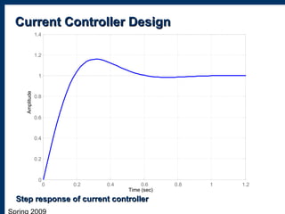
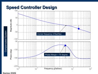
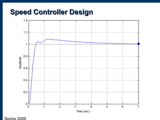
2) Designing a current controller and speed controller in the frequency domain and simulating their performance.
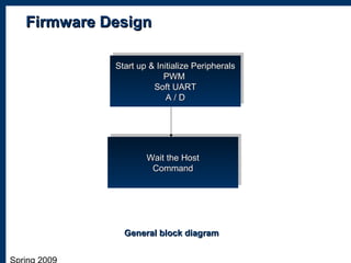
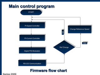
3) The physical implementation of the hardware including a general block diagram and descriptions of the hardware design, firmware design, and software design.
4) An overall design of the system operation and a graph showing the motor speed tracking the set point speed over time.


![Share 'speed control_of_dc_motor_using_microcontroller.pptx'[1][1]](https://cdn.slidesharecdn.com/ss_thumbnails/sharespeedcontrolofdcmotorusingmicrocontroller-181012151950-thumbnail.jpg?width=640&height=640&fit=bounds)