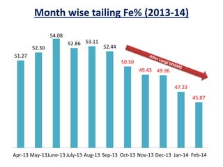
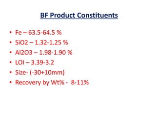
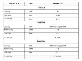
Beneficiation Plant
Scrubbing
(Scrubber)
Comminution
(Crusher, Rod Mill & Ball Mill)
Gravity Separation
(Coarse & Fines Jig)
Magnetic Separation
(MIMS, Coarse & Fines WHIMS)
Magnetic Separation
(MIMS, Coarse & Fines WHIMS)
Classification
(Screw Classifier, Hydrocyclone)
Dewatering
(Thickeners, Vaccum Belt Filter & Press Filter)
Methods Of Beneficiation Process
Beneficiation Plant Process Flow
Sheet
SBR
DD S
SD S
S CLR
C J
L O S
CRS
SD S
RM
BM
IT
CT
B F
CW
FW
- 30
- 30 + 5
- 5 + 1
- 1
- 0.15 - 1 + 0.15
- 0.15
- 0.15
- 30 + 10
- 10 + 5
- 5 + 1
- 1 + 0.5
- 0.5 +0.15 - 0.15
- 0.5
- 10
- 0.15
B F Product
Pellet Fines
Product
Tailing Pond
- 1
- 1
- 1
- 5 + 1
+ 5
+ 1
+ 0.15
Modified Beneficiation Plant
Process Flow Sheet With Longi
WHIMS
SBR
DD S
SD S
S CLR
C J
L O S
CRS
SD S
RM
BM
IT
CT
PF
B F
CW
FW LW 1
- 30
- 30 + 5
- 5 + 1
- 1
- 0.15 - 1 + 0.15
- 0.15
- 0.15
- 30 + 10
- 10 + 5
- 5 + 1
- 1 + 0.5
- 0.5 +0.15 - 0.15
- 0.5
- 10
- 0.15
B F Product
Pellet Fines
Product
Tailing
+ 30
+ 5
+ 0.15
- 1
- 5 + 1
Month wise quality report (2013-14)
58.99
59.54
60.50
59.62
60.17 60.34
59.77
60.65
59.97 59.91
59.48
64.20 63.99
64.43
62.98
63.33
64.43
63.55
64.07 63.96 63.77 63.94
62.22 62.33
62.93
61.94
62.34 62.42 62.40
63.24
62.38
62.72 62.79
51.27
52.30
54.08
52.86 53.11
52.44
50.50
49.43 49.36
47.23
45.87
Apr-13 May-13 June-13 July-13 Aug-13 Sep-13 Oct-13 Nov-13 Dec-13 Jan-14 Feb-14
Feed BF Fines Tails
Month wise tailing Fe% (2013-14)
51.27
52.30
54.08
52.86 53.11
52.44
50.50
49.43 49.36
47.23
45.87
Apr-13 May-13June-13 July-13 Aug-13 Sep-13 Oct-13 Nov-13 Dec-13 Jan-14 Feb-14
Feed Constituents
• Fe – 58.5-60.0 %
• SiO2 – 3.5 – 3.0 %
• Al2O3 – 5.5 – 5.5 %
• LOI – 6.5– 4.5 %
• Size – (-30mm)
BF Product Constituents
• Fe – 63.5-64.5 %
• SiO2 – 1.32-1.25 %
• Al2O3 – 1.98-1.90 %
• LOI – 3.39-3.2
• Size- (-30+10mm)
• Recovery by Wt% - 8-11%
Pellet Fines Product Constituents
• Fe – 62.5-63.5 %
• SiO2 – 1.76-1.65 %
• Al2O3 – 2.66-2.50 %
• LOI – 4.22-4.0 %
• Size- (-10mm to 0 mm )
• Recovery by Wt% – 62-64%
Tailing Constituents
• Fe – 46-48.5 %
• SiO2 – 12.0-10.20 %
• Al2O3 – 11.5-10.5 %
• LOI – 8.5-8.0 %
• Size- (-150 micron to 0 micron)
• By wt% - 30-25 %
Mass Balance
Average Mass Balance of plant
Sl. No Equipment Avg TPH Avg Wt %
1 Main Feed 716 100
2 Coarse jig feed 248 35
3 Coarse Jig Prod 174 24
4 Coarse jig reject 74 10
5 Fines Jig Feed 239 33
6 Fines Jig Prod 143 20
7 Fine Jig Reject 96 13
8 Classfier o/flow 72 10
9 Coarse Whims Feed 157 22.0
10 From R/mill 96 13
11 From Crusher 74 10
12 Total Coarse whims feed 327 46
13 Coarse whims product 98 14
14 Coarse whims Tails 229 32
15 Intermediate thickener o/flow 80 11
16 Intermediate thickener feed 301 42
17 Fines whims feed 221 31
18 Fines whims recovery 77 11
19 Fines whims tails 144 20
20 Longi whims feed 144 20
21 Longi whims product 43 6
22 Longi whims tailing 100 14
23 Total Tailings 180 25
Plant Major Modifications
• Installation of 2 No’s Additional Longi
whims
• Scope-To reduce the Fe in tailing to 43% and
• Increase the plant Recovery to 85%
• To reduce the ultra-fines(-
10micron) in Ball mill by
Maintaining
• Constant and consistent feed density
to Hydrocyclone through the Buffer
tank.
Buffer Tank
Plant Major Modifications
• Medium Intensity Magnetic
Separator (MIMS)
• Improve the recovery of fine
whims from 35% to 40% ,as
well as to avoid layer
formation of Ferro-Magnetic
Material in the Fine whims
Matrix.
MIMS
Plant Major Modifications
Modified Beneficiation Plant
Process Flow Sheet With Longi
WHIMS Phase 2
SBR
DD S
SD S
S CLR
C J
L O S
CRS
SD S
RM
BM
IT
CT
TT
PF
B F
CW
MMS
FW LW 1 LW 2
LW 2
- 30
- 30 + 5
- 5 + 1
- 1
- 0.15 - 1 + 0.15
- 0.15
- 0.15
- 30 + 10
- 10 + 5
- 5 + 1
- 1 + 0.5
- 0.5 +0.15 - 0.15
- 0.5 - 10
- 0.15
B F Product
Pellet Fines
Product
Tailing
+ 5
+ 1
- 1
- 5 + 1
+ 0.15
Recovery & Tailing Comparison
Sl.NO Details
Plant Tailing
(Fe in %)
Product (Recovery)
(%)
Tailing
(%)
1 Before Longi WHIMS 53.58 67.66 32.34
3 After Longi WHIMS 48.50 75 25
4
After Longi Phase 2 & MIMS
with Buffer tank
43.00 85 15
21
DESCRIPTION UNIT PARAMETER
WHIMS
Capacity M3 200T/H
Diameter of rotor MM 3600
Magnetic Induction Gauss Max 12000
Water Cunsumption M3 300M3/H
Quantity Nos 4
COARSE JIGS
Capacity TPH 125
Effective Jigging Area M2 6.6
Width of Air Chamber MM 800
Quantity No's 6
FINES JIGS
Capacity TPH 125
Effective Jigging Area
Quantity
M2
No’s
7.2
5
Equipment Details
22
DESCRIPTION UNIT PARAMETER
CRUSHER
Capacity TPH 200
Feed Size mm 5 - 30
Output size mm 1 - 5
ROD MILL
Capacity TPH 200TPH+Recycle load
Bulk Density T/M3 2.2
Feed Size mm 0 - 5
Output size < 1mm
BALL MILL
Capacity TPH 220TPH+Recycle load
Bulk Density T/M3 2.2
Feed Size mm 0 - 1
Output size < 0.1mm
23
DESCRIPTION UNIT PARAMETER
HYDRO CYCLONE
Capacity TPH 300TPH
Specific Gravity T/M3 3.5
Feed Size mm 0 - 1
VACUUM FILTER
Capacity TPH 200TPH
Specific Gravity T/M3 4
Feed Size mm 0 - 1
% weight solid in feed Approx. 60%
INTERMEDIATE THICKENER
Capacity TPH 450TPH
Feed Size mm 0 - 0.1
% weight solid in feed Approx. 9%
24
DESCRIPTION UNIT PARAMETER
CONCENTRATE THICKENER
Capacity TPH 200TPH
Specific Gravity 4
Feed Size mm 0 - 0.1
% weight solid in feed Approx. 18%
Quantity Nos 1
TAILLING THICKENER
Capacity TPH 300TPH
Specific Gravity 2.5
Feed Size mm 0 - 0.5
% weight solid in feed Approx. 6.9%
Quantity Nos 1
Thank You !!!

Presentation for IMMT

  • 1.
  • 2.
    Scrubbing (Scrubber) Comminution (Crusher, Rod Mill& Ball Mill) Gravity Separation (Coarse & Fines Jig) Magnetic Separation (MIMS, Coarse & Fines WHIMS) Magnetic Separation (MIMS, Coarse & Fines WHIMS) Classification (Screw Classifier, Hydrocyclone) Dewatering (Thickeners, Vaccum Belt Filter & Press Filter) Methods Of Beneficiation Process
  • 3.
  • 4.
    SBR DD S SD S SCLR C J L O S CRS SD S RM BM IT CT B F CW FW - 30 - 30 + 5 - 5 + 1 - 1 - 0.15 - 1 + 0.15 - 0.15 - 0.15 - 30 + 10 - 10 + 5 - 5 + 1 - 1 + 0.5 - 0.5 +0.15 - 0.15 - 0.5 - 10 - 0.15 B F Product Pellet Fines Product Tailing Pond - 1 - 1 - 1 - 5 + 1 + 5 + 1 + 0.15
  • 5.
    Modified Beneficiation Plant ProcessFlow Sheet With Longi WHIMS
  • 6.
    SBR DD S SD S SCLR C J L O S CRS SD S RM BM IT CT PF B F CW FW LW 1 - 30 - 30 + 5 - 5 + 1 - 1 - 0.15 - 1 + 0.15 - 0.15 - 0.15 - 30 + 10 - 10 + 5 - 5 + 1 - 1 + 0.5 - 0.5 +0.15 - 0.15 - 0.5 - 10 - 0.15 B F Product Pellet Fines Product Tailing + 30 + 5 + 0.15 - 1 - 5 + 1
  • 7.
    Month wise qualityreport (2013-14) 58.99 59.54 60.50 59.62 60.17 60.34 59.77 60.65 59.97 59.91 59.48 64.20 63.99 64.43 62.98 63.33 64.43 63.55 64.07 63.96 63.77 63.94 62.22 62.33 62.93 61.94 62.34 62.42 62.40 63.24 62.38 62.72 62.79 51.27 52.30 54.08 52.86 53.11 52.44 50.50 49.43 49.36 47.23 45.87 Apr-13 May-13 June-13 July-13 Aug-13 Sep-13 Oct-13 Nov-13 Dec-13 Jan-14 Feb-14 Feed BF Fines Tails
  • 8.
    Month wise tailingFe% (2013-14) 51.27 52.30 54.08 52.86 53.11 52.44 50.50 49.43 49.36 47.23 45.87 Apr-13 May-13June-13 July-13 Aug-13 Sep-13 Oct-13 Nov-13 Dec-13 Jan-14 Feb-14
  • 9.
    Feed Constituents • Fe– 58.5-60.0 % • SiO2 – 3.5 – 3.0 % • Al2O3 – 5.5 – 5.5 % • LOI – 6.5– 4.5 % • Size – (-30mm)
  • 10.
    BF Product Constituents •Fe – 63.5-64.5 % • SiO2 – 1.32-1.25 % • Al2O3 – 1.98-1.90 % • LOI – 3.39-3.2 • Size- (-30+10mm) • Recovery by Wt% - 8-11%
  • 11.
    Pellet Fines ProductConstituents • Fe – 62.5-63.5 % • SiO2 – 1.76-1.65 % • Al2O3 – 2.66-2.50 % • LOI – 4.22-4.0 % • Size- (-10mm to 0 mm ) • Recovery by Wt% – 62-64%
  • 12.
    Tailing Constituents • Fe– 46-48.5 % • SiO2 – 12.0-10.20 % • Al2O3 – 11.5-10.5 % • LOI – 8.5-8.0 % • Size- (-150 micron to 0 micron) • By wt% - 30-25 %
  • 13.
  • 14.
    Average Mass Balanceof plant Sl. No Equipment Avg TPH Avg Wt % 1 Main Feed 716 100 2 Coarse jig feed 248 35 3 Coarse Jig Prod 174 24 4 Coarse jig reject 74 10 5 Fines Jig Feed 239 33 6 Fines Jig Prod 143 20 7 Fine Jig Reject 96 13 8 Classfier o/flow 72 10 9 Coarse Whims Feed 157 22.0 10 From R/mill 96 13 11 From Crusher 74 10 12 Total Coarse whims feed 327 46 13 Coarse whims product 98 14 14 Coarse whims Tails 229 32 15 Intermediate thickener o/flow 80 11 16 Intermediate thickener feed 301 42 17 Fines whims feed 221 31 18 Fines whims recovery 77 11 19 Fines whims tails 144 20 20 Longi whims feed 144 20 21 Longi whims product 43 6 22 Longi whims tailing 100 14 23 Total Tailings 180 25
  • 15.
    Plant Major Modifications •Installation of 2 No’s Additional Longi whims • Scope-To reduce the Fe in tailing to 43% and • Increase the plant Recovery to 85%
  • 16.
    • To reducethe ultra-fines(- 10micron) in Ball mill by Maintaining • Constant and consistent feed density to Hydrocyclone through the Buffer tank. Buffer Tank Plant Major Modifications
  • 17.
    • Medium IntensityMagnetic Separator (MIMS) • Improve the recovery of fine whims from 35% to 40% ,as well as to avoid layer formation of Ferro-Magnetic Material in the Fine whims Matrix. MIMS Plant Major Modifications
  • 18.
    Modified Beneficiation Plant ProcessFlow Sheet With Longi WHIMS Phase 2
  • 19.
    SBR DD S SD S SCLR C J L O S CRS SD S RM BM IT CT TT PF B F CW MMS FW LW 1 LW 2 LW 2 - 30 - 30 + 5 - 5 + 1 - 1 - 0.15 - 1 + 0.15 - 0.15 - 0.15 - 30 + 10 - 10 + 5 - 5 + 1 - 1 + 0.5 - 0.5 +0.15 - 0.15 - 0.5 - 10 - 0.15 B F Product Pellet Fines Product Tailing + 5 + 1 - 1 - 5 + 1 + 0.15
  • 20.
    Recovery & TailingComparison Sl.NO Details Plant Tailing (Fe in %) Product (Recovery) (%) Tailing (%) 1 Before Longi WHIMS 53.58 67.66 32.34 3 After Longi WHIMS 48.50 75 25 4 After Longi Phase 2 & MIMS with Buffer tank 43.00 85 15
  • 21.
    21 DESCRIPTION UNIT PARAMETER WHIMS CapacityM3 200T/H Diameter of rotor MM 3600 Magnetic Induction Gauss Max 12000 Water Cunsumption M3 300M3/H Quantity Nos 4 COARSE JIGS Capacity TPH 125 Effective Jigging Area M2 6.6 Width of Air Chamber MM 800 Quantity No's 6 FINES JIGS Capacity TPH 125 Effective Jigging Area Quantity M2 No’s 7.2 5 Equipment Details
  • 22.
    22 DESCRIPTION UNIT PARAMETER CRUSHER CapacityTPH 200 Feed Size mm 5 - 30 Output size mm 1 - 5 ROD MILL Capacity TPH 200TPH+Recycle load Bulk Density T/M3 2.2 Feed Size mm 0 - 5 Output size < 1mm BALL MILL Capacity TPH 220TPH+Recycle load Bulk Density T/M3 2.2 Feed Size mm 0 - 1 Output size < 0.1mm
  • 23.
    23 DESCRIPTION UNIT PARAMETER HYDROCYCLONE Capacity TPH 300TPH Specific Gravity T/M3 3.5 Feed Size mm 0 - 1 VACUUM FILTER Capacity TPH 200TPH Specific Gravity T/M3 4 Feed Size mm 0 - 1 % weight solid in feed Approx. 60% INTERMEDIATE THICKENER Capacity TPH 450TPH Feed Size mm 0 - 0.1 % weight solid in feed Approx. 9%
  • 24.
    24 DESCRIPTION UNIT PARAMETER CONCENTRATETHICKENER Capacity TPH 200TPH Specific Gravity 4 Feed Size mm 0 - 0.1 % weight solid in feed Approx. 18% Quantity Nos 1 TAILLING THICKENER Capacity TPH 300TPH Specific Gravity 2.5 Feed Size mm 0 - 0.5 % weight solid in feed Approx. 6.9% Quantity Nos 1
  • 25.