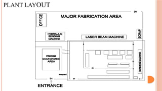
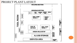
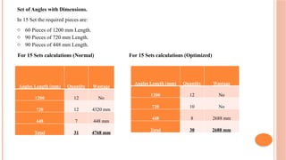
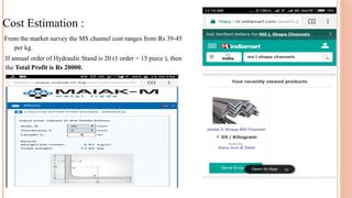
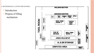
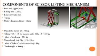
THEEM COLLEGE OF ENGINEERING
PROJECT ON
Implementation of 5S & Improvement Methodology
At Fledon Engineering Works
Partial Fulfilment of Dissertation work by-
Khan Mushran
Khawaja Moinuddin
Shaikh Salman
Shaikh Taurait
UNDER THE GUIDANCE OF : PROF. UMAR JAMADAR
INTRODUCTION OF COMPANY
Fledon Engineering Works
AN ISO 9001:2008 COMPANY
 Mfg. of Automotive Component , Sheet Metal Fabrication , Composite Panels &
Precision Machining
 Year of Establishment :- 2000
 Major Vendors : Mahindra & Mahindra
PLANT LAYOUT
PROJECT PLANT LAYOUT
PROBLEM STATEMENT
 Improper utilization of workspace area.
 Back Flow of material.
 Poor placement of machining equipment.
 Problems in material handling causing unnecessary increase in production time and cost.
 Reduce the work load on workers by adopting new techniques
PROBLEM STATE SCENARIO
REVIEW OF LITERATURE
Sr.No Paper Name Year Author Purpose
1 Efficiency Improvement of a Plant 2014
Vivekanand s Gogi, Rohith Shashi Kiran , Suhail
M Shaikh
To study and improve the current plant layout and are
analysed & designed by using
diagram.
2
Production Optimization for Industries
2014
Yosra Ojaghia, Alireza Khademia, Noordin Mohd
Yusof
To reduce the costs of their product.
3
Improvement in Plant Layout Using Material Handling
2012 Amrita Kirtane, Nagendra Sohani
Produce complete coupling by using the same
Mfg. facilities without major changes.
4 Implementation Of 5S Methodology In Industries 2011 R. S. Agrahari, P.A. Dangle, Implementation of 5S methodology in industry
K.V.Chandratre And improvements before and after 5S pictures
5 DESIGN AND ANALYSIS OF 2011 JAYDEEP M. BHATT The design described in the paper is to developed
AN AERIAL SCISSOR LIFT MILAN J. PANDYA lift mechanism
operated by mechanical means so that the
AIMS & OBJECTIVES
 Reduce manufacturing cycle time. (Fixtures)
 Reduce delays and damage. (5S)
 Promote safety and improve working conditions. (5S) (lifting mechanism)
 Increase/Improve productivity and reduce cost . (material optimization)
 Material flow should be in a streamline. And move as short distance as possible. (lifting
mechanism)
1. METHODOLOGY (5S)
PROPOSED IMPLEMENTATION OF 5S IN PROJECT AREA
(RACK ASSEMBLY) :
Present Scenario Proposed Table
PROPOSE IMPLEMENTATION OF 5S IN PROJECT AREA :
BEFORE AFTER
(WELDING)
Present Scenario
Proposed Table
BEFORE AFTER
PROPOSE IMPLEMENTATION OF 5S IN PROJECT AREA (BUFFING)
Present scenario Proposed table
2. METHODOLOGY ( FIXTURES )
Step Operation
Time
(minutes)
1 Chalk Marking 2
2
Marking With Vernier
Caliper 10
3 Center Punch 4
Total 16
Total existing time for 1 set is 16 minutes
Total existing time for 5 set is 1 hrs 20 minutes
1. Drilling Operation on top surface demanding 14 holes.
2. Drilling Operation on side surface demanding 8 holes.
Focused View of 14 Drilling Holes
Existing strategy/procedure for drilling 14 holes.
Proposed Strategy/procedure for drilling 14 holes.
Step Operation
Time
(minutes)
1 Clamping of gauge 0.5
2 Marking of holes with gauge 3
3 Unclamping of gauge 0.5
Total 4
Total proposed time for 1 set is 4 minutes
Total proposed time for 5 set is 20 minutes
BEFORE AFTER
Focused View of 08 Drilling Holes
Existing strategy/procedure for drilling 8 holes. Proposed strategy/procedure for drilling 8 holes.
Step Operation
Time
(minutes)
1 Chalk Marking 1
2
Marking With Vernier
Caliper 5
3 Center Punch 2
Total 8
Step Operation
Time
(minutes)
1 Clamping of gauge on one side 0.5
2
Marking of holes with gauge on
one side 1
3 Unclamping of gauge 0.5
4 Clamping of gauge on other side 0.5
5
Marking of holes with gauge on
another side 1
6 Unclamping of gauge 0.5
Total 4
Total proposed time for 1 set is 4 minutes
Total proposed time for 5 set is 20 minutes
Total existing time for 1 set is 8 minutes
Total existing time for 5 set is 40 minutes
3.METHODOLOGY (MATERIAL OPTIMIZATION)
 For making of Hydraulic Stand MS material angles (L-type ) are used. Angles are cut in
proper dimension according to their size.
 As per the demand of Hydraulic Stand the size of the Angle is 6 meter which is available.
 The details of the angles are given as below:
Angles
Quantit
y Dimensional Length (mm)
A 1 720
B 1 720
C 6 448
D 4 720
E 4 1200
Set of Angles with Dimensions.
In 15 Set the required pieces are:
o 60 Pieces of 1200 mm Length.
o 90 Pieces of 720 mm Length.
o 90 Pieces of 448 mm Length.
For 15 Sets calculations (Normal) For 15 Sets calculations (Optimized)
Angles Length (mm) Quantity Wastage
1200 12 No
720 12 4320 mm
448 7 448 mm
Total 31 4768 mm
Angles Length (mm) Quantity Wastage
1200 12 No
720 10 No
448 8 2688 mm
Total 30 2688 mm
Cost Estimation :
From the market survey the MS channel cost ranges from Rs 39-45
per kg.
If annual order of Hydraulic Stand is 20 (1 order = 15 piece ), then
the Total Profit is Rs 20000.
4. METHODOLOGY ( LIFTING MECHANISM )
 Introduction
 Propose of lifting
mechanism
COMPONENTS OF SCISSOR LIFTING MECHANISM
 Base and Upper plate
 Lifting Arm (Links)
 Lead screw and nut
 Tie rod
 Motor , Bearing , Gears , Chain
 Mass to be put on lift : 300kg
 Taking FOS = 1.5 for mass in pallet 300x 1.5 = 450 kg
 Mass of top frame= 22.5 kg
 Mass of each link: 5kg (5*4)=20kg
 Mass of links of cylinder mounting= 4kg
 Total weight = 500kg
MAIN COMPONENTS OF SCISSOR LIFTING MECHANISM
 Base plate And Upper plate
The upper plate in a scissor lift is used to place the load and transfer it to the links. The designing
of the upper plate is undertaken similar as the base plate
Base Plate (1000*6000*100) Upper Plate
 Design Of Links
Links are made of MS material (500mm) which are connected with
tie rod .
Maximum lift = 8 feet ( 3 to 4 links )
Minimum lift = 0.1 feet (angle 8)
 Lead Screw and Nut
 In lifting mechanism square thread power screw is used
with screw nut
 Torque to be lifted
 Efficiency of screw
COST ESTIMATION
Sr.No Name of Material Qty Material Cost Of Material Manufacturing Operation
1
Scissor lifting Arms
(links) 12 MS 3000 Laser cutting and drilling
2 Lifting Platform 2 MS 1200
Laser cutting and hand
press
3 Lead Screw 1 SS 10000 From Market
4 Tie Rod 3 MS 1000
Turning and Facing
operation
5 Motor (if necessary) 1 10000 From Market
6 Bearing 2 SS 3000 From Market
Total=18200
 Advantages
 Reduce material handling time
 Economic and Technical feasibility
 Lift high load at less effort
 Mechanism provide self locking system
 By using scissor lift one can avoid different injuries
 Damage to they product while handling is eliminated
 Scissor lifts does not require any large containment places ,it can be stored in minimum area
 Disadvantage
 Height of the elevation is limited
 Periodically lubrication is to be done for smooth working
 Using chain drive for power transmission lead to the problem of noise
 Investment cost is high
Conclusion :
The Project focuses on IMPLEMENTATION OF TECHNIQUES in order to increase
productivity and streamline flow of material.
And also the storage space plays an important role in saving space and reduce the
chances of accidents.
THANK YOU

PPT PHASE 3 project detail by engineering student

  • 1.
    THEEM COLLEGE OFENGINEERING PROJECT ON Implementation of 5S & Improvement Methodology At Fledon Engineering Works Partial Fulfilment of Dissertation work by- Khan Mushran Khawaja Moinuddin Shaikh Salman Shaikh Taurait UNDER THE GUIDANCE OF : PROF. UMAR JAMADAR
  • 2.
    INTRODUCTION OF COMPANY FledonEngineering Works AN ISO 9001:2008 COMPANY  Mfg. of Automotive Component , Sheet Metal Fabrication , Composite Panels & Precision Machining  Year of Establishment :- 2000  Major Vendors : Mahindra & Mahindra
  • 3.
  • 4.
  • 5.
    PROBLEM STATEMENT  Improperutilization of workspace area.  Back Flow of material.  Poor placement of machining equipment.  Problems in material handling causing unnecessary increase in production time and cost.  Reduce the work load on workers by adopting new techniques
  • 6.
  • 7.
  • 8.
    REVIEW OF LITERATURE Sr.NoPaper Name Year Author Purpose 1 Efficiency Improvement of a Plant 2014 Vivekanand s Gogi, Rohith Shashi Kiran , Suhail M Shaikh To study and improve the current plant layout and are analysed & designed by using diagram. 2 Production Optimization for Industries 2014 Yosra Ojaghia, Alireza Khademia, Noordin Mohd Yusof To reduce the costs of their product. 3 Improvement in Plant Layout Using Material Handling 2012 Amrita Kirtane, Nagendra Sohani Produce complete coupling by using the same Mfg. facilities without major changes. 4 Implementation Of 5S Methodology In Industries 2011 R. S. Agrahari, P.A. Dangle, Implementation of 5S methodology in industry K.V.Chandratre And improvements before and after 5S pictures 5 DESIGN AND ANALYSIS OF 2011 JAYDEEP M. BHATT The design described in the paper is to developed AN AERIAL SCISSOR LIFT MILAN J. PANDYA lift mechanism operated by mechanical means so that the
  • 9.
    AIMS & OBJECTIVES Reduce manufacturing cycle time. (Fixtures)  Reduce delays and damage. (5S)  Promote safety and improve working conditions. (5S) (lifting mechanism)  Increase/Improve productivity and reduce cost . (material optimization)  Material flow should be in a streamline. And move as short distance as possible. (lifting mechanism)
  • 10.
  • 11.
    PROPOSED IMPLEMENTATION OF5S IN PROJECT AREA (RACK ASSEMBLY) : Present Scenario Proposed Table
  • 12.
    PROPOSE IMPLEMENTATION OF5S IN PROJECT AREA : BEFORE AFTER
  • 13.
  • 14.
  • 15.
    PROPOSE IMPLEMENTATION OF5S IN PROJECT AREA (BUFFING) Present scenario Proposed table
  • 16.
    2. METHODOLOGY (FIXTURES ) Step Operation Time (minutes) 1 Chalk Marking 2 2 Marking With Vernier Caliper 10 3 Center Punch 4 Total 16 Total existing time for 1 set is 16 minutes Total existing time for 5 set is 1 hrs 20 minutes 1. Drilling Operation on top surface demanding 14 holes. 2. Drilling Operation on side surface demanding 8 holes. Focused View of 14 Drilling Holes Existing strategy/procedure for drilling 14 holes.
  • 17.
    Proposed Strategy/procedure fordrilling 14 holes. Step Operation Time (minutes) 1 Clamping of gauge 0.5 2 Marking of holes with gauge 3 3 Unclamping of gauge 0.5 Total 4 Total proposed time for 1 set is 4 minutes Total proposed time for 5 set is 20 minutes BEFORE AFTER
  • 18.
    Focused View of08 Drilling Holes
  • 19.
    Existing strategy/procedure fordrilling 8 holes. Proposed strategy/procedure for drilling 8 holes. Step Operation Time (minutes) 1 Chalk Marking 1 2 Marking With Vernier Caliper 5 3 Center Punch 2 Total 8 Step Operation Time (minutes) 1 Clamping of gauge on one side 0.5 2 Marking of holes with gauge on one side 1 3 Unclamping of gauge 0.5 4 Clamping of gauge on other side 0.5 5 Marking of holes with gauge on another side 1 6 Unclamping of gauge 0.5 Total 4 Total proposed time for 1 set is 4 minutes Total proposed time for 5 set is 20 minutes Total existing time for 1 set is 8 minutes Total existing time for 5 set is 40 minutes
  • 20.
    3.METHODOLOGY (MATERIAL OPTIMIZATION) For making of Hydraulic Stand MS material angles (L-type ) are used. Angles are cut in proper dimension according to their size.  As per the demand of Hydraulic Stand the size of the Angle is 6 meter which is available.  The details of the angles are given as below: Angles Quantit y Dimensional Length (mm) A 1 720 B 1 720 C 6 448 D 4 720 E 4 1200
  • 21.
    Set of Angleswith Dimensions. In 15 Set the required pieces are: o 60 Pieces of 1200 mm Length. o 90 Pieces of 720 mm Length. o 90 Pieces of 448 mm Length. For 15 Sets calculations (Normal) For 15 Sets calculations (Optimized) Angles Length (mm) Quantity Wastage 1200 12 No 720 12 4320 mm 448 7 448 mm Total 31 4768 mm Angles Length (mm) Quantity Wastage 1200 12 No 720 10 No 448 8 2688 mm Total 30 2688 mm
  • 22.
    Cost Estimation : Fromthe market survey the MS channel cost ranges from Rs 39-45 per kg. If annual order of Hydraulic Stand is 20 (1 order = 15 piece ), then the Total Profit is Rs 20000.
  • 23.
    4. METHODOLOGY (LIFTING MECHANISM )  Introduction  Propose of lifting mechanism
  • 24.
    COMPONENTS OF SCISSORLIFTING MECHANISM  Base and Upper plate  Lifting Arm (Links)  Lead screw and nut  Tie rod  Motor , Bearing , Gears , Chain  Mass to be put on lift : 300kg  Taking FOS = 1.5 for mass in pallet 300x 1.5 = 450 kg  Mass of top frame= 22.5 kg  Mass of each link: 5kg (5*4)=20kg  Mass of links of cylinder mounting= 4kg  Total weight = 500kg
  • 25.
    MAIN COMPONENTS OFSCISSOR LIFTING MECHANISM  Base plate And Upper plate The upper plate in a scissor lift is used to place the load and transfer it to the links. The designing of the upper plate is undertaken similar as the base plate Base Plate (1000*6000*100) Upper Plate
  • 26.
     Design OfLinks Links are made of MS material (500mm) which are connected with tie rod . Maximum lift = 8 feet ( 3 to 4 links ) Minimum lift = 0.1 feet (angle 8)
  • 27.
     Lead Screwand Nut  In lifting mechanism square thread power screw is used with screw nut  Torque to be lifted  Efficiency of screw
  • 28.
    COST ESTIMATION Sr.No Nameof Material Qty Material Cost Of Material Manufacturing Operation 1 Scissor lifting Arms (links) 12 MS 3000 Laser cutting and drilling 2 Lifting Platform 2 MS 1200 Laser cutting and hand press 3 Lead Screw 1 SS 10000 From Market 4 Tie Rod 3 MS 1000 Turning and Facing operation 5 Motor (if necessary) 1 10000 From Market 6 Bearing 2 SS 3000 From Market Total=18200
  • 29.
     Advantages  Reducematerial handling time  Economic and Technical feasibility  Lift high load at less effort  Mechanism provide self locking system  By using scissor lift one can avoid different injuries  Damage to they product while handling is eliminated  Scissor lifts does not require any large containment places ,it can be stored in minimum area  Disadvantage  Height of the elevation is limited  Periodically lubrication is to be done for smooth working  Using chain drive for power transmission lead to the problem of noise  Investment cost is high
  • 30.
    Conclusion : The Projectfocuses on IMPLEMENTATION OF TECHNIQUES in order to increase productivity and streamline flow of material. And also the storage space plays an important role in saving space and reduce the chances of accidents.
  • 31.