You're correct. The mass/surface area ratio is higher for the larger 3 mm raindrop compared to the 1 mm raindrop. Good work verifying the statement from the text.
Head of IntellectualProperty, The Open University
Contents
Introduction 5
Learning Outcomes 6
1 Some facts about water 7
2 The hydrological cycle 7
2.1 Introduction 7
2.2 Evaporation 8
2.3 Transpiration 9
2.4 Condensation 9
2.5 Air circulation 9
2.6 Precipitation 9
2.7 Infiltration 13
2.8 Surface run-off 13
2.9 Percolation 15
2.10 Aquifers 15
2.11 Storage 16
2.12 Summary 18
3 The natural aquatic environment 20
3.1 Water, the medium of life 20
3.2 Dissolved oxygen 22
3.3 Physical characteristics of natural waters 29
3.4 Chemical characteristics of natural waters 31
3.5 Biological characteristics of natural waters 35
4.6 Tidal rivers and estuaries 45
4.7 Summary 47
5 Water treatment 50
5.1 Introduction 50
5.2 Preliminary treatment 52
5.3 Coagulation and flocculation 54
5.4 Sedimentation 56
5.5 Flotation 64
5.6 Filtration 65
5.7 Disinfection 67
5.8 Additional treatment 72
5.9 Membrane filtration 75
5.10 Fluoridation 77
5.11 Plumbo-solvency 80
5.12 Sludge treatment and disposal 81
5.13 Groundwater treatment 81
5.14 Desalination 81
5.15 Summary 85
3 of 100 http://www.open.edu/openlearn/science-maths-technology/engineering-and-technology/technology/potable-
water-treatment/content-section-0?utm_source=openlearnutm_campaign=olutm_medium=ebook
Wednesday 21 November 2018
4.
6 Water supply85
6.1 Introduction 85
6.2 Service reservoirs 88
6.3 Distribution systems 94
6.4 Summary 96
Conclusion 98
Keep on learning 98
References 99
Acknowledgements 99
4 of 100 http://www.open.edu/openlearn/science-maths-technology/engineering-and-technology/technology/potable-
water-treatment/content-section-0?utm_source=openlearnutm_campaign=olutm_medium=ebook
Wednesday 21 November 2018
5.
Introduction
This course isfrom our archive and it is an adapted extract from Environmental Control
and Public Health (T210) which is no longer in presentation. If you wish to study formally
at The Open University, you may wish to explore the courses we offer in this
curriculum area.
Without it we are dead! Water is essential, but what processes must it go
through to become fit for human consumption? This course will guide you
through the continuous cycling of water between land, open water surfaces and
the sea before moving on to an overview of the water treatment and supply
process.
This OpenLearn course provides a sample of level 1 study in Technology
Introduction
5 of 100 http://www.open.edu/openlearn/science-maths-technology/engineering-and-technology/technology/potable-
water-treatment/content-section-0?utm_source=openlearnutm_campaign=olutm_medium=ebook
Wednesday 21 November 2018
6.
Learning Outcomes
After studyingthis course, you should be able to:
l describe the operation and mechanisms of the hydrological cycle
l list and describe the major physical, chemical and biological characteristics of clean fresh water, and explain their
effects on aquatic organisms
l explain the mode by which potable water is produced through the processes of screening, microstraining,
aeration, coagulation and flocculation, sedimentation, flotation, filtration and disinfection
l explain how the issues of nitrates, trace organics, fluoridation and plumbo-solvency can be dealt with in potable
water supply
l describe the main desalination processes used to produce potable water from saline or brackish sources.
7.
1 Some factsabout water
Did you know?
At any one time, half the hospital beds in the world are said to be occupied by people
suffering from water-borne illnesses.
This Unit looks at water treatment and gives an insight into the use of science and
maths for the betterment of people's lives.
Video content is not available in this format.
We can all relate to water. We know we need it to survive – indeed all the great
civilizations of the world (the Egyptian, Greek, Mesopotamian, etc.) were centred around
river valleys where there was a plentiful supply of fresh, clean water.
When we take water into our bodies, it is used in several ways – as a coolant (keeping our
body at a temperature of 98.4°F or 36.9°C), as a waste disposal medium, as a conductor
for nerve impulses, and as a component in the digestion of food.
You can see from the above that even if you didn't move an inch, your body would still
need water to keep you alive. A survival handbook I read recently says that people can
live for 21 days without food but for only 10 days without water. I suspect this must be for a
temperate climate. In the desert, in summer, the limit might only be a day or two.
Water is a fascinating subject, encompassing chemistry, biology and physics. Apart from
keeping us all alive, water is used extensively in industrial processes, and for recreation
and transport. It is something we can't do without. The water we use for domestic
purposes has to be free of contaminants – more than 25000 people are said to die each
day from ingesting poor-quality water!
In this course, we start from the basics – the hydrological cycle and the natural aquatic
environment. Then we gently glide into water treatment, water supply and water
conservation. As a society, we are getting more and more water-hungry – one of the signs
of affluence!
2 The hydrological cycle
2.1 Introduction
The hydrological cycle, the continuous cycling of water between land, open water
surfaces and the sea, either directly or indirectly, is an extremely complex process which
has been known for a long time (Figure 1). The identifiable mechanisms of the cycle are
complicated not only by the characteristics of air-water-land interfaces across which the
cycle operates, but also by climatic factors which vary in both time and space. The various
operations and mechanisms within the cycle are illustrated in Figure 2 and are described
over the next few pages.
1 Some facts about water
7 of 100 http://www.open.edu/openlearn/science-maths-technology/engineering-and-technology/technology/potable-
water-treatment/content-section-0?utm_source=openlearnutm_campaign=olutm_medium=ebook
Wednesday 21 November 2018
8.
Figure 1 Probablythe oldest reference to the hydrological cycle, the Chandogya, one of
the principal Upanishads, says 'rivers … lead from sea to sea'. It reveals that as early as
1000 BCE, attempts were being made to interpret and explain recurrent phenomena on
the basis of direct experience. (Cartoon by Ajit Nunan)
Interactive content is not available in this format.
Figure 2 The hydrological cycle (volumes are in Tm3
= 1012
m3
)
2.2 Evaporation
At an interface with the atmosphere, water changes its state from a liquid to a vapour in
response to an increase in temperature caused by an external heat source. This
temperature change is normally the result of solar radiation. The transfer of moisture into
the air is called evaporation. The process is also controlled by the relative humidity, or
level of vapour saturation, of the air. The greater the relative humidity of the air, the less
likely it is that evaporation will take place for a given temperature. In addition to the direct
controls of temperature and humidity, the rate of evaporation is also influenced by wind
velocity, since continuous wind currents will carry away saturated air from the water
surface, allowing more water to evaporate from the surface.
Evaporation is variable with both time and place because the controlling factors
themselves provide transient conditions. It will occur almost continuously from stretches
of permanent open water and intermittently, but usually at a lower rate, from land
surfaces.
Over land surfaces, the rate of evaporation varies with the extent to which the ground is
saturated. If the soil saturation level (i.e. the level to which all the voids are filled with
water) is low, water moves up to the surface by the effect of capillary action. This controls
the rate at which water will evaporate. Evaporation takes place from a sandy soil
2 The hydrological cycle
8 of 100 http://www.open.edu/openlearn/science-maths-technology/engineering-and-technology/technology/potable-
water-treatment/content-section-0?utm_source=openlearnutm_campaign=olutm_medium=ebook
Wednesday 21 November 2018
9.
saturated up tothe surface as quickly as it will from a lake, but the evaporation rate from
saturated loam and clay soils is only 75–90% of that from an open body of water.
As it begins to rain, a large proportion of the water droplets is intercepted by the leaves of
trees and other vegetation before reaching the ground. By this process of interception,
water held on leaves and branches is returned rapidly to the atmosphere by evaporation.
In forested areas, as much as 40% of light rain may be intercepted by foliage, although
overall the fraction is probably nearer to 10–25%.
2.3 Transpiration
If there were no vegetation, the rate of evaporation from land surfaces after rain would
diminish rapidly to a very low value. Plants increase this rate by transpiration. In this
process, water is transferred from the soil through the roots to the leaves by osmosis and
capillary action. Water evaporates from the surface of the leaves and the resulting vapour
diffuses into the atmosphere. For hydrological measurements, this phenomenon is
frequently lumped with evaporation because the two processes are not truly
distinguishable using simple observational techniques over an area of mixed land use.
The complete process of removal of moisture to the atmosphere from land surfaces by
evaporation and transpiration is then termed evapotranspiration.
2.4 Condensation
As air rises it expands, owing to the decrease in pressure with height, and as it expands,
in theory it cools at an average rate of 1°C for every 100 m of altitude. As the air cools, it
becomes saturated with water vapour which condenses around small particles in the air.
These particles may occur naturally, such as soil particles or salt particles residual to
evaporation of sea spray, or they may be produced artificially during combustion. A
measure of the necessary cooling to produce condensation is the dewpoint, which is the
temperature at which air of a given absolute humidity and at a given pressure begins to
give up its water as drops of dew. When moist air is chilled to a temperature below its
dewpoint, in the presence of suitable minute particles, a cloud or mist will form.
2.5 Air circulation
At this stage, air circulation enters and plays a dual role. Firstly, winds transmit moisture
horizontally from one location to another. In this way, moisture derived from oceanic
evaporation can be transported many miles to a land mass. Secondly, convective or
vertical currents arising from unequal heating or cooling can transmit moisture upwards.
When it cools, some of the water vapour condenses. It is from these currents that most
precipitation develops.
2.6 Precipitation
Precipitation is defined as the depth of rainfall, or the water equivalent of snow, sleet and
hail falling during a given measurement period. It may be in the form of rain, snow, sleet or
hail, or in minor forms such as dew and hoar frost, but existing theories do not yet
2 The hydrological cycle
9 of 100 http://www.open.edu/openlearn/science-maths-technology/engineering-and-technology/technology/potable-
water-treatment/content-section-0?utm_source=openlearnutm_campaign=olutm_medium=ebook
Wednesday 21 November 2018
10.
satisfactorily account forall the observed characteristics. In tropical climates, precipitation
occurs as a result of the gradual coalescence of the tiny condensed droplets as they
collide within the cloud layer. In cooler climates, the formation of ice crystals in the upper
levels of the cloud in turn is followed by crystal growth at the expense of water droplets,
and this results in snow or hail. When sufficient growth has occurred, the large water
drops or ice crystals have a larger ratio of mass to surface area than the small water drops
or ice crystals.
Self-assessment question
Verify the above statement that large drops have a larger mass surface area ratio than
small ones, by considering two rain drops of equivalent diameter 1 mm and 3 mm,
respectively. Take the density of the rainwater to be 998 kg m−3
.
Note: For a sphere of radius r, the
and the surface area = 4 π r2
.
2 The hydrological cycle
10 of 100 http://www.open.edu/openlearn/science-maths-technology/engineering-and-technology/technology/potable-
water-treatment/content-section-0?utm_source=openlearnutm_campaign=olutm_medium=ebook
Wednesday 21 November 2018
11.
Answer
Carrying out similarcalculations for the 3 mm raindrops, we get
2 The hydrological cycle
11 of 100 http://www.open.edu/openlearn/science-maths-technology/engineering-and-technology/technology/potable-
water-treatment/content-section-0?utm_source=openlearnutm_campaign=olutm_medium=ebook
Wednesday 21 November 2018
12.
Thus, the largedrop has a larger ratio of mass to surface area.
The increased mass to surface area ratio allows the large drops to fall more rapidly than
the small drops and they separate from the cloud. The small drops with very low velocity
remain in the air currents associated with the cloud.
The large-scale cooling needed to give significant amounts of precipitation is achieved by
lifting the air. There are three lifting processes (Figure 3) and these are used to describe
the type of precipitation. They are:
l frontal (or cyclonic) – resulting from warm moist air meeting;
l orographic – upward deflection of warm air streams by mountains;
l convective (or convectional) – uplift associated with local heating by solar radiation.
Lifting processes leading to precipitation:
Figure 3
Interactive content is not available in this format.
In the hydrological cycle, the total volume of water remains constant. The volume of water
precipitated must necessarily balance the volume evaporated (when considered over a
sufficiently long period of time to make variation in atmospheric storage of moisture
insignificant).
2 The hydrological cycle
12 of 100 http://www.open.edu/openlearn/science-maths-technology/engineering-and-technology/technology/potable-
water-treatment/content-section-0?utm_source=openlearnutm_campaign=olutm_medium=ebook
Wednesday 21 November 2018
13.
2.7 Infiltration
Entry ofprecipitation through the soil surface and on downwards, by gravity, is known as
infiltration. The rate at which this process can take place is governed by the permeability
(a measure of the ease with which water can flow through the subsurface layer) and by
the existing degree of saturation of the soil. Infiltration can be impeded by outcropping
impermeable rocks or by paved areas, and also by the presence of finegrained soils with a
low permeability (such as clay). At certain times it will be inhibited by frozen ground or
saturated soil, and in Arctic areas by frozen subsoil the whole year round.
The total amount of infiltration will depend upon the rate at which it can take place, and
upon the time available for water to seep into the ground. You should appreciate that rapid
run-off of water will reduce the time available for infiltration and decrease the total amount
taken into the ground.
2.8 Surface run-off
In some inland drainage areas, all water is removed by evaporation and infiltration.
However, precipitation not penetrating the land surface usually runs off the surface along
defined channels which have been produced by geological processes, previous storms,
or possibly by people. This accelerates the process. Its eventual destination is the ocean,
except, of course, where it runs to inland seas such as the Dead Sea. It is in the runoff
phase of the cycle that physical intervention by humans has been greatest. People have
(Figure 4):
l harnessed the potential energy of rivers to provide power;
l curbed erosion in order to protect dwellings and avoid the loss of fertile soil;
l impounded water for supply schemes;
l diverted flow for the irrigation of crops and to facilitate navigation; and
l drained land to improve its agricultural value.
2 The hydrological cycle
13 of 100 http://www.open.edu/openlearn/science-maths-technology/engineering-and-technology/technology/potable-
water-treatment/content-section-0?utm_source=openlearnutm_campaign=olutm_medium=ebook
Wednesday 21 November 2018
14.
Figure 4 Waterin our lives: (a) Itaipu Dam in Brazil
Figure 4 Water in our lives: (b) irrigation channels
2 The hydrological cycle
14 of 100 http://www.open.edu/openlearn/science-maths-technology/engineering-and-technology/technology/potable-
water-treatment/content-section-0?utm_source=openlearnutm_campaign=olutm_medium=ebook
Wednesday 21 November 2018
15.
2.9 Percolation
Movement ofinfiltrated water downwards through the zone of aeration (Figure 5) is known
as percolation. The infiltrated water which does not remain held by capillary forces in the
surface soils moves by the action of gravity through the unsaturated layers of soil or rock
until it arrives at the water table. Here the percolated water joins the body of groundwater
which seeps slowly to the sea.
Figure 5 Zones of subsurface water
2.10 Aquifers
Groundwater is water that, after infiltrating and percolating through surface soils, flows
into an aquifer, an underground water-bearing layer of porous rock. About one-third of the
UK's drinking water is drawn from aquifers.
To permit economic development, an aquifer must be able to transmit large quantities of
water from one point to another and therefore it must have a high permeability. The
groundwater contained in aquifers is released from springs and can be responsible for the
bulk of river flows.
2 The hydrological cycle
15 of 100 http://www.open.edu/openlearn/science-maths-technology/engineering-and-technology/technology/potable-
water-treatment/content-section-0?utm_source=openlearnutm_campaign=olutm_medium=ebook
Wednesday 21 November 2018
16.
Usually, aquifers arealluvial sands (sands which have been carried in suspension by
rivers or floods) and gravels, the coarser sedimentary rocks such as sandstone, and rocks
such as limestone in which chemical action has increased the water-bearing capacity. The
strata of relatively impermeable rocks that lie either above or below confined aquifers
(aquifers trapped between two impervious layers of rock) are called aquicludes.
The flow of groundwater takes place through the layer that is completely saturated. This
layer, not surprisingly, is called the zone of saturation (as shown in Figure 5).
2.11 Storage
In a given fixed space at any phase of the hydrological cycle, there is an inflow and an
outflow of water, the rates of which vary with time. The total cumulative difference
between inflow and outflow is the storage. So within that space there is a body of water
whose mass is not directly controlled by instantaneous values of inflow and outflow. For
example, in river flow the movement of the whole body of water in the channel is generally
downstream, yet a given reach contains a volume whose size may not change very much
over a period of settled, fairly dry weather. Also, water may be abstracted from this reach
at a greater rate than the inflow.
The storage element is most stable when it is large in relation to input and output
quantities. This implies that the stored volume of water is stable in large lakes and
reservoirs and also in aquifers, where the inflow and outflow rates are naturally low. As the
size of the system increases, so also does the stability.
In our discussion of the hydrological cycle we have presumed that the system is
completely stable, so both inflow and outflow are zero. This assumes that water present in
the hydrological cycle was formed at a very early stage in geological time. However, there
is a theory that suggests that water is continuing to form in the Earth's core. Water is
formed in small quantities, of course, by a number of artificial processes (e.g. in car
exhausts). We have also assumed that no water is lost to the system by escaping from the
Earth's gravitational pull.
The concept of storage is vital to the supply of water, since a major problem of supply
revolves around the provision of water at the right time. Water is, of course, in highest
demand in dry weather and we seek constantly to exploit or increase the existing storage
potential in the cycle.
The relative contributions to total storage are summarised in Figure 6 and Table 1. The
oceans of the world hold the bulk of the water on Earth. Thus the water resources of the
world are largely saline (salty).
2 The hydrological cycle
16 of 100 http://www.open.edu/openlearn/science-maths-technology/engineering-and-technology/technology/potable-
water-treatment/content-section-0?utm_source=openlearnutm_campaign=olutm_medium=ebook
Wednesday 21 November 2018
17.
Figure 6 Componentsof world water storage
Table 1 Total available water in the various storage components
of the hydrological cycle
Storage component Volume of water (1012
m3
) Volume (%, approx.)
Oceans 1 350 400 97.6
Ice caps and glaciers 26 000 1.9
Groundwater and soil moisture 7150 0.5
Freshwater lakes 125 0.009
Saline lakes 105 0.008
Rivers 1.7 0.0001
Atmosphere 13 0.001
From Table 1, it can be seen that only 2.4% of the Earth's water is non-saline, and that
much of this is locked up as ice.
Self-assessment question
Calculate the volume of surface fresh water available in the non-polar regions using
the figures in Table 1. What percentage of the total water available is this?
Answer
Surface freshwater available from:
2 The hydrological cycle
17 of 100 http://www.open.edu/openlearn/science-maths-technology/engineering-and-technology/technology/potable-
water-treatment/content-section-0?utm_source=openlearnutm_campaign=olutm_medium=ebook
Wednesday 21 November 2018
18.
As a percentageof the total water resource available (1 383 794.7×10¹²
m3
)
which is less than 0.01% – this is a very small amount indeed!
One thing which is not shown in Table 1, but which I'm sure you have thought about, is the
unevenness in the distribution of fresh water throughout the world. When I was working in
Kuwait we had a proposal from an organisation representing oil tanker owners. They
wanted to sell fresh water from Norway and Wales, brought as ballast in the tankers
coming to collect crude oil. For a variety of reasons, the proposals were rejected.
2.12 Summary
The hydrological cycle is a complex process involving evaporation, transpiration,
condensation, air circulation, precipitation, infiltration, surface run-off and percolation.
Aquifers are an important source of fresh water supplying about one-third of the UK's
potable water demand. Most of the world's water is present as saline water in the oceans.
Self-assessment question
What fraction of the total volume of water that circulates in the Earth's hydrological
cycle does river water represent?
2 The hydrological cycle
18 of 100 http://www.open.edu/openlearn/science-maths-technology/engineering-and-technology/technology/potable-
water-treatment/content-section-0?utm_source=openlearnutm_campaign=olutm_medium=ebook
Wednesday 21 November 2018
19.
Answer
i.e. 1.2 millionthsof the total available water.
Self-assessment question
What are the components of the hydrological cycle which can modify the volume of
groundwater resources?
Answer
The components are: rainfall, evapotranspiration, run-off, abstraction of surface water,
infiltration to groundwater storage, inflow and outflow of groundwater between the
aquifer and other areas or the sea, and the change in groundwater storage due to
abstraction.
Self-assessment question
Which of the following is the best description of evapotranspiration?
A The transfer of water from the oceans, seas and land surface to the air.
B The accelerated process of transfer of moisture to the air at a water-air interface
caused by an external heat source.
C The transfer of moisture from soil to the air through roots and leaves of plants.
D Items B and C together.
E The total removal of moisture to the atmosphere from land surfaces.
Answer
Option D is best, but option E is also valid.
Self-assessment question
How do the following affect infiltration?
(a) Dense vegetation.
(b) Steeply sloping land surface.
(c) Cultivated land.
(d) Roads and buildings.
2 The hydrological cycle
19 of 100 http://www.open.edu/openlearn/science-maths-technology/engineering-and-technology/technology/potable-
water-treatment/content-section-0?utm_source=openlearnutm_campaign=olutm_medium=ebook
Wednesday 21 November 2018
20.
Answer
(a) Dense vegetationreduces the rate of surface run-off and thus increases infiltration.
However, the effect will be offset to some extent by interception, whereby a large
proportion of the precipitation stays on the leaves of the vegetation and evaporates.
(b) Water runs rapidly off steeply sloping land surfaces so there is little time for
significant infiltration to occur.
(c) Cultivated land is in general subject to greater amounts of infiltration, unless the
land is sloping, when the effect will be as in (b).
(d) Tarmac, concrete and roofing surfaces are relatively impermeable, so that roads
and buildings promote run-off and reduce infiltration.
3 The natural aquatic environment
3.1 Water, the medium of life
The list of necessities for the provision of life includes various nutrients and water: water is
one of the basic resources needed for the process of photosynthesis. Since it is an
excellent solvent, water, even in its 'natural' state, is never pure H2O but contains a variety
of soluble inorganic and organic compounds. Water can also carry large amounts of
insoluble material in suspension. The amounts and types of impurities vary with location
and time of year, and determine some of the characteristics of a particular watercourse.
One of the most important determining factors is the presence of organic material in
solution or in suspension. Organic material can be used as 'food' by the organisms living
in natural water, provided the material is biodegradable. Biodegradable materials are
those organic substances which can be decomposed by micro-organisms (usually
bacteria and fungi) into inorganic substances. We have met the idea of food chains and
webs and the cycling of nutrients. The basis of a trophic system in a river is the content of
inorganic and organic materials in it, the biodegradation of these by decomposer
organisms, and the products of the photosynthetic activities of the primary producers.
In a water environment, as on land, the primary producers (green plants and algae) are
eaten by herbivores (primary consumers) and these in turn are devoured by the
secondary consumers (carnivores). The interdependence of these organisms gives a
complex food web within which there are many food chains, the successive links in the
chains being composed of different species in a predator-prey relationship.
For a river a typical food chain could be
Scavengers eat bottom debris, including dead organisms. If the latter are not eaten
immediately, the decomposers (bacteria and fungi) break them down, releasing nutrients
which can be taken up by plants.
Through this cyclic movement of nutrients, the water environment achieves an ecological
equilibrium. In a given stretch of water a balance occurs between total production of living
material and the occurrence of death and decomposition over a period of time. The river
3 The natural aquatic environment
20 of 100 http://www.open.edu/openlearn/science-maths-technology/engineering-and-technology/technology/potable-
water-treatment/content-section-0?utm_source=openlearnutm_campaign=olutm_medium=ebook
Wednesday 21 November 2018
21.
neither becomes chokedwith living organisms nor devoid of them – although, depending
on location and geological conditions, the numbers and varieties of the biota vary
enormously. The maintenance of equilibrium is dependent on the complexity of biota and
the interlinking of food chains and webs.
A typical river has several sources in high ground which are characterised by steep
gradients, swift current velocities, and erosion of the surrounding rocks and soil. As the
gradient lessens, the current velocity decreases and the river deepens and widens. The
river then tends to deposit stones, gravel and sand. This variation in the flow downhill has
a direct influence on the types of organisms and substratum to be found at different points
along the river. The whole length of the river can be subdivided into different zones, each
characterised by its own typical fauna and flora.
In contrast to rivers, standing bodies of water such as lakes and reservoirs may be
affected by thermal stratification. Figure 7 illustrates this effect for a typical lake. In the
summer, there is very little mixing between the cooler, denser water at the bottom of the
lake (hypolimnion) and the warmer, less dense water at the lake surface (epilimnion).
Thus, stream and river water running into the lake will tend to stay in the upper layer. This
water carries nutrients, so organisms flourish in the epilimnion and there is a high rate of
primary production. In the hypolimnion, the dead remains of primary production settle out,
forming a layer of bottom sediment. The lack of mixing between the layers (stratification)
together with the absence of light penetration to the bottom of the lake determine the
ecological characteristics of a deep lake or reservoir. In a deep lake, the absence of light
prevents the growth of plant life in the bottom layers, although decomposer and
scavenger micro-organisms can live on, and in, the bottom sediment.
Figure 7 Thermal stratification of a lake
In contrast to summer conditions, Figure 7 shows that in winter, thermal stratification is
absent. This is because the density of fresh water is greatest at 3.98°C (about 4°C). Thus,
when the temperature of the surface layer falls to this temperature, the layer will descend
to the bottom of the lake, displacing any colder (but less dense) water which will now rise
3 The natural aquatic environment
21 of 100 http://www.open.edu/openlearn/science-maths-technology/engineering-and-technology/technology/potable-
water-treatment/content-section-0?utm_source=openlearnutm_campaign=olutm_medium=ebook
Wednesday 21 November 2018
22.
to the surface.The lake 'turns over' and mixing occurs at all levels, leading to uniform
temperature and uniform conditions throughout. This mixing process can bring partially
decomposed bottom sediments to the surface, where further biodegradation can occur.
This can also cause a significant deterioration in water quality.
Thus water carrying the organic and inorganic nutrients supports and maintains the
aquatic ecosystem. Where there is very little biomass, the conditions are said to be
oligotrophic (nutrient impoverished). This may occur when the physical and chemical
characteristics of the land through which the water passes are such that nutrients are
sparse or are not dissolved out of the soil and rocks. The opposite situation is
eutrophication; this is the gradual increase with time of nutrients and biota in a body of
water, eventually leading to parts of lakes (especially) and rivers becoming choked with
plants.
3.2 Dissolved oxygen
Organic and inorganic nutrients are the basic food supply essential for maintaining the
plants and animals in natural watercourses. Equally essential to aquatic life is a supply of
oxygen, needed for respiration. Oxygen dissolved in the water is also needed in the
biodegradation of organic matter by aerobic (oxygen-consuming) bacteria. A measure of
this oxygen demand can be obtained experimentally and is defined as the biochemical
oxygen demand (BOD). The BOD is a measure of the polluting capacity of an effluent
due to the oxygen taken up by micro-organisms as they decompose the organic matter it
contains.
Oxygen dissolved in natural waters arises from two main sources – the atmosphere and
the process of photosynthesis. Atmospheric air containing 21% oxygen by volume can
dissolve in water up to a limit. Green plants in the presence of sunlight generate oxygen.
These two sources replenish the oxygen used up in aerobic processes by aquatic
organisms. The solubility of oxygen in water depends on the temperature, pressure, and
the amount of dissolved solids present.
Table 2 shows the solubility of oxygen from air at atmospheric pressure in pure water at
various temperatures. This is calculated using the expression Cs = 14.65 – 0.41022T +
0.00791T2
− 0.00007774T3
where Cs is the solubility of oxygen in water at 1 atmosphere
pressure, and T is the temperature in degrees Celsius. As can be seen, the solubility
decreases with an increase in water temperature.
The solubility Cs is expressed in grams per cubic metre. (This is the same as mg l−1
, mg/l
or ppm, parts per million. You may like to verify this for yourself.) Cs is the maximum
amount of oxygen in grams which can be held in one cubic metre of solution – called the
saturation concentration. A value of 5 g m−3
of dissolved oxygen is considered to be the
minimum required to support a balanced population of desirable aquatic flora and fauna.
When you consider from Table 2 that the saturation concentration of dissolved oxygen at
15°C is only 10.01 g m−3
, it is evident that oxygen concentrations need not fall very much
before the balance of aquatic life is threatened.
Decreasing the atmospheric pressure above the water decreases the saturation
concentration of dissolved oxygen. Therefore, streams at high altitudes are unable to
dissolve as much oxygen as those at the same temperature nearer sea level.
Increasing the concentration of dissolved salts also lessens the saturation concentration
of dissolved oxygen in water, and the correction which must be subtracted for each gram
of total salts per 1000 g of water is also shown in Table 2. It is for this reason that the
3 The natural aquatic environment
22 of 100 http://www.open.edu/openlearn/science-maths-technology/engineering-and-technology/technology/potable-
water-treatment/content-section-0?utm_source=openlearnutm_campaign=olutm_medium=ebook
Wednesday 21 November 2018
23.
amount of oxygenneeded to saturate sea water is less than that required to saturate fresh
water at the same temperature and pressure.
Table 2 Saturation concentration of oxygen in water at different
temperatures
Temperature
(°C)
Solubility of oxygen in water Cs (g
m−3
) in equilibrium with air at 1
atmosphere (1.013×10⁵
N m−2
or
101.3 kPa)
Correction to be subtracted for
each degree of salinity (expressed
as g total salts per 1000 g water)
0 14.65 0.0925
1 14.25 0.0890
2 13.86 0.0857
3 13.49 0.0827
4 13.13 0.0798
5 12.79 0.0771
6 12.46 0.0745
7 12.14 0.0720
8 11.84 0.0697
9 11.54 0.0675
10 11.26 0.0653
11 10.99 0.0633
12 10.73 0.0614
13 10.48 0.0595
14 10.24 0.0577
15 10.01 0.0559
16 9.79 0.0543
17 9.58 0.0527
18 9.38 0.0511
19 9.18 0.0496
20 8.99 0.0481
21 8.80 0.0467
22 8.63 0.0453
23 8.45 0.0440
24 8.29 0.0427
25 8.12 0.0415
26 7.97 0.0404
27 7.81 0.0393
28 7.66 0.0382
29 7.51 0.0372
30 7.36 0.0362
3 The natural aquatic environment
23 of 100 http://www.open.edu/openlearn/science-maths-technology/engineering-and-technology/technology/potable-
water-treatment/content-section-0?utm_source=openlearnutm_campaign=olutm_medium=ebook
Wednesday 21 November 2018
24.
Activity
A sample ofsea water from the Arabian Gulf, at 30°C, has a total salt content of 44 g
per 1000 g water. If the sample is found to be 25% saturated with oxygen, what is the
oxygen content in g m−3
?
Answer
At 30°C, saturated pure water contains (from Table 2) 7.36 g m−3
of oxygen.
Since the sample is highly saline sea water, a correction has to be applied.
Thus, if the sea water were saturated at 30°C, it would have
But since it is only 25% saturated, the oxygen present
The rate at which oxygen dissolves in water is dependent on several factors. One of
these, the oxygen deficit (D), is the difference between the saturation concentration of
oxygen (Cs) and the concentration of oxygen actually present (C) i.e. D = Cs − C. The
oxygen deficit is the driving force for the replenishment of oxygen used up in polluted
water. The greater the oxygen deficit is, the greater the transfer rate of oxygen into the
water. Other factors important in the dissolution of oxygen in water include the turbulence
of the water, its ratio of surface area to volume, the presence of animals and plants in the
water, and any chemicals present. These will be discussed later.
3 The natural aquatic environment
24 of 100 http://www.open.edu/openlearn/science-maths-technology/engineering-and-technology/technology/potable-
water-treatment/content-section-0?utm_source=openlearnutm_campaign=olutm_medium=ebook
Wednesday 21 November 2018
25.
Activity
A river ata certain location has a dissolved oxygen content of 8.1 g m−3
. Using the
data given in Table 2, calculate the oxygen deficit, if the river water has a temperature
of 10°C.
Answer
Figure 8 illustrates how the oxygen concentration varies between the water surface and
the interior of a water body when oxygen is consumed in the water. The resultant oxygen
deficit causes oxygen to be transferred from the surface into the water body. As
mentioned earlier, the greater the deficit, the greater the rate of oxygen transfer into the
water.
Figure 8 (a) Water body at equilibrium, with no consumption of oxygen; (b) consumption of
oxygen in a water body resulting in an oxygen deficit being created, and oxygen
consequently being transferred into the water body
The rate of oxygen transfer into a water body also depends on the turbulence of the
water, since this helps transport oxygen from the surface layers to the main body of the
3 The natural aquatic environment
25 of 100 http://www.open.edu/openlearn/science-maths-technology/engineering-and-technology/technology/potable-
water-treatment/content-section-0?utm_source=openlearnutm_campaign=olutm_medium=ebook
Wednesday 21 November 2018
26.
water. Rapidly flowingturbulent streams are therefore able to take up oxygen more rapidly
than smoothly flowing, slow ones.
Another factor governing the transfer of oxygen into a watercourse is the ratio of surface
area to volume. A large surface area permits a greater diffusion of oxygen into the water.
Hence shallow, wide rivers are reoxygenated more rapidly than deep, narrow ones.
Agitation increases the ratio of surface area to volume, as, for example, when water flows
over dams and weirs, and when waves are produced by strong winds. A further
advantage of agitation is the entrainment of air bubbles as air is drawn into the water
body.
The amount of oxygen in a water body at any given time depends not only on the
characteristics mentioned above but also on biological and other factors. Almost all
aquatic animals and plants use oxygen in carrying out their metabolic processes and so
are constantly tending to increase the oxygen deficit. If organic pollutants are present, the
oxygen deficit is increased further as biodegradation takes place. At the same time as
oxygen is being consumed, oxygen replenishment via photosynthesis and natural
aeration takes place.
Figure 9 shows graphically the processes of oxygen demand and replenishment. Curve
(a) shows the oxygen demand of a polluted water sample. Curve (b) shows the reaeration
process observed when oxygen is forced to dissolve in the water due to the oxygen deficit
created by the biodegradation taking place. The net result of the oxygen demand and
replenishment processes is illustrated by curve (c), which is called the dissolved oxygen
sag curve. This is in effect the difference between the demand and replenishment curves.
Figure 9 The dissolved oxygen sag curve
There are diurnal and seasonal differences in oxygen concentration. Figure 10 illustrates
the diurnal variation that may occur. This variation is related to plant growth, light intensity
and temperature. The amount of dissolved oxygen rises to a maximum during the day
because of photosynthesis occurring in daylight. It decreases through the night because
none is produced by photosynthesis, but respiration (using up oxygen) continues as it
does during the daylight hours. This extreme diurnal variation occurs mainly between April
3 The natural aquatic environment
26 of 100 http://www.open.edu/openlearn/science-maths-technology/engineering-and-technology/technology/potable-
water-treatment/content-section-0?utm_source=openlearnutm_campaign=olutm_medium=ebook
Wednesday 21 November 2018
27.
and October becausethe lower temperatures during the rest of the year tend to slow
down or inhibit the metabolic processes and plants become dormant.
Figure 10 Hourly variation of dissolved oxygen
Figure 11 illustrates seasonal changes in dissolved oxygen. An increase occurs in the
summer months because of longer days (more daylight) and therefore increased
photosynthetic activity.
3 The natural aquatic environment
27 of 100 http://www.open.edu/openlearn/science-maths-technology/engineering-and-technology/technology/potable-
water-treatment/content-section-0?utm_source=openlearnutm_campaign=olutm_medium=ebook
Wednesday 21 November 2018
28.
Figure 11 Seasonalvariation of dissolved oxygen
In some circumstances, oxygen supersaturation can occur, i.e. more oxygen is dissolved
in the water than the saturation concentration allows. This occurs because plants produce
pure oxygen (whereas air contains 21%). Therefore, when photosynthesis is responsible
for the oxygenation of the water, rather than atmospheric aeration, up to five times the
saturation concentration is theoretically possible at the same temperature and pressure.
In practice, 500% is never attained, but up to 200% has been recorded, in a shallow river
with profuse plant growth, on bright sunny days.
Self-assessment question
Which of the following events would not affect the rate of transfer of oxygen from the
atmosphere to a body of water?
A Doubling the oxygen deficit.
B Large amounts of salts being discharged into the water.
C A slight breeze blowing over the water.
D Water flowing over a weir.
E Raising the temperature of the water by 10°C.
Answer
C. Only if the wind is strong enough to cause turbulence will it result in an increase in
the rate of oxygen transfer across the water-air interface; otherwise it will not
significantly affect the rate of transfer. The atmosphere contains approximately 21%
oxygen by volume so there is always plenty of oxygen in the air immediately above the
interface, even when the air is not moving.
3 The natural aquatic environment
28 of 100 http://www.open.edu/openlearn/science-maths-technology/engineering-and-technology/technology/potable-
water-treatment/content-section-0?utm_source=openlearnutm_campaign=olutm_medium=ebook
Wednesday 21 November 2018
29.
Self-assessment question
When isthe level of dissolved oxygen in a river likely to be at its highest and at its
lowest?
Answer
In warm weather when aquatic plants are growing rapidly, their photosynthetic
processes usually result in a diurnal variation in the concentration of dissolved oxygen;
it is high during the day and low at night. During summer days, the water may become
supersaturated with dissolved oxygen, especially during the afternoon. After sunset,
the oxygen-producing phase of photosynthesis ceases and the concentration of
dissolved oxygen declines, generally reaching its lowest levels just before dawn.
Variations of up to 10 g m−3
have been recorded in 24 hours.
The oxygen demand as a result of bacterial decay of leaves and other organic matter
that have fallen into the water means that levels of dissolved oxygen will also be very
low in the autumn.
3.3 Physical characteristics of natural waters
A river's physical characteristics include:
l clarity/turbidity
l colour
l speed of flow/turbulence
l odour
l the presence of plants and macroscopic animal life.
The physical characteristics are determined by location, geology and climate of the
catchment area. In turn they influence the chemical and biological characteristics of the
watercourse.
The physical appearance may give you initial clues to the condition of the river. Figure 12
shows how the aquatic ecosystem is a complex set of physical, chemical and biological
interrelationships. Nutrients and dissolved oxygen may be essential to aquatic life but
other conditions must also be satisfactory.
3 The natural aquatic environment
29 of 100 http://www.open.edu/openlearn/science-maths-technology/engineering-and-technology/technology/potable-
water-treatment/content-section-0?utm_source=openlearnutm_campaign=olutm_medium=ebook
Wednesday 21 November 2018
30.
Figure 12 Influencesacting on aquatic life
3.3.1 Turbidity, colour and suspended solids
As water runs off the land, there are some substances which do not dissolve but are taken
along as suspended solids. Then, depending on their sizes and the velocity of the river,
the solid particles may settle out at a certain point or be carried on further. Quantities are
affected by seasonal changes and tend to be higher in winter because of increased storm
runoff due to higher rainfall and melting snow.
The quantity of suspended solids (measured in g m−3
) affects the turbidity or cloudiness
of the water. Suspended solids may also contribute colour to the water. Turbidity is
measured in nephelometric turbidity units (NTU). Nephelometric means that the
measurement has been arrived at through the estimation of light absorption.
Particles of all sizes tend to reduce light penetration; this reduces the rate of
photosynthesis and therefore causes a reduction in the growth of plant life. Very small
particles which settle out on the bottom of the stream may have a blanketing effect,
thereby preventing certain bottom dwellers from living there and green plants from
photosynthesizing.
3 The natural aquatic environment
30 of 100 http://www.open.edu/openlearn/science-maths-technology/engineering-and-technology/technology/potable-
water-treatment/content-section-0?utm_source=openlearnutm_campaign=olutm_medium=ebook
Wednesday 21 November 2018
31.
3.3.2 Speed offlow/turbulence
To get nutrients and dissolved oxygen to all parts of a body of water, good mixing is
important. We have had one example in the thermal stratification in deep lakes in summer
(Figure 7), where poor mixing and reduced sunlight lead to the bottom layers not being
supplied with the necessary conditions for plant growth. The same principle applies to
rivers and streams. Fast-moving turbulent streams mix and agitate the water, aiding the
transfer of oxygen from the atmosphere to the river, and carry nutrients more efficiently to
the plants and animals in the river. Small, rapidly flowing streams are nearly always
saturated with dissolved oxygen; large sluggish rivers may have oxygen concentrations
well below saturation conditions.
3.3.3 Temperature
All aquatic organisms have a fairly well-defined temperature tolerance range and this
determines their distribution. Temperature affects the saturation concentration of
dissolved oxygen (as seen in Table 2). An increase in water temperature will reduce the
oxygen solubility as well as increase the metabolic activity of aquatic organisms. The
combination of these two effects means that oxygen demand by organisms increases just
when oxygen supply is being reduced.
Coarse fish such as perch, roach and chub can tolerate water temperatures up to 30°C
and dissolved oxygen levels as low as 3 g m−3
. However, game fish such as salmon or
trout die if the oxygen concentration drops below 5 g m−3
or if the water temperature
moves outside the 5–20°C range.
3.4 Chemical characteristics of natural waters
Since water is such a good solvent, it is not surprising to find many different chemical
substances present in it. Water, on reaching a river, will contain inorganic and organic
compounds which were dissolved as rainwater percolated through the soil and rocks. In
addition, some gases will dissolve in rainwater during its passage through the air.
The substances present in water may be conveniently grouped into:
1 those from dissolved gases such as oxygen and carbon dioxide;
2 those involved in the bicarbonate–carbonate equilibrium derived from carbon
dioxide;
3 other dissolved substances.
All gases will dissolve to a greater or lesser extent in water. As we have seen, oxygen has
a low solubility in water, as do nitrogen, argon and some of the other gases present in the
atmosphere.
Carbon dioxide, by contrast, is very soluble in water: 1 m3
of water at 20°C will hold 878 g
of pure carbon dioxide. However, carbon dioxide is special for another reason. When
carbon dioxide dissolves, it reacts with the water to form bicarbonate and carbonate ions.
The chemical equation describing the process is called the bicarbonate–carbonate
equilibrium.
3 The natural aquatic environment
31 of 100 http://www.open.edu/openlearn/science-maths-technology/engineering-and-technology/technology/potable-
water-treatment/content-section-0?utm_source=openlearnutm_campaign=olutm_medium=ebook
Wednesday 21 November 2018
32.
Because all thereactions are reversible, the whole system reaches equilibrium, so that
natural waters will contain various proportions of carbon dioxide, bicarbonate and
carbonate.
How does the acidity (hydrogen ion concentration) of the water affect the equilibrium in
Equation (1)?
For a reversible reaction, a change in the concentration of one of the chemical species in
the reaction will produce a corresponding shift in the concentrations of other species in
order to 'compensate' for the change. So in Equation (1), if the concentration of hydrogen
ions (H+
) increases, the reactions move towards the left to compensate. A new equilibrium
is reached with higher concentrations of CO2 and bicarbonate, and a lower concentration
of carbonate. Conversely, a decrease in hydrogen ions shifts the reactions in Equation (1)
to the right. Figure 13 illustrates the relationship between pH and the concentrations of
CO2, HCO3
−
and CO3
2−
. The definition of pH states that low values (lower than a
numerical value of 7) of pH correspond to 'acid' (high H+
) conditions, whereas high values
(greater than 7) of pH correspond to 'alkaline' (low H+
) conditions. Figure 13 shows that in
high-pH water, most of the carbon dioxide ends up as bicarbonate and carbonate,
whereas in low-pH water, the carbon dioxide stays in solution without reacting further.
3 The natural aquatic environment
32 of 100 http://www.open.edu/openlearn/science-maths-technology/engineering-and-technology/technology/potable-
water-treatment/content-section-0?utm_source=openlearnutm_campaign=olutm_medium=ebook
Wednesday 21 November 2018
33.
Figure 13 Thebicarbonate–carbonate equilibrium
The bicarbonate–carbonate equilibrium is important in the process of photosynthesis, in
which aquatic plants take up the inorganic carbon in carbon dioxide in the presence of
sunlight for synthesising new cell material. All plants can use dissolved CO2 for this
purpose, but none apparently can use carbonate directly. Blue-green algae can also use
bicarbonate for photosynthesis. Thus, low-pH waters, with available carbon dioxide, are
more favourable for photosynthesis.
The supply of carbon dioxide to the aquatic environment comes from the atmosphere
through diffusion and as the product of aerobic and anaerobic metabolism, and is
consumed during photosynthesis.
Apart from substances derived from the atmosphere, there are usually other substances
dissolved in natural waters. Salinity is a general term which means the concentration of
ionic constituents dissolved in water. These include the carbonates, sulphates and
chlorides of sodium, calcium, potassium and magnesium. It may also mean specifically
the sodium chloride content which comes from either sewage effluent or sea water
intrusion. High chloride contents can also arise in watercourses receiving run-off from
salted roads in winter.
The pH of natural water usually varies from approximately 6.0 to 8.0 depending on the
types of rocks and substrate surrounding the watercourse, although in some drainage
areas this can be as low as 4.0. There has been growing interest and concern regarding
the acidity of rainwater in Europe and North America. Acidic precipitation (acid rain) can
3 The natural aquatic environment
33 of 100 http://www.open.edu/openlearn/science-maths-technology/engineering-and-technology/technology/potable-
water-treatment/content-section-0?utm_source=openlearnutm_campaign=olutm_medium=ebook
Wednesday 21 November 2018
34.
reach lakes andstreams either directly or indirectly after interaction with the vegetation
and soils. The magnitude of the effects depends on the buffering capacity of the water.
You might be familiar with hard water, from seeing scale deposited in kettles. As well as
scale formation, both temporary and permanent hardness make lathering with ordinary
soap difficult. The result is the formation of scum that floats on the surface of washing
water. On the benefit side, the dissolved solids or minerals often give hard water a
pleasant taste, and they are of nutritional importance to plants and micro-organisms, and
may have various medicinal functions for humans.
Hardness in water is mainly due to the presence of ions of the metals calcium (Ca2+
),
magnesium (Mg2+
), and iron (Fe2+
). Rivers and lakes fed by water that has run from
chalky areas and limestone (CaCO3) contain an abundance of calcium. Calcium and
magnesium account for at least 70% of the total cations in water.
If calcium, magnesium and iron are present in water as bicarbonate salts, e.g. Ca(HCO3)
2, and the water is boiled or heated above 70°C, carbonate salts of the metals are
precipitated. Such water is said to possess temporary or carbonate hardness because the
carbonate salts (e.g. calcium carbonate) are largely insoluble, and are thus removed from
the water and deposited as scale:
If the scale deposits on heating elements, it shortens their life and makes them less
efficient.
When calcium, magnesium and iron are present as chloride or sulphate salts (e.g. CaCl2),
the hardness is called permanent or non-carbonate hardness. Although this type of
hardness also contributes to scaling, in this case the precipitate is due to the decreased
solubility of these metal salts at higher temperatures and not to the formation of new
insoluble compounds.
The extent of hard water in the UK tends to follow a north to south-east gradient; the
softest water being in Scotland, north England and Wales, and the hardest in East Anglia
and south-east England. Also, groundwaters are more likely than surface waters to be
hard. Mortality from cardiovascular (CV) disease (heart disease and stroke) tends to
follow the same pattern, a higher rate in the north and north-west than in the south and
south-east. Several statistical surveys have shown an inverse relationship between CV
disease and water hardness. After adjustment for socioeconomic and climatic factors, this
relationship is somewhat weakened but remains statistically significant. It can be shown
that towns with very soft water (CaCO3 concentration 25 g m−3
) have a CV mortality 10–
15% higher than in areas with medium-hard water (170 g m−3
CaCO3), while any further
increase in hardness above these figures does not additionally lower CV mortality. CV
disease may be said to be associated with soft water districts; this association may be
influenced by either water hardness itself or by some factor closely associated with it. As a
consequence, softening of water for domestic use is rarely carried out except for very hard
sources. In homes with their own water-softening system, a tap is usually installed
allowing hard water to be drawn off for drinking purposes.
3 The natural aquatic environment
34 of 100 http://www.open.edu/openlearn/science-maths-technology/engineering-and-technology/technology/potable-
water-treatment/content-section-0?utm_source=openlearnutm_campaign=olutm_medium=ebook
Wednesday 21 November 2018
35.
3.4.1 Plant nutrients
Plantnutrients are necessary in varying amounts for the growth, reproduction and well-
being of growing plants.
Of the major nutrients of plants, nitrogen and phosphorus are important growth-limiting
factors in primary production (i.e. they are likely to run out before any other element
needed by the plants). Both nitrogen and phosphorus enter watercourses from natural
leaching by water of the soluble nitrates and phosphates found in soils and rocks, as well
as from sewage effluent and agricultural sources. Phosphorus is the limiting growth factor
for certain types of blue-green algae, and both phosphorus and nitrogen limit the growth of
green algae.
3.4.2 Radiological aspects
Environmental radiation comes from a range of naturally occurring and anthropogenic
sources, with the former estimated to contribute more than 98% of the radiation dose
experienced by people (excluding medical exposure). Any exposure to radiation can lead
to cancer, and the greater the exposure, the greater the risk.
The contribution that drinking water makes to radiation intake is very small, and is due
largely to naturally occurring radionuclides (isotopes of an element which are unstable
and undergo natural radioactive decay) in the uranium and thorium decay series.
Radon, a natural radioactive gas that has no taste, smell or colour, is estimated to
contribute some 32% (of the above 98%) of the radiation people are exposed to. It is
formed in the ground by the decay of uranium, which is often found in granite (and in
phosphate-bearing rocks). Radon dissolved in water is released during handling of the
water. Water that has been left to stand will have reduced radon activity, and boiling will
remove radon completely. It is thus not seen as a problem.
There are strict guidelines on emissions of radioactive compounds, and the nuclear
industry is carefully monitored. Nevertheless, to ensure water quality as regards radiation,
limits are imposed.
The maximum dose from one year's consumption of drinking water has been set at 0.1
mSv. This is less than 5% of the average dose attributable annually to natural background
radiation. For practical purposes, the maximum recommended guideline activity
concentration is 100 Becquerel per litre (Bq l−1
) for tritium (a substance coming largely
from the nuclear industry). This is based on the consumption of 2 litres of water a day.
3.5 Biological characteristics of natural waters
In addition to the easily visible plants and animals which live in or on a river, there are
many small and often microscopic species which play a vital role in maintaining the health
of a river. Their relevance to water quality is discussed further in the sections that follow.
3.5.1 Algae
Algae are photosynthetic organisms that are generally aquatic; they are primary
producers. Many freshwater algae are of microscopic size, but when amassed can be
seen as a green, brown or blue-green scum. Blue-green algae are capable of producing
toxins and these have caused the death of wild animals, farm livestock and domestic pets
which have consumed the contaminated water. The toxins can produce a painful rash on
3 The natural aquatic environment
35 of 100 http://www.open.edu/openlearn/science-maths-technology/engineering-and-technology/technology/potable-
water-treatment/content-section-0?utm_source=openlearnutm_campaign=olutm_medium=ebook
Wednesday 21 November 2018
36.
human skin. Theextract below shows what happened off the west coast of Scotland in
2000 when algal blooms appeared there.
WWF blames fish farms for poison algae
By Rob Edwards, Environment Correspondent
Dramatic new evidence blames pollution from fish farms for causing the poisonous algae
that is devastating Scotland's £50 million shellfish industry.
A report to be published tomorrow by the World Wide Fund for Nature, one of the country's
most respected environmental groups, will conclude that the vast amount of waste excreted
by the millions of salmon penned in 350 cages along the west coast is linked to toxic algal
blooms. Scottish ministers have always denied such a link, and the results of the study will
come as a blow to the Executive.
The accusation, made by a leading international marine scientist commissioned by the
WWF, could hardly have come at a more embarrassing time. For the last month shellfish
farmers have been banned from taking scallops from virtually all of the west coast waters
from the Mull of Kintyre in the south to the Orkney Isles in the North. Sampling by Scottish
Executive scientists showed that scallops in most western areas now contain dangerous
levels of the algal toxin that causes Amnesiac Shellfish Poisoning (ASP) in humans.
Symptoms of ASP include vomiting, diarrhoea, memory loss, seizures and comas.
On Tuesday, the Rural Affairs Committee of the Scottish parliament is due to hear a petition
from a former shellfish farmer calling for an independent inquiry into the environmental
impact of fish farming. Allan Berry, who is also a marine toxicologist, will argue that the
discharges from fish farms are implicated in the recent 'epidemic' of toxic blooms.
Tomorrow's WWF report will give Berry powerful new evidence on the enormous amount of
waste nutrients that comes from caged fish. Its author, Scottish-based environmental
consultant Malcolm MacGarvin, is very critical of the Executive's refusal to acknowledge a
connection between waste and the floating algal blooms.
'On the balance of probabilities you cannot rule out nutrients from fish farms as a factor', he
told the Sunday Herald. 'If you put in more nutrients, you get more blooms and they last
longer and affect a larger geographical area'.
The Executive fails to take account of the complex three-dimensional movement of the
coastal waters, which could mean that a lot of fish farm waste remains in the top 10 metres
of water where blooms are formed, he argued. It also dismisses laboratory evidence which
suggests that nutrients can help the growth of algal toxins.
MacGarvin, who has advised governments, industry and environmental groups around the
world on the marine environment, agreed that the absence of absolute proof should not be
used as an excuse for inaction. The vast majority of studies in scientific journals were about
how emissions of nutrients were linked to toxic blooms, not about whether they were.
'There is a lot of evidence saying that there is relationship between nutrients and blooms',
he said. 'This is something we should be worrying about'.
The WWF itself declined to comment on the report until it has been published. The Scottish
Executive, however, continues to insist that toxic blooms are naturally occurring and
unrelated to the fish farming industry. In a detailed 40-page response to Allan Berry's
petition released on the Executive's website last week, it attempted to undermine his
arguments.
3 The natural aquatic environment
36 of 100 http://www.open.edu/openlearn/science-maths-technology/engineering-and-technology/technology/potable-
water-treatment/content-section-0?utm_source=openlearnutm_campaign=olutm_medium=ebook
Wednesday 21 November 2018
Figure 14 Somecommon algae
3.5.2 Bacteria
Bacteria are organisms of special significance to the study of clean and polluted waters
because they break down organic matter. While most of them are not harmful to humans,
some bacteria (e.g. Clostridium) are pathogenic. Most bacteria are retained on a filter of
pore size 0.45 μm and all bacteria are trapped on a filter of 0.22 μm. They are important in
sewage treatment, and in solid waste disposal. They are extremely abundant in almost all
parts of the aquatic environment. They occur suspended in the water, on the surface of
submerged objects, in river bed debris, and on and in other organisms in the environment.
A bacterial cell can be seen with the aid of a microscope; when enough of them are
grouped together, they can be seen with the naked eye as a 'colony'.
Most species of bacteria feed on the biodegradable natural wastes produced by other
living organisms, as well as on the remains of the dead ones, as these are energy-rich
resources. They can also utilise any biodegradable compounds released into the river by
soil run-off or waste flows. Many of these bacteria are classified as aerobes: they require
dissolved oxygen for aerobic respiration in order to oxidize (burn up) the nutrient
compounds so that they can gain energy for their other life processes, such as building
3 The natural aquatic environment
38 of 100 http://www.open.edu/openlearn/science-maths-technology/engineering-and-technology/technology/potable-
water-treatment/content-section-0?utm_source=openlearnutm_campaign=olutm_medium=ebook
Wednesday 21 November 2018
39.
new cell material,and for functions such as movement, reproduction and growth. A
generalised equation for aerobic bacterial degradation would be:
If dissolved oxygen is not available in the water, aerobic bacteria or aerobes cannot thrive;
instead, another class of bacteria, anaerobes, make use of the bound oxygen in inorganic
salts such as nitrates, sulphates and phosphates. The toxic gas hydrogen sulphide is
often produced. In addition, anaerobes convert organic material to methane and carbon
dioxide. A generalised equation for anaerobic bacterial activity is:
Certain bacteria use dissolved oxygen if it is available but convert to anaerobic processes
when dissolved oxygen is absent. Such bacteria are called facultative anaerobes.
Besides organic compounds, and oxygen in the case of aerobic decomposition, bacteria
require a supply of various elements such as iron, magnesium, potassium, calcium and
sodium. If any essential nutrient is below the minimum concentration necessary for certain
processes, bacterial growth will be prevented. Temperature also has a direct influence,
not only on the rate of decomposition, but also on the particular species that accomplish it.
Between 10°C and 20°C is the optimum range for most river bacteria (mesophiles); while
others may flourish at higher temperatures (thermophiles), again within an optimum
temperature range. There are also psychrophiles which can live at around 0°C. An
increase in temperature within the appropriate range will tend to speed up the general rate
of metabolism of bacteria, thereby increasing the rate of decomposition of organic
compounds.
3.5.3 Protozoa
Protozoa are microscopic single cell animals. They utilise solid substances and bacteria
as a food source. They can only function aerobically, and in a stream which contains little
organic degradable matter they can become a predominant microbial type. They play an
3 The natural aquatic environment
39 of 100 http://www.open.edu/openlearn/science-maths-technology/engineering-and-technology/technology/potable-
water-treatment/content-section-0?utm_source=openlearnutm_campaign=olutm_medium=ebook
Wednesday 21 November 2018
40.
important part insewage treatment where they remove free-swimming bacteria and help
to produce a clear effluent.
In an aquatic environment, there are three main types of protozoa:
1 Those which have an amoeboid structure and move by means of an extruded
pseudopod or false foot (e.g. Amoeba).
2 Those which move by utilising a flagellum or whip-like tail.
3 Those which move and gather food using hair-like projections (cilia); these can be
free-swimming (e.g. Paramecium) or held stationary by means of a stalk
(e.g. Vorticella campanula).
Minute multicellular animals which also feed on debris and bacteria are the rotifers
(e.g. Keratella), which also play an important part in sewage treatment.
3.5.4 Fungi
Fungi (e.g. species such as !Warning! Calibri not supportedPenicillium which are used for
manufacture of antibiotics, and yeast) are generally unicellular non-photosynthetic
organisms which can tolerate acid conditions. They are capable of degrading highly
complex organic compounds. They utilise much the same food sources as bacteria but
they require less nitrogen since their protein content is lower. Fungi play an important role
in sewage treatment.
In polluted water, particularly near to a sewage works outfall, a material known as 'sewage
fungus' is often found. This is not a single organism but a mixture of different species of
bacteria, fungi, algae and protozoa. They form a slimy, furry growth (not unlike plumes of
cotton wool) (Figure 15) on the river bed and river bank. The organisms most often seen
in sewage fungus are the bacterial species Sphaerotilus natans and Zoogloea ramigera.
Other important species are the bacteria Beggiatoa alba and the Flavobacterium spp., the
fungi Geotrichum candidum, Leptomitis lacteus, Fusarium aquaductum, the alga
Stigeoclonium tenue and the protozoan Carchesium polypinum.
3 The natural aquatic environment
40 of 100 http://www.open.edu/openlearn/science-maths-technology/engineering-and-technology/technology/potable-
water-treatment/content-section-0?utm_source=openlearnutm_campaign=olutm_medium=ebook
Wednesday 21 November 2018
41.
Figure 15 Sewagefungus
3.5.5 Biological indicators
A great many biological species and individuals occur in normal streams. These often
differ markedly in their sensitivity to environmental factors, and likewise the tolerances of
various species to different types of pollution vary considerably. The major groups of
organisms that have been used as indicators of environmental pollution include bacteria,
fungi, protozoa, algae, higher plants, macroinvertebrates and fish. The benthic 'bottom
living' macroinvertebrates are particularly suitable as ecological indicators because their
habitat preference and relatively low mobility cause them to be directly affected by
substances that enter their environment.
When a clean river is polluted there are several events which can occur. There can be:
l a decrease in the number of species of organisms;
l a change in the type of species present;
l a change in the number of individuals of each species present.
These changes are due to the death or the moving away of organisms which cannot
tolerate the pollution and an increase in number of those organisms which thrive on it.
The Biological Monitoring Working Party (BMWP) score can be used as a measure of
the pollution at a particular site. A visual examination is made of a river sediment sample
from the site and a total score is calculated from the organisms found. The more sensitive
organisms (e.g. the stonefly) have high scores while the more tolerant species (e.g. the
worm) have low scores. The total score gives an indication of the degree of pollution at
that site. Table 3 gives typical scores developed for different organisms. In calculating the
total score, each family can only score once no matter how many organisms of that family
3 The natural aquatic environment
41 of 100 http://www.open.edu/openlearn/science-maths-technology/engineering-and-technology/technology/potable-
water-treatment/content-section-0?utm_source=openlearnutm_campaign=olutm_medium=ebook
Wednesday 21 November 2018
42.
are present, andonly one needs to be present to score. Figure 16 shows examples from
the groups of organisms listed in Table 3.
Table 3 Simplified BMWP scores
Groups (families) Score
Mayfly nymphs (e.g. Ephemeridae, Ecdyonuridae); stonefly nymphs (all families) 10
Damselfly and dragonfly (all families); freshwater crayfish (Astacidae) 8
Mayfly nymphs (Caenidae only); cased caddis larvae (all families); caseless caddis
larvae (e.g. Rhyacophilidae)
7
Freshwater shrimp (Gammaridae); freshwater limpet (Ancylidae) 6
Water bugs (all families); water beetles (all families); caseless caddis larvae
(Hydropsychidae only); fly larvae (Simuliidae, Tipulidae); flatworm (all families)
5
Mayfly nymphs (Baetidae only); alderfly larvae (Sialidae) 4
Snails (e.g. Lymnaedae, Planorbidae, Physidae); freshwater bivalves (Sphaeriidae);
leeches (all families); water hog louse (Asellidae); water mites (all families)
3
Fly larvae (Chironomidae only) 2
True worms (all families) 1
Fly larvae (e.g. Culicidae, Tabanidae, Chaoboridae)
3 The natural aquatic environment
42 of 100 http://www.open.edu/openlearn/science-maths-technology/engineering-and-technology/technology/potable-
water-treatment/content-section-0?utm_source=openlearnutm_campaign=olutm_medium=ebook
Wednesday 21 November 2018
43.
Figure 16 Someof the organisms used in estimating the BMWP score.
Activity
A benthic sample taken from a river contained the following:
mayfly nymphs from the Ephemeridae and Baetidae families
3 The natural aquatic environment
43 of 100 http://www.open.edu/openlearn/science-maths-technology/engineering-and-technology/technology/potable-
water-treatment/content-section-0?utm_source=openlearnutm_campaign=olutm_medium=ebook
Wednesday 21 November 2018
44.
3 stonefly nymphsfrom different families
2 cased caddis larvae from different families
freshwater shrimps (Gammaridae)
freshwater limpet (Ancylidae)
alderfly larvae (Sialidae)
3 snails from different families
What is the BMWP score of the above sample?
Answer
Species Points
scored
Mayfly nymphs Ephemeridae 10
Baetidae 4
Stonefly nymphs 3 families 10 × 3 = 30
Cased caddis larvae 2 families 7 × 2 = 14
Freshwater shrimps Gamaridae 6
Freshwater limpet Ancylidae 6
Alderfly larvae Sialidae 4
Snails 3 families 3 × 3 = 9
Total 83
The relatively high score and the presence of clean water indicators (i.e. sensitive
species) shows that the river is clean.
The BMWP score can be used both as an instantaneous measure of pollution and as a
gauge over a period of time to ascertain how the situation at a particular site is changing.
Comparisons can also be made with sites in other parts of the country, providing the same
scoring system is used.
The main advantages of biological indicators over chemical methods of assessing water
quality are:
1 The organisms show a lasting response to intermittent pollution events which may be
missed during sampling for chemical analysis.
2 The biological community of a stretch of river responds to all pollutants both known
and unknown, including those which may not have been considered in routine
chemical analysis.
One disadvantage in the interpretation of all such scores is the assumption that they
reflect changes attributable to pollution and not to other factors. Yet there are various
environmental factors other than pollution that can have a considerable effect on the
composition of communities of aquatic invertebrates, the chief ones being the nature of
the stream bed and the velocity of the water flow.
The invertebrate community present in fast-flowing sections is very different both
qualitatively and quantitatively from that present in slow-flowing sections. It is possible to
3 The natural aquatic environment
44 of 100 http://www.open.edu/openlearn/science-maths-technology/engineering-and-technology/technology/potable-
water-treatment/content-section-0?utm_source=openlearnutm_campaign=olutm_medium=ebook
Wednesday 21 November 2018
45.
overcome this problemto some extent by sampling in stretches of river that are closely
similar in terms of the substratum, flow rate and other variables not connected with
pollution.
4.6 Tidal rivers and estuaries
Most of the major cities and harbours in the world are located on estuaries. The estuarine
ecosystem is a unique intermediate between the sea, the land and fresh water.
A rather precise definition of an estuary is 'a semi-enclosed coastal body of water, which
has a free connection with the open sea, and within which sea water is measurably diluted
with fresh water derived from land drainage'. This excludes large bays with little or no
freshwater flow, and large brackish seas and inland saline lakes which derive their fresh
water from rain only.
This definition is based on salinity; as we have seen in Section 2.4 this is the measure of
the total concentration of salts. The salinity of fresh water is less than 0.5 parts per 1000
(0.05%); in the sea it is between 33 and 37 parts per 1000. The salts are composed
principally of sodium and chloride ions, but also included are smaller concentrations of K,
Mg, Ca and SO4 and others in minute or trace amounts. Many types of salinity
distributions occur in different types of estuaries. They are dependent upon freshwater
inflow, evaporation, topography, currents and tides.
The deposition of any sediment is controlled by the speed of the estuarine currents and
the particle size. In general, as a tidal current enters an estuary and loses speed it will first
deposit gravel, then sand and finally silt which accumulates as mud (Figure 17a).
Similarly, a river current will first deposit sand and coarse particles, then silt when its direct
flow is finally halted by meeting inflowing salt water.
Stratification also occurs (Figure 17b), but this time it is not necessarily thermal as in lakes
but depends on salinity. Fresh water is lighter than sea water and can form a layer on top.
Saline stratification can vary between estuaries: for example, the Tees estuary is highly
stratified whereas the Thames estuary is not. Figure 17(b) shows that the Tees gives
nearly horizontal isohalines (lines which show points of equal salinity), whereas the
isohalines of the Thames are nearly vertical.
As in rivers, the oxygen concentration is of prime importance. Several factors influence
the quantity present, including mud, salinity and temperature. Mud is rich in food material
in the form of organic debris, and it may also be rich in bacteria and other micro-
organisms which may put a heavy demand on the oxygen present. The available oxygen
may soon be used up and then the nitrates present will be used as an oxygen source,
being reduced to nitrogen gas in the process. Finally, sulphate-reducing bacteria may
consume oxygen from the sulphates present – this process generates foul-smelling
hydrogen sulphide.
We have already learnt that an increase in concentration of dissolved salts lessens the
saturation concentration of oxygen in water, therefore sea water (of high salinity) holds
less oxygen than fresh water at the same temperature and pressure. There may
consequently be an added problem of low oxygen content before any pollution occurs.
As in rivers, temperature also affects the oxygen content. In estuaries, temperature
conditions are normally very variable because of the shallowness, and because of the
different bodies of water mixing together.
Organisms that naturally inhabit estuaries must be adapted to such changing conditions
as salinity, temperature and sediments. Examining Figure 18 we find that the number of
3 The natural aquatic environment
45 of 100 http://www.open.edu/openlearn/science-maths-technology/engineering-and-technology/technology/potable-
water-treatment/content-section-0?utm_source=openlearnutm_campaign=olutm_medium=ebook
Wednesday 21 November 2018
46.
such organisms isrelatively small, even in a clean estuary such as the Tay. In fact, if we
compare the Tay estuary with the less clean Tees estuary, we find that there is little
difference in the abundance of species. Although there is a marked dip in dissolved
oxygen in the Tees estuary, the distribution of organisms is generally comparable to that of
the Tay.
Figure 17 (a) Silt deposits at an estuary. (b) Salinity variation in the estuaries of the River
3 The natural aquatic environment
46 of 100 http://www.open.edu/openlearn/science-maths-technology/engineering-and-technology/technology/potable-
water-treatment/content-section-0?utm_source=openlearnutm_campaign=olutm_medium=ebook
Wednesday 21 November 2018
47.
Tees and RiverThames
4.7 Summary
Water in its 'natural' state supports a complex, yet fragile, ecosystem. The ability of natural
watercourses to sustain aquatic life depends on a variety of physical, chemical and
biological conditions. Biodegradable compounds, nutrients and dissolved oxygen must be
available for the metabolic activities of the algae, fungi, bacteria and protozoa which are at
the lowest level of the food chain. In addition, plant and animal growth cannot occur
outside narrow ranges of temperature and pH. Suspended solids can restrict the
necessary light penetration for photosynthesis. Stratification, both thermal and saline, can
hinder the transport of necessary nutrients. Dissolved carbon dioxide, bicarbonates,
carbonates, nitrates, phosphates and hardness salts must all be present in the right
amounts for the successful functioning of the life of the river. Biological monitoring,
e.g. BMWP scores, can be used as an indication of the state of health of a stretch of river.
Figure 18 Comparison of the distribution of fauna in the estuaries of the Tees and the Tay
(the horizontal axis is the distance along the estuary towards the sea)
Self-assessment question
Which of the following statements is true?
A 'Sewage fungus' is a single species of fungus.
3 The natural aquatic environment
47 of 100 http://www.open.edu/openlearn/science-maths-technology/engineering-and-technology/technology/potable-
water-treatment/content-section-0?utm_source=openlearnutm_campaign=olutm_medium=ebook
Wednesday 21 November 2018
48.
B Carbon dioxideand oxygen both react with water but it is only carbon dioxide which
dissociates.
C Escherichia coli is a bacterium which is intestinal in origin and also pathogenic. This
makes it suitable as an indicator organism for the presence of domestic sewage.
D With reference to the bicarbonate–carbonate equilibrium in a water which has a high
pH, carbon dioxide present will remain as carbon dioxide.
E Permanent and temporary hardness both contribute to scaling, but for permanent
hardness the scaling is due to decreased solubility, while for temporary hardness the
scaling is due to the formation of new insoluble compounds.
Answer
E is true.
A 'Sewage fungus' is a mixture of different species of bacteria, fungi, algae and
protozoa.
B Oxygen does not react with water but with the substances contained in the water.
C E. coli, although common in animals and humans is not pathogenic.
D High pH values correspond to low H+
or alkaline conditions. From Equation (1)
(describing the bicarbonate–carbonate equilibrium), this will mean a decrease in
hydrogen ions and thus the equilibrium moves to the right, increasing the
concentration of carbonate.
Self-assessment question
With reference to the bicarbonate–carbonate equilibrium, explain why the pH of water
often rises during photosynthesis by aquatic plants.
Answer
According to Equation (1), the removal of carbon dioxide by plants causes the reaction
to shift to the left to compensate. The concentration of hydrogen ions then drops and
so the pH rises.
Self-assessment question
A sample of sea water from a sector of the North Sea contains 35 g of salt per 1000 g
of water. If the sea water is found to be 30% saturated with oxygen at 8°C and at 760
mm barometric pressure, what is the oxygen content in grams per m3
?
Answer
For the sea water to be saturated, the dissolved oxygen concentration at 8°C
3 The natural aquatic environment
48 of 100 http://www.open.edu/openlearn/science-maths-technology/engineering-and-technology/technology/potable-
water-treatment/content-section-0?utm_source=openlearnutm_campaign=olutm_medium=ebook
Wednesday 21 November 2018
49.
But the sampleis only 30% saturated. Thus dissolved oxygen present
Self-assessment question
A benthic sample taken half a kilometre downstream of an effluent discharge pipe in a
river showed the following biological species:
mayfly nymph (Baetidae)
snails from two different families
leeches from two different families
fly larvae (Chironomidae and Culicidae)
true worms from three different families.
Calculate the BMWP score and comment on your result.
Answer
Species Points
scored
Mayfly
nymph
Baetidae 4
Snails 2 families 3 × 2 = 6
Leeches 2 families 3 × 2 = 6
Fly larvae Chironomidae 2
3 The natural aquatic environment
49 of 100 http://www.open.edu/openlearn/science-maths-technology/engineering-and-technology/technology/potable-
water-treatment/content-section-0?utm_source=openlearnutm_campaign=olutm_medium=ebook
Wednesday 21 November 2018
50.
Culicidae 1
True worms3 families 1 × 3 = 3
Total 22
The BMWP score is 22. The low score and the absence of clean water indicators
signifies that the effluent discharge is having a detrimental effect on the river quality.
Self-assessment question
Using Figure 17(b) from the previous page, determine:
(a) the salinity for the Tees (in g per 1000 g of water) at 11 km from the mouth of the
river at the surface and at a depth of 3 m;
(b) the salinity for the Thames (in g per 1000 g) at 36 km from the mouth of the river at
the surface and at a depth of 3 m.
Answer
Look at the diagram for the River Tees and go to 11 km on the scale given. (You will
need to use a ruler to determine the exact spot.) Then draw a vertical line until you
reach the top of the figure showing salinity. The top depicts the salinity at the surface.
The value is between 19 g and 25 g per 1000 g of water. You will have to use a ruler
again to determine the exact value.
For the salinity at 3 m depth, draw a horizontal line at the 3 m mark, until it hits the
vertical line that you first drew. The point of intersection between the two lines gives the
salinity, at 3 m depth, 11 km from the mouth of the river.
You will have to repeat the exercise for part (b) for the River Thames using the bottom
diagram but for a distance of 36 km from the mouth of the river.
(a) 19.6 g and 25.6 g per 1000 g of water, respectively.
(b) 20.2 g per 1000 g of water at surface and also at 3 m depth.
5 Water treatment
5.1 Introduction
Water for public supply can be obtained from underground sources by wells sunk into
aquifers, or from surface sources such as purpose-built reservoirs or lakes (collecting
rainwater run-off or water from streams) and rivers. The safety of the water is of utmost
concern – several million people die each year after consuming contaminated water. The
primary aim in water treatment is the elimination of any pathogenic micro-organisms
present. All the above-mentioned sources can be subject to pollution. In the case of
underground water, polluted surface water can enter the saturation zone of an aquifer and
so lead to its contamination. Pollution can come from waste tip leachate containing heavy
metals and organic compounds, farm run-off containing nitrates and pesticides, and
industrial wastes which may have been deliberately dumped down old coal mine shafts.
5 Water treatment
50 of 100 http://www.open.edu/openlearn/science-maths-technology/engineering-and-technology/technology/potable-
water-treatment/content-section-0?utm_source=openlearnutm_campaign=olutm_medium=ebook
Wednesday 21 November 2018
51.
River water canbe affected by farm drainage, sewage works and industrial effluents, and
also the run-off water from roads. Thus there is a need to maintain the quality of the
aquatic environment to ensure that the water is suitable for treatment for public supply,
and that the cost of treatment is kept as low as possible.
In this course we shall be looking at the treatment of water after it has been abstracted
from a suitable source.
While the prime function of water treatment is to produce a safe product, several stages
are involved:
1 the removal of suspended matter and rendering of the water clean, colourless and
free from disagreeable taste and odour;
2 the disinfection of the water so that the numbers of bacteria are reduced to an
appropriate level;
3 the removal of chemicals harmful to health and the reduction to low levels of
chemicals that might otherwise interfere with normal domestic and industrial
requirements;
4 the reduction of the corrosive properties of the water and protection of the pipe
supply system;
5 the minimisation of the amount of material passing into the supply system which
might encourage biological growth.
In Europe, the quality of water for potable supply has to comply with the EU Drinking
Water Directive (98/83/EC) passed in 1998.
Raw water is usually abstracted from a river and pumped to a reservoir for storage and
settlement. In the reservoir, the number of faecal bacteria is reduced through natural
processes such as predation by protozoa and ultraviolet radiation from sunlight. Also, a
large portion of the suspended solids settles out. The water is then conveyed from the
reservoir to a treatment works.
In some situations, particularly in hilly areas, rainwater is abstracted from a storage
reservoir made by damming a valley in an upland catchment area, instead of from a river.
In other instances, water may be drawn from aquifers. (These waters usually require little
treatment due to their often unpolluted nature.)
The basic treatment for river water is shown in Figure 19. It should be noted that not all the
processes shown will be required for water from every source. The treatment used will
depend on the quality of the abstracted water. For water that has little pollution, it may only
be necessary to use preliminary settlement, rapid sand filtration and chlorination, whereas
poor quality water may require even more treatment than that shown.
Figure 19 Diagram of a typical water treatment process
5 Water treatment
51 of 100 http://www.open.edu/openlearn/science-maths-technology/engineering-and-technology/technology/potable-
water-treatment/content-section-0?utm_source=openlearnutm_campaign=olutm_medium=ebook
Wednesday 21 November 2018
52.
5.2 Preliminary treatment
Theabstracted water is first screened to remove suspended and floating debris, such as
leaves or branches, which could interfere with the operation of machinery in the treatment
works. The water may then enter a preliminary settlement tank or storage reservoir. It then
passes through screens again and goes to the treatment works. Screens may be
classified by the size of their openings as coarse or fine, and may be in the forms of bars
or continuous belts. Coarse screens are used primarily to protect the treatment works
from physical damage, while the fine screens serve to remove material which might
eventually block pipework in the system. Coarse screens usually consist of a series of
metal bars spaced 5–15 cm apart. Fine screens, which follow the coarse screens, have a
bar spacing of 5–20 mm. Screens are positioned in the inlet channel of the treatment plant
at an angle of 60° to facilitate removal of the collected material or screenings by raking.
The cleaning of the screens is important to prevent them choking. Bar screens can be
raked by hand but are more usually cleaned by a mechanical raking operation, either on a
time basis or by pressure-sensing probes which are activated by an excessive head loss
(pressure drop) across the screen. A continuous chain scraper can also be used to clean
bar screens (Figure 20). There are also fine mesh screens which are cleaned by water
jets. These meshes can be on frames or, more commonly, in the form of a drum.
A variation of the fine screen is the microstrainer (Figure 21). This consists of a rotating
drum with a stainless steel micromesh fabric. The mesh size can range from 15 μm to 64
μm so that very fine suspended matter such as algae and plankton can be trapped. The
trapped solids are dislodged from the fabric by high-pressure water jets using clean water,
and carried away for disposal.
Storage of the screened water in a preliminary settlement tank or reservoir smoothes out
fluctuations in the water quality and helps to reduce the suspended solids content. It also
reduces the number of pathogenic bacteria present, and the oxidation which can occur
will allow the degradation of organic matter and the precipitation of soluble iron and
manganese as oxides and hydroxides. It is generally recommended that storage should
be for at least seven days in the case of river-derived supplies. The storage of water is
particularly valuable when abstraction is not possible, e.g. during droughts, or when the
water source is badly contaminated or in flood condition.
5 Water treatment
52 of 100 http://www.open.edu/openlearn/science-maths-technology/engineering-and-technology/technology/potable-
water-treatment/content-section-0?utm_source=openlearnutm_campaign=olutm_medium=ebook
Wednesday 21 November 2018
53.
Figure 20 Continuouschain scraping system for a bar screen
Figure 21 A typical microstrainer
After preliminary settlement, it may be necessary to aerate the water in the case of poor
quality water with a low dissolved oxygen content. There are several ways in which this
5 Water treatment
53 of 100 http://www.open.edu/openlearn/science-maths-technology/engineering-and-technology/technology/potable-
water-treatment/content-section-0?utm_source=openlearnutm_campaign=olutm_medium=ebook
Wednesday 21 November 2018
54.
can be donebut the simplest is to allow the water to fall over a series of steps so that it is
able to entrain oxygen from the air. This is known as cascade aeration. In addition to
increasing the oxygen content, aeration also helps to liberate soluble gases, such as
carbon dioxide and hydrogen sulphide, and volatile organic compounds which could give
an undesirable taste to the water.
Aeration can reduce the corrosiveness of raw waters which are acidic due to their
carbonic acid content. When the water is aerated, some of the dissolved carbon dioxide is
displaced by the oxygen dissolving in the water. This causes some of the carbonic acid
that has been formed in the water by the carbon dioxide to be converted back to carbon
dioxide and water in order to maintain chemical equilibrium, as we discussed in
Section 2.4.
Aeration is also used to remove iron and manganese from solution. Iron and manganese
can cause peculiar tastes and can stain clothing. Iron is soluble in water only in the
absence of dissolved oxygen and at pH values below 6.5, when it is in the ferrous (Fe2+
)
state. Aeration converts soluble iron into its insoluble hydroxide [Fe(OH)3] which can then
be removed by filtration. Manganese can be removed in the same way.
After aeration, the water may be passed through a further fine screen before entering the
treatment works proper.
5.3 Coagulation and flocculation
Coagulation is always considered along with flocculation and is used to remove particles
which cannot be removed by sedimentation or filtration alone. These particles are usually
less than 1 μm in size and are termed colloids. They have poor settling characteristics and
are responsible for the colour and turbidity of water. They include clays, metal oxides,
proteins, micro-organisms and organic substances such as those that give the brown
coloration to water from 'peaty' catchment areas. The important property which they all
have is that they carry a negative charge and this, along with the interaction between the
colloidal particles and the water, prevents them from aggregating and settling in still water.
The particles can be aggregated by adding either multivalent ions or colloids having an
opposite (positive) charge. These are added as chemical coagulants.
Chemicals commonly used as coagulants in water treatment are aluminium and ferric
salts which are present as the ions Al3+
and Fe3+
. These positively charged multivalent
ions neutralise the naturally occurring negatively charged particles, thus allowing the
particles to aggregate. At high concentrations of aluminium or ferric salts, and in the
presence of sufficient alkalinity, insoluble hydroxides of aluminium or iron are formed (see
below). In the precipitation reaction the colloidal particles are enmeshed within the
precipitate and thus removed. The use of aluminium salts is not popular because of the
(unproven) scare about Alzheimer's disease. The move away from aluminium salts was
accelerated when aluminium sulphate was accidentally put into the treated water tank
for the town of Camelford in 1988. Most plants now use ferric salts.
If there is inadequate alkalinity in the water, it can be added in the form of lime (calcium
hydroxide Ca(OH)2) or soda ash (sodium carbonate Na2CO3).
5 Water treatment
54 of 100 http://www.open.edu/openlearn/science-maths-technology/engineering-and-technology/technology/potable-
water-treatment/content-section-0?utm_source=openlearnutm_campaign=olutm_medium=ebook
Wednesday 21 November 2018
55.
In some waters,even with the optimum dose of coagulant, coagulation is poor and so it is
necessary to add extra substances known as coagulant aids. These aids can be clay,
silica or polyelectrolytes. Polyelectrolytes (Figure 22) are long-chain organic molecules
with chemical groups attached along the length of the chain, which becomes charged
when the molecule is dissolved in water. The negative colloidal particles are attracted to
positively charged chemical groups on the polyelectrolyte.
As the coagulants are added, the water is mixed rapidly in a mixing chamber using a high-
speed turbine. In small plants, coagulants are often added upstream of a weir in order to
use the consequent turbulent motion to aid in mixing. Once coagulation has taken place, a
very fine precipitate or floc will form. To aid this floc to coalesce with neighbouring
particles and grow into larger flocs with more settleable masses, the water is gently
stirred. The process of coalescence is known as flocculation. The gentle stirring can be
achieved using paddles or baffles to induce a rolling motion in the water, and this
continues for some 20–45 minutes. After this treatment, the water is passed for
sedimentation.
Figure 22 Structure of typical polyelectrolytes
5 Water treatment
55 of 100 http://www.open.edu/openlearn/science-maths-technology/engineering-and-technology/technology/potable-
water-treatment/content-section-0?utm_source=openlearnutm_campaign=olutm_medium=ebook
Wednesday 21 November 2018
56.
5.4 Sedimentation
When waterhas little or no movement, suspended solids sink to the bottom under the
force of gravity and form a sediment. You will recall that we discussed a similar process in
estuaries, with solids separating from the water. This process is called sedimentation. In
water treatment it is used to remove solids from waters which are high in sediment
content, and also to remove particles rendered settleable by coagulation and flocculation.
The theory of sedimentation would seem to be quite simple. Earlier we had a widening
river flowing more slowly, so if we make the settling tank large enough and the flow slow
enough, this will enhance the rate of fall of the sediment towards the bottom of the tank.
What other factors do you think need to be known?
It will be necessary to know the density and the size of the particles to calculate their rate
of fall. There should be no turbulence in the tank as it will tend to reduce settlement, and
there must be an even flow through the tank to prevent a narrow stream flowing through
quickly from one end to the other (i.e. channelling).
Because of these factors we shall now look at settlement in greater detail. Sedimentation
tanks can be of various types: rectangular with horizontal flow, circular with radial flow, or
hopper-bottomed with upward flow (Figure 23).
The circular and rectangular tanks are equipped with mechanical sludge-scraping devices
to remove the wet sludge that has settled. In hopper-bottomed tanks, the sludge
concentrates at the bottom of the hopper from where it can be drawn off. In radial and
horizontal flow tanks any floating material is skimmed from the surface by a blade carried
by the scraping mechanism, and is discharged to be combined with the settled sludge. In
upward flow tanks, the main sludge removal is from the top of the sludge blanket (see
Figure 23(c)).
5 Water treatment
56 of 100 http://www.open.edu/openlearn/science-maths-technology/engineering-and-technology/technology/potable-
water-treatment/content-section-0?utm_source=openlearnutm_campaign=olutm_medium=ebook
Wednesday 21 November 2018
57.
Figure 23 Typicalsedimentation tanks: (a) rectangular horizontal flow tank; (b) circular,
radial-flow tank; (c) hopper-bottomed, upward flow tank
An idealised representation of a circular radial-flow tank is shown in Figure 24. There are
four important zones in the tank:
(a) Inlet zone – at the central well, which has a round baffle plate, the flow is established in
a uniform radial direction so that short-circuiting does not take place.
5 Water treatment
57 of 100 http://www.open.edu/openlearn/science-maths-technology/engineering-and-technology/technology/potable-
water-treatment/content-section-0?utm_source=openlearnutm_campaign=olutm_medium=ebook
Wednesday 21 November 2018
58.
(b) Settling zone– where settling is assumed to occur as the water flows towards the
outlet.
(c) Outlet zone – in which the flow converges up and over the decanting weirs.
(d) Sludge zone – where settled material collects and is pumped out.
Figure 24 Radial-flow sedimentation tank
The performance of a settling tank is related to the settling velocity of the fine particles in
suspension. The settling velocity is the speed at which the particles move downwards
under gravity through the suspension, and for discrete particles this is dependent on the
particle density and size. The retention time required by the particles to settle to the
bottom of a settling tank is related to the settling velocity by the simple relationship
The time available for particles to settle out in the settling tank also depends on the flow
rate of the suspension through the tank
This expression assumes that no short-circuiting takes place in the tank, i.e. that the water
doesn't flow straight from inlet to outlet.
Table 4 shows settling velocities for various types of suspended solids and the required
retention times for sedimentation in a 3 m deep tank.
Table 4 Settling velocities for different types of suspended solids and the
retention time required in a 3 m deep tank for sedimentation to occur
5 Water treatment
58 of 100 http://www.open.edu/openlearn/science-maths-technology/engineering-and-technology/technology/potable-
water-treatment/content-section-0?utm_source=openlearnutm_campaign=olutm_medium=ebook
Wednesday 21 November 2018
59.
Nature of solidsSettling velocity
(mm s−1
)
Retention time for settling to occur in 3 m deep
tank (hours)
Clay, silt 0.07 11.9
Primary organic
waste
0.42 1.98
Aluminium and
iron flocs
0.83 1.00
Activated sludge 2.00 0.42
Grit 20.00 0.042
Notice that to achieve a separation of materials with low settling velocities, the retention
time in the settling tank must be increased. In practice, this can be achieved by increasing
the settling tank volume or decreasing the flow rate of suspension through the tank.
Activity
100 m3
d−1
of a suspension of silt is passed through a settling tank with a 3 m deep
settling zone. What is the effective settling zone area?
Answer
From Table 4,
Self-assessment question
A circular radial-flow tank has a settling zone depth of 4 m and a settling zone area of
700 m2
. What is the retention time necessary to remove organic detritus with settling
velocities of 0.4 mm s−1
and greater? What flow rate is required through the tank?
5 Water treatment
59 of 100 http://www.open.edu/openlearn/science-maths-technology/engineering-and-technology/technology/potable-
water-treatment/content-section-0?utm_source=openlearnutm_campaign=olutm_medium=ebook
Wednesday 21 November 2018
60.
Answer
In order toachieve the required retention time in the above SAQ, throughput of
suspension must not be greater than 0.28 m3
s−1
. But what if the same suspension was
passed through a 2 m deep tank – half the depth? One might expect that in a shallow tank
the same particles would reach the sludge zone at the bottom more quickly. Would this
allow a larger throughput? Halving the tank depth would halve the retention time of
particles in the tank; but would also halve the tank volume. So the flow rate through the
shallower tank would be the same as for the deep tank. This independence of settling
behaviour with depth has led to the development of shallow depth sedimentation tanks in
which the flow is passed in parallel through a number of closely spaced inclined channels
arranged in a device called a parallel plate separator (Figure 25). The slope of the settling
channels is steep so that the tank is continuously self-cleaning (the solids slide off and go
to the bottom of the tank). The advantage of such an arrangement is clear. For the same
tank area, with n channels, throughput can be n-fold whilst retaining the same settling
velocity in each channel.
5 Water treatment
60 of 100 http://www.open.edu/openlearn/science-maths-technology/engineering-and-technology/technology/potable-
water-treatment/content-section-0?utm_source=openlearnutm_campaign=olutm_medium=ebook
Wednesday 21 November 2018
61.
Figure 25 Aparallel plate separator within a sedimentation tank
The discussion so far has dealt with 'ideal' conditions in which particles settle under
gravity without hindrance from other particles in the vicinity. An example of such a
situation would be the settling of heavy grit particles or sand. There are, however, types of
particles called flocculent particles which interact with other particles in their vicinity. An
example would be organic suspended solids or the floc particles produced by chemical
coagulation and flocculation of water, with a broad spectrum of sizes and surface
characteristics.
Different-sized particles settle at different rates so that larger particles will overtake or
collide with smaller particles. These collisions may result in coalescence into larger
aggregates with an increasing settling velocity so that the typical path of a flocculent
particle is curved (Figure 26), indicating the increasing velocity with depth. One important
requirement of settling tanks for treating flocculent suspensions is, therefore, that the
depth should be great enough to provide the opportunity for particle agglomeration to
occur. This is in contrast to the behaviour of discrete particles whose settling behaviour is
independent of depth. The effect of tank depth on removal efficiency is shown in
Figure 26. If the tank depth is reduced by half, the retention time is halved and the depth
reached by each type of particle during that time is reduced. Nevertheless the discrete
particle will again just reach the bottom of the reduced depth tank, whereas the flocculent
particle will not have reached the tank floor and will be drawn off in the tank outflow. This is
a simplification of what actually happens inside a sedimentation tank; however, it is
generally considered that the overall effect of reducing settling tank depth is to reduce
removal efficiency when treating flocculent particles.
5 Water treatment
61 of 100 http://www.open.edu/openlearn/science-maths-technology/engineering-and-technology/technology/potable-
water-treatment/content-section-0?utm_source=openlearnutm_campaign=olutm_medium=ebook
Wednesday 21 November 2018
62.
Figure 26 Effectof tank depth on removal of discrete and flocculent particles
Settlement tanks must therefore be designed deep enough to allow all particles to settle,
and also to have flow such that settled solids are not disturbed and carried over the weir at
the outlet of the settlement tank.
A parameter known as the surface overflow rate or surface loading rate is used in the
design of sedimentation tanks.
This is defined as
Typical values for the surface loading rate range from 30 to 45 m3
m−2
d−1
.
Activity
What would the surface loading rate be for a rectangular sedimentation tank of surface
area 10 × 30 m2
with a maximum flow through rate of 8000 m3
per day?
Answer
Another important parameter in settlement tanks is the rate at which water flows over the
weir, known as the weir overflow rate, expressed as
5 Water treatment
62 of 100 http://www.open.edu/openlearn/science-maths-technology/engineering-and-technology/technology/potable-
water-treatment/content-section-0?utm_source=openlearnutm_campaign=olutm_medium=ebook
Wednesday 21 November 2018
63.
Typical values forthe weir overflow rate range from 300 to 450 m3
m−1
d−1
.
Activity
What is the weir overflow rate for the tank in the previous exercise, the weir being on
the shorter side of the tank?
Answer
This overflow rate exceeds the typical range of 300–450 m3
m−1
d−1
and if used would
tend to disturb the settled sludge. An acceptable value can be obtained by increasing the
effective weir length. This can be achieved by increasing the breadth of the tank, but this
would take up more land and be costly. An alternative and less costly solution would be to
insert V-notches in the weir and so effectively increase the weir length, or have a
suspended collection trough at the end of the tank so that the effluent could flow into the
trough from either side, thus doubling the weir length. In our example the effective weir
length could be doubled by using a trough and the overflow rate would be reduced to a
more acceptable 400 m3
m−1
d−1
.
Self-assessment question
What length of effective weir would be required for a rectangular sedimentation tank
with a maximum flow of 0.25 m3
per second if the weir overflow rate is to be 350 m3
m
−1
d−1
?
Answer
Therefore
5 Water treatment
63 of 100 http://www.open.edu/openlearn/science-maths-technology/engineering-and-technology/technology/potable-
water-treatment/content-section-0?utm_source=openlearnutm_campaign=olutm_medium=ebook
Wednesday 21 November 2018
64.
In this case,a suspended trough 31 m long would provide the weir length required.
In the UK, upward-flow or hopper-bottomed sludge-blanket clarifiers (Figure 23c) are
extremely popular. This type of tank is an inverted cone, with the flocculated water
entering from the bottom of the cone. Because the cross-sectional area of the tank
increases rapidly from the apex (at the bottom) to the base of the cone (at the top) the
upward velocity of the water is reduced as it rises. In the tank there will, therefore, be a
horizontal plane where the upward water velocity equals the average downward rate of
fall of the floc. This results in the formation of a horizontal 'blanket' of floc suspended in the
water. This blanket of floc acts as a filter through which the upward flowing water must
pass. Maximum use of the tank is made when the top of the floc blanket is as high as
possible in the tank. When the blanket becomes too dense, it is removed by bleeding off
the excess floc. These days, due to cost reasons, upward flow tanks are often flat-
bottomed with internal pipe work to distribute the flow across the full area of the tank base.
Self-assessment question
Which of the following characteristics of raw water are greatly improved by
coagulation, flocculation and sedimentation?
A Colour.
B Taste.
C Clarity.
D Chloride concentration.
E Nitrate concentration.
Answer
A and C. Possibly B, depending on the nature of the suspended material.
5.5 Flotation
An alternative technique to that of sedimentation is flotation. This uses gas bubbles to
increase the buoyancy of suspended solids. The gas bubbles attach to the particles and
make their effective density lower than that of the water. This causes the particles to rise
through the water to float to the top. Flotation may be achieved by several methods but
the most effective form is dissolved air flotation. In this process (Figure 27) air is dissolved
in water at elevated pressures and then released as tiny bubbles (30–120 μm) by
reducing the pressure to atmospheric level.
5 Water treatment
64 of 100 http://www.open.edu/openlearn/science-maths-technology/engineering-and-technology/technology/potable-
water-treatment/content-section-0?utm_source=openlearnutm_campaign=olutm_medium=ebook
Wednesday 21 November 2018
65.
The principal advantagesof flotation over sedimentation are that very small or light
particles that settle slowly can be removed more completely and in a shorter time. Once
the particles have reached the surface, they can be collected by a skimmer. Flotation
does, however, require careful control to achieve high quality output.
Figure 27 Diagram of a dissolved air flotation system
5.6 Filtration
In filtration, the partially treated water is passed through a medium such as sand or
anthracite, which acts as a 'strainer', retaining the fine organic and inorganic material and
allowing clean water through. The action of filters is complex and in some types of filter
biological action also takes place. Sand filters are used in water treatment to remove the
fine particles which cannot be economically removed by sedimentation. They have been
effective in removing Cryptosporidium, a protozoan parasite.
Mechanical straining of the water is only a minor part of the filtration process, as the main
process by which particles are retained is adsorption. In adsorption, the particles adhere
to the filter material or previously adsorbed particles. If a particle passes close to a solid
surface, there may be either electrical attraction or repulsion, depending on the surface
charges of both the particle and the solid surface.
Filtration in water treatment can be carried out using simple slow sand filters or, as is more
usual for flocculated water, rapid gravity sand filters.
A slow sand filter consists of a shallow basin in which about a metre of sand rests on a
gravel base, underneath which there is a system of collection pipes and channels for the
filtered water (Figure 28). The water to be treated flows down through the filter bed and,
as it does so, a layer a few millimetres thick of algae, plankton and other microscopic plant
life forms on the top. This layer is known as the Schmutzdecke, which is German for film
or deck of dirt. In this layer, fine filtration takes place. In order to preserve this layer, the
temperature and velocity of the inflow must be carefully controlled. Some biodegradation
also takes place on the Schmutzdecke, resulting in a reduction of the organic matter,
nitrate and phosphate which may be present in the water. The flow rate is normally in the
range 0.1–0.2 m3
m−2
h−1
. This means that a filter of, say, 21 m2
would produce a
maximum of 0.2 × 21 = 4.2 m3
of water per hour.
5 Water treatment
65 of 100 http://www.open.edu/openlearn/science-maths-technology/engineering-and-technology/technology/potable-
water-treatment/content-section-0?utm_source=openlearnutm_campaign=olutm_medium=ebook
Wednesday 21 November 2018
66.
Figure 28 Sectionthrough a slow sand filter
When the rate of filtration begins to tail off after a month or two, the filter is drained and the
top 2 cm of sand is removed to be replaced by fresh sand. Slow sand filters are expensive
to build and operate, and require a large amount of space. They cannot be used for
coagulated waters because of rapid clogging.
Slow sand filters have been largely replaced by rapid gravity sand filters, which are
particularly effective for water treated with coagulants and are less expensive than slow
sand filters (Figure 29). The flow is much greater than in slow sand filters, being 4–8 m3
m
−2
h−1
; hence a smaller filter (requiring a smaller space) will be adequate. Because of the
high rate of flow, no Schmutzdecke is formed and hence little or no biodegradation takes
place in these filters. The filter is cleaned at intervals of 24–48 hours by pumping water
and air (to assist in scouring) under pressure backwards through the filter to wash out the
trapped impurities. This process is called backwashing. Unlike slow sand filters which
tend to produce water with a particularly low bacterial count, rapid filters produce water
with high bacterial counts, increasing the necessity to follow them with disinfection before
supplying the water to the public.
In many treatment plants where slow sand filtration is the key processing stage, rapid
gravity filtration is employed prior to the slow sand filter in a process called double sand
filtration. In this arrangement, the rapid gravity filters reduce the load of solid matter in the
water before it goes to the slow sand filters. This allows a greater overall rate of treatment
and the slow sand filters do not then need to be cleaned so often.
A variation of the filtering process is the use of a layer of large anthracite grains (1.2–2.5
mm) on top of a layer of smaller (0.5–1.0 mm) sand grains, which are denser and have a
smaller 'intergrain' pore size. Anthracite-sand filters tend to clog less rapidly because
some of the floc adheres to the larger anthracite grains before the water filters through the
sand. This means that increased filtration rates are possible without deterioration in filtrate
quality.
5 Water treatment
66 of 100 http://www.open.edu/openlearn/science-maths-technology/engineering-and-technology/technology/potable-
water-treatment/content-section-0?utm_source=openlearnutm_campaign=olutm_medium=ebook
Wednesday 21 November 2018
67.
Figure 29 Sectionthrough a rapid gravity sand filter
Self-assessment question
List the advantages and disadvantages of slow sand filters and rapid gravity filters.
Answer
Slow sand filter
Advantages: a very efficient physical, chemical and bacterial filter; produces water of
consistent quality.
Disadvantages: expensive to build and maintain; takes up a large area; since
efficiency depends on microbial growth, the temperature and speed of flow must be
carefully controlled.
Rapid gravity filter
Advantages: fast; relatively cheap to install and operate; occupies less space than an
equivalent flow slow sand filter.
Disadvantages: water has to be treated with coagulant before being passed through
the filter; may not produce water of a satisfactorily high bacteriological quality,
especially from heavily polluted water.
5.7 Disinfection
Before water can be passed into the public supply, it is necessary to remove all potentially
pathogenic micro-organisms. Since these micro-organisms are extremely small, it is not
possible to guarantee their complete removal by sedimentation and filtration, so the water
must be disinfected to ensure its quality. Disinfection is the inactivation of pathogenic
5 Water treatment
67 of 100 http://www.open.edu/openlearn/science-maths-technology/engineering-and-technology/technology/potable-
water-treatment/content-section-0?utm_source=openlearnutm_campaign=olutm_medium=ebook
Wednesday 21 November 2018
68.
organisms and isnot to be confused with sterilisation, which is the destruction of all
organisms.
Worldwide, chlorine is the most popular disinfecting agent for drinking water, although the
use of ozone has recently become more widespread. The use of chlorine in water
treatment, while not being acceptable to all, does save lives. In Peru, the reduction of the
chlorine dose led to a cholera outbreak in which thousands died. Chlorine acts as a strong
oxidizing agent which can penetrate microbial cells, killing the micro-organisms. It kills
most bacteria but not all viruses. It is relatively cheap and extremely soluble in water (up
to 7000 g m−3
). It has some disadvantages. If organics are present in the water being
disinfected, it can lead to the formation of potentially carcinogenic disinfection by-products
(e.g. trihalomethanes; see below). The World Health Organization has given health-based
guidelines for a variety of disinfection by-products, such as chloroform. If the water has
been previously treated by coagulation and flocculation, the chances of organic pollutants
being present to form trihalomethanes are remote. Slow sand filters are effective in
removing trace organics.
Chlorine is a dangerous chemical and so requires careful handling. It can also give rise to
taste and odour problems: for example, in the presence of phenols it forms
chlorophenols which have a strong medicinal odour and taste.
HOCl, hypochlorous acid, is the disinfecting agent and is referred to as free available
chlorine. Since chlorine is an oxidizing agent, it reacts with all compounds in water which
can be oxidized, e.g. converting nitrites to nitrates, and sulphides to sulphates. As
mentioned above, it also reacts with any organics present and can form trihalomethanes
(THMs). These are single carbon compounds with the general formula CHX3 where X
may be any halogen atom (e.g. chlorine, bromine, fluorine, iodine, or a combination of
these). Some THMs are known to be carcinogenic. There is evidence to link long-term
low-level exposure and rectal, intestinal and bladder cancers. There is therefore a limit of
100 μg l−1
for total THMs in water supplied for potable use. Chlorine also reacts with
ammonia to form chloramines. Thus when chlorine is added to water there is an
immediate chlorine demand which must be satisfied before a residual of chlorine exists for
disinfection.
The formation of chloramines is as shown below:
The chloramines are disinfectants but not nearly as effective as free chlorine (they may
have to be 25 times more concentrated to have the same effect).
Chlorine in compounds such as chloramines is referred to as combined residual chlorine.
Although not as effective as free chlorine in disinfection, combined chlorine is less likely to
produce objectionable tastes and smells. One reason for this is that combined chlorine
does not react with phenols, which may be present, to form chlorophenols. In fact,
5 Water treatment
68 of 100 http://www.open.edu/openlearn/science-maths-technology/engineering-and-technology/technology/potable-
water-treatment/content-section-0?utm_source=openlearnutm_campaign=olutm_medium=ebook
Wednesday 21 November 2018
69.
ammonia is sometimesadded to water for this reason. Combined residuals also last
longer than free chlorine.
For disinfection with chlorine, the World Health Organization (WHO) guidelines
recommend a minimum free chlorine concentration of 0.5 mg l−1
after a contact time of 30
minutes at a pH less than 8, provided that the turbidity is less than 1 NTU. The water
leaving the chlorine contact tank is usually discharged with a chlorine concentration of
0.5–1.0 g m−3
to ensure that the water is kept safe throughout the supply and distribution
system.
Concern with hazards of chlorine storage has led to the adoption of electrolytic generation
of chlorine on large water treatment plants. In this process, sodium hypochlorite solution
with a chlorine content of 6–9% is generated through the electrolysis of a solution of
sodium chloride.
Recently, ozone (O3, a blue gas and a very strong oxidizing agent) has become popular
as a disinfectant, particularly as it is effective against viruses and spores. In the UK, it is
often used to oxidize any pesticide residuals present. Also, ozonation does not produce
toxic by-products such as trihalomethanes which can occur with chlorine. It can, however,
form toxic bromates if bromine is present in the water. In France, there are about 600
water treatment plants using ozone as a disinfectant. The drawback with ozone, however,
is that it is not possible to have a residual level, as there is for chlorine, to confer protection
in the supply and distribution system (O3 rapidly breaks down to oxygen when any
particles are present). In ultra-clean water, however, it will remain as O3). Hence, after
ozonation, the water is chlorinated before it goes into the supply system. The ozone used
in water treatment plants is usually generated by passing dry air or oxygen between
plates, across which a high voltage is imposed. It is expensive to produce, and the
necessary equipment is complex.
Ultraviolet radiation can also be used to disinfect water, but care must be taken to ensure
that no suspended solids are present which could shield the micro-organisms and prevent
them from being destroyed. UV systems are generally only used in small-scale water
treatment units. They do not give a residual for protection in the distribution system.
5.7.1 Mixed oxidant gases system
This is a relatively new system of disinfection. It involves electrolysis of high-purity NaCl
brine to produce a mixture of chlorine dioxide, ozone and hypochlorite. This mixture is
separated within the electrochemical cell by a membrane, or by exploiting density
difference, and is then metered into the water requiring disinfection. The mixed oxidant
gases are generated on demand and this is a great safety advantage, compared with
having storage tanks of chlorine on site. The source for the disinfectant (high-purity NaC1)
is relatively inexpensive and the mixed oxidants are more effective than chlorine alone in
disinfection. Importantly, the mixed oxidant gases yield substantially lower levels of
disinfection by-products than chlorine gas or hypochlorites.
The disadvantage of the mixed oxidant gases system (sometimes called MOGGOD –
mixed oxidant gases generated on demand) is that it requires extensive skilled
maintenance of the electrochemical and dosing systems.
5.7.2 Elimination of pathogens through solar disinfection
The lack of safe drinking water in many developing countries has prompted research into
simple methods of disinfecting small quantities of water. One such investigation at the
University of Beirut in the Lebanon revealed that 99.9% of total bacteria in a water sample
5 Water treatment
69 of 100 http://www.open.edu/openlearn/science-maths-technology/engineering-and-technology/technology/potable-
water-treatment/content-section-0?utm_source=openlearnutm_campaign=olutm_medium=ebook
Wednesday 21 November 2018
70.
could be destroyedby 300 minutes exposure to direct sunlight. In effect this means that if
you left a sample of water in a translucent container, a lot of the bacteria in it would be
killed.
Research to date has concentrated on transparent PET (polyethylene terephthalate)
bottles, these being more robust than glass bottles and hence more practical for use in
rural areas. It is important to first remove any particles in the water which may harbour or
shield pathogens from the sunlight. Removal is effected by allowing any solids to settle
out by sedimentation. It has been found that inactivation of pathogens is more effective if
the water is fully oxygenated.
The following is a procedure which works well:
1 Collect the raw water in a large jar and leave for about 12 hours, till the water
appears clear. (Ideally, the turbidity should be reduced to below 30 NTU.) Pour the
liquid above the residue (supernatant) through a piece of cotton cloth into a clean
bucket.
2 Obtain a clear plastic bottle and clean it and its lid with some safe (boiled) water.
Paint half of it black. (An alternative is to have a black surface, e.g. a black bin bag or
a piece of tyre, on which to lay the bottle.)
3 Half fill the bottle with the clear water from (1) and put the lid on it. Shake the bottle
vigorously for 30 seconds. This will ensure that oxygen from the headspace (the air
space above the water) dissolves in the water.
4 Fill the remaining half of the bottle with the clear water from (1).
5 Lay the bottle on its side, and in such a position as to allow maximum sunlight to fall
onto it. UV radiation from the sun reacts with the oxygen molecules in the water and,
together with the heat from the sunlight, inactivates the pathogens. These pathogens
in contaminated water sources are commonly viruses and bacteria, including Vibrio
cholera.
6 Leave the bottle in the sun for at least five hours. If the weather is cloudy, leave
outside for two days.
7 At the end of this period, the water should be safe for drinking.
The graph below (Figure 30) shows the decay rate of faecal coliforms with exposure to
sunlight. The UV-A band (320–400 nm) of solar radiation is primarily responsible for the
inactivation of the micro-organisms.
5 Water treatment
70 of 100 http://www.open.edu/openlearn/science-maths-technology/engineering-and-technology/technology/potable-
water-treatment/content-section-0?utm_source=openlearnutm_campaign=olutm_medium=ebook
Wednesday 21 November 2018
71.
Figure 30 Eliminationof faecal coliforms with UV-A radiation
UV-A radiation intensity on a sunny day in the tropics is generally 10–20 W m−2
, while total
solar radiation might be 500–800 W m−2
.
Self-assessment question
Why is it necessary to have a black surface in step (2) above?
Answer
This will lead to an increase in the absorption of heat energy.
Self-assessment question
List the advantages and disadvantages of chlorine and ozone as disinfecting agents.
Answer
Chlorination
Advantages: cheaper than ozone; results in a residual effect to protect the water in the
distribution system.
Disadvantages: does not kill all viruses; is not effective against spores and protozoa;
can result in trihalomethanes being produced.
Ozonation
Advantages: acts in a short time and kills all bacteria, spores and viruses; reduces
taste, colour and odour; does not produce trihalomethanes.
Disadvantages: The major one is that there is no residual germicidal effect, i.e. the
water is not protected against subsequent contamination in the distribution system.
Ozone can produce bromates if bromine is present, and these are toxic. Finally, ozone
production requires complex equipment, and is expensive.
5 Water treatment
71 of 100 http://www.open.edu/openlearn/science-maths-technology/engineering-and-technology/technology/potable-
water-treatment/content-section-0?utm_source=openlearnutm_campaign=olutm_medium=ebook
Wednesday 21 November 2018
72.
Self-assessment question
Which ofthe following would be applicable to MOGGOD systems?
A They are cheap and simple.
B They use gases produced off-site.
C The raw material is inexpensive.
D Since chlorine is produced, the same problems arise with disinfection by-products
as can happen with conventional water treatment.
E None of the above.
Answer
C is correct.
5.8 Additional treatment
As a result of strict standards set by the EU Directive on the Quality of Drinking Water, it is
now often necessary for drinking water to have further treatment to remove components
such as nitrates and trace of organics.
5.8.1 Nitrate removal
Nitrate in water has become a significant problem and the EU Directive sets a maximum
admissible concentration of 50 g m−3
measured as NO3
−
. This is equivalent to 11.3 g m−3
as N. High nitrate levels can cause cyanosis or methaemoglobinaemia in babies.
Legislation allows the designation of nitrate-vulnerable zones and these help to prevent
nitrate levels in natural waters increasing in affected areas.
Ion exchange is used in some treatment plants to remove nitrates from drinking water. In
this process the water is passed through an ion exchange resin which removes the
undesired ions and replaces them with ions which do not affect the water quality. This
technology for nitrate removal was developed from water softening systems, which were
used to remove the hardness-conferring ions Ca2+
and Mg2+
. At first, ion exchange was
carried out with zeolites, which are naturally occurring insoluble sodium aluminosilicates.
Zeolites were able to exchange sodium ions for other ions such as Ca2+
and Mg2+
.
Artificial zeolites such as permutit are now produced. If the cation exchange sodium resin
is represented by Na2R, where R is the complex resin base, then the reaction for water
softening is
The treated water then becomes richer in sodium and, unless the water was particularly
hard, this is less of a problem.
When all the sodium ions in the exchange resin have been replaced, the resin can be
regenerated by passing a strong solution of sodium chloride through it:
5 Water treatment
72 of 100 http://www.open.edu/openlearn/science-maths-technology/engineering-and-technology/technology/potable-
water-treatment/content-section-0?utm_source=openlearnutm_campaign=olutm_medium=ebook
Wednesday 21 November 2018
73.
For removal ofnitrate ions, the exchange is with R*Cl where R* is another complex resin
base:
The ion exchange vessels are taken out of service sequentially for regeneration using a
brine solution which displaces the captured nitrate ions. The nitrate-rich brine product has
to be disposed of. Recently, a process has been developed whereby this brine is
electrolysed to convert the NO3 to N2 gas, allowing reuse of the brine.
As mentioned earlier, ion exchange is also used to reduce the hardness of a water (for
example, the small units available for the home) by removing calcium and magnesium ions
from water. It can also be used as a desalination system to reduce the salt content of a
water. Small-scale ion-exchange units are commonly used in laboratories to produce pure
water called deionized water, an alternative to distilled water. Deionized water requires the
use of both cationic and anionic exchangers.
Reverse osmosis (explained in the next paragraph) has become popular in removing
pollutants such as trace organics and salts and it is worth considering for nitrate removal.
When a solution of a salt is separated from pure water by a semi-permeable membrane
that permits the passage of pure water but prevents that of the salt, water will tend to
diffuse through the membrane into the salt solution, continuously diluting it. This
phenomenon is called osmosis. If the salt solution is in an enclosed vessel, a pressure will
be developed. This pressure in a particular solution is known as the osmotic pressure of
that solution. Reverse osmosis is a process in which water is separated from dissolved
salts in a solution by filtering through a semi-permeable membrane at a pressure greater
than the osmotic pressure caused by the dissolved salts in the water. The pressure
required increases in direct proportion to the concentration of salts. The salts could be in
any form including nitrates. Removal rates in excess of 93% for nitrate have been
reported for reverse osmosis systems. Operating costs and space requirements are said
to be less than for equivalent ion exchange plants.
The basic components of a reverse osmosis unit are the membrane, a membrane support
structure, a containing vessel, and a high pressure pump. Cellulose acetate and nylon are
the most commonly used membrane materials.
The water to be treated is pumped at high pressure through the membrane module, and
clean water is collected as permeate (Figure 31), with the unwanted material remaining in
the retained liquid (retentate).
5 Water treatment
73 of 100 http://www.open.edu/openlearn/science-maths-technology/engineering-and-technology/technology/potable-
water-treatment/content-section-0?utm_source=openlearnutm_campaign=olutm_medium=ebook
Wednesday 21 November 2018
74.
Figure 31 Atypical membrane filtration process
The concentration of retained material in the feed builds up with time, and the membrane
can get clogged. To prevent this, periodic backwashing with either water or gas under
pressure is undertaken.
Continuous filtration with the feed flowing over the membrane surface is preferred over a
batch process, as the flow promotes self-cleaning and enables longer runs between
backwashing or replacement.
To prevent clogging of the membrane, prior filtration of the feed water is necessary. To
decrease scaling potential, iron and manganese removal may also be necessary. The pH
of the feed should be adjusted to a range of 4.5–7.5 to inhibit scale formation. Figure 32
shows a schematic of a reverse osmosis system.
Figure 32 Schematic of a spiral-wound reverse osmosis module
5 Water treatment
74 of 100 http://www.open.edu/openlearn/science-maths-technology/engineering-and-technology/technology/potable-
water-treatment/content-section-0?utm_source=openlearnutm_campaign=olutm_medium=ebook
Wednesday 21 November 2018
75.
Other options fornitrate removal include electrodialysis (Section 3.14.3) and biological
denitrification.
5.8.2 Removal of trace organic compounds
After conventional treatment, water may still contain trace concentrations of synthetic
organic compounds, which, if left in the water, can lead to taste and odour problems. The
problem is most likely to arise where the raw water source has been badly polluted. The
problem can be solved by including the process of granular activated carbon adsorption
after the filtration process. Activated carbon is carbon which has been activated by
heating in the absence of oxygen. This results in the formation of many pores within each
carbon particle. Charcoal is a form of activated carbon but with fewer pores. Granular
activated carbon (GAC) can be obtained from roasting vegetable or animal matter at 800–
900°C in a vacuum furnace. It can have a surface area of up to 1000 m2
g−1
. GAC is
therefore an effective adsorbent of organic compounds. Its effectiveness can be
measured by the reduction in the chemical oxygen demand (the oxygen needed to
chemically oxidize all carbonaceous material present, COD) and the total organic carbon
of the water. GAC can be used for the removal of soluble phenols which would produce
strongly smelling and tasting chlorophenols upon reaction with chlorine in the disinfection
stage. In the event that trihalomethanes are formed after disinfection by chlorine, GAC
can be used to eliminate these toxic compounds. GAC, once exhausted, can be
regenerated by heat treatment.
Another method of removing trace organics is to oxidize them to harmless products such
as CO2 by using ozone. Ozone and activated carbon are capable of removing trace
quantities of organics present in water. These substances are used for the reduction of
pesticide levels in water supplies to comply with the limit specified by the European Union.
Powdered activated carbon is also an option. It can be added to water for the adsorption
of trace organics. It has been used to eliminate tastes and odours in drinking water
brought about by algae, actinomycetes and fungi. It is usually added in the coagulation
stage prior to sand filtration. Unlike GAC, the regeneration of powdered activated carbon
is not practicable, so it is only used when intermittent water quality problems occur.
Membrane filtration is becoming popular in water treatment and nanofiltration (see next
section) has been employed for trace organics (pesticides) removal. Nanofiltration is
similar to reverse osmosis, which you have already come across. Pesticides, which are
often carcinogenic, are not at all desirable in potable water. The limit of each individual
pesticide is 0.1 μg l−1
, and for the sum of all the individual species, the limit is 0.5 μg l−1
.
The latter is still a very low concentration. It's the sort of concentration of sugar you'd get if
you dissolved 1250 sugar cubes in Loch Ness!
5.9 Membrane filtration
Membrane filtration is a process whereby particles smaller than about 10−2
mm (which
can pass through sand filters) are removed using synthetic polymeric membranes and a
high pressure. The membrane effectively acts as a sieve.
It is increasingly becoming popular as an advanced treatment process for water
(especially for removal of Cryptosporidium) and wastewater (where water reuse takes
place), and various possibilities are:
microfiltration
5 Water treatment
75 of 100 http://www.open.edu/openlearn/science-maths-technology/engineering-and-technology/technology/potable-
water-treatment/content-section-0?utm_source=openlearnutm_campaign=olutm_medium=ebook
Wednesday 21 November 2018
76.
ultrafiltration
reverse osmosis
nanofiltration
5.9.1 Microfiltration
Thisprocess removes particles between 0.05 and 5 μm in size. The water is pumped at a
pressure of 100–400 kPa through the membrane module.
Microfiltration has been adopted by water companies as a means of removing some
stages in the life cycle of the chlorine-resistant pathogens Cryptosporidium and Giardia. It
is widely used to produce pure water for the electronics, pharmaceutical, chemical and
food industries, by removing microbial cells and small particles.
5.9.2 Ultrafiltration (UF)
This employs membranes with smaller pores (0.001–0.02 μm) than those for
microfiltration and utilises much greater pressure (up to 3000 kPa). An atomic mass unit is
1/12 of the mass of a neutral atom of the most abundant isotope of carbon, i.e. I.66X 10
−27
kg.
Commonly, the membranes are made of polysulphone, polyacrylonitrile, polyamide and
cellulose acetate. Inorganic ceramic membranes are also used. Owing to its ability to
remove very small particles, UF is mainly used for the separation of macromolecules,
allowing molecules with a mass of 1000 atomic mass units (amu) to pass through the
membrane. UF is used as protection against Cryptosporidium by one water company in
the south-east of England.
It is also used in the removal of bacteria and viruses for food processing waters and for
the removal of colour and humic substances from drinking water in small upland supplies.
5.9.3 Nanofiltration
Nano is a prefix that means 10−9
, i.e. very, very small. You may have come across
nanotechnology. Nanofiltration is similar to reverse osmosis and employs membranes that
are capable of physical sieving and diffusion-controlled transport. Nanofiltration systems
operate at much lower pressures than reverse osmosis systems, but yield higher flow
rates of permeate. The quality of the permeate is not as good as with reverse osmosis,
with particles in the size range 0.0005–0.005 μm being removed. It is used for the removal
of colour, humic acids, and trace organics such as pesticide residues, from drinking water.
Self-assessment question
Which of the following is true?
A There are three important zones in a sedimentation tank, namely, the inlet zone, the
settling zone and the outlet zone.
B Flocculent particles in general will reach the base of a settlement tank ahead of
discrete grit particles.
C For a surface loading of 30 m3
m−2
d−1
, in a sedimentation tank with floor dimensions
14 m × 50 m, the maximum flow rate allowed is 2.4 m3
s−1
.
5 Water treatment
76 of 100 http://www.open.edu/openlearn/science-maths-technology/engineering-and-technology/technology/potable-
water-treatment/content-section-0?utm_source=openlearnutm_campaign=olutm_medium=ebook
Wednesday 21 November 2018
77.
D It isthe positive charge carried by colloidal particles and micro-organisms that
prevents them from aggregating and settling.
E An ion exchange resin to remove nitrate from water can be represented as NaR
where R is the complex resin base.
F Free available chlorine is a disinfection agent and is present in water as HOCl,
hypochlorous acid.
G Both granular and powdered activated carbon can be regenerated.
Answer
A False. There are four zones. The missing zone is the sludge zone.
B False. Discrete particles settle ahead of flocculent particles.
C False. The maximum flow rate allowed is 0.24 m3
s−3
. This is because
Therefore
D False. The colloids and the micro-organisms carry a negative charge.
E False. The ion exchange resin will be represented by R*Cl where R* is the complex
resin base. The equation for its action will be
F True.
G False. Only a granular activated carbon can be regenerated.
5.10 Fluoridation
The addition of fluoride to water has caused much controversy and public debate. The
problem seems to be that some see it as the addition of a poison, and others see it as the
use of mass medication whether the individual wishes it or not.
Many waters do, however, have a natural fluoride content (Figure 33) and it has been
suggested that the presence of fluoride in a concentration of 1.0 mg l−1
is beneficial in
preventing dental decay. Above this concentration there is the likelihood of 'mottled teeth'
occurring. The EU Drinking Water Directive specifies a maximum value of 1.5 mg 1−1
.
5 Water treatment
77 of 100 http://www.open.edu/openlearn/science-maths-technology/engineering-and-technology/technology/potable-
water-treatment/content-section-0?utm_source=openlearnutm_campaign=olutm_medium=ebook
Wednesday 21 November 2018
78.
Figure 33 Naturaland artificial fluoride concentrations in water supplies in England and
Wales
Fluoride is added to the water as the last process in water treatment. There are three
commonly used chemicals:
l disodium hexafluorosilicate (Na2SiF6);
5 Water treatment
78 of 100 http://www.open.edu/openlearn/science-maths-technology/engineering-and-technology/technology/potable-
water-treatment/content-section-0?utm_source=openlearnutm_campaign=olutm_medium=ebook
Wednesday 21 November 2018
79.
l sodium fluoride(NaF);
l hexafluorosilicic acid (H2SiF6).
In water, all these chemicals dissociate to give fluoride ions, e.g.
The three chemicals must be handled carefully during their addition to the water as they
are harmful if they are inhaled, ingested or come into contact with the skin. It must,
however, be remembered that the addition of chlorine to water is readily accepted and
chlorine is a poisonous gas!
Activity
A natural water contains 0.55 mg l−1
of fluoride ion and is to be treated with sodium
fluoride so that the final concentration will be 1.0 mg l−1
of fluoride ion. The flow of
water to be treated is 1000 litres per second. Calculate the daily weight of sodium
fluoride that will be required.
Answer
The fluoride ion to be added is the difference between the required concentration and
the natural concentration, i.e.
The molecular mass of sodium fluoride = 23 + 19 = 42. Therefore, to add 0.45 mg of F−
will require
This amount is required for 1 litre of water.
5 Water treatment
79 of 100 http://www.open.edu/openlearn/science-maths-technology/engineering-and-technology/technology/potable-
water-treatment/content-section-0?utm_source=openlearnutm_campaign=olutm_medium=ebook
Wednesday 21 November 2018
80.
Self-assessment question
1000 kgof hexafluorosilicic acid (H2SiF6) is added per day to a flow of 15 000 l s−1
to
achieve a concentration in the water of 1.0 mg l−1
fluoride ion. What was the original
concentration of fluoride in the water?
Answer
Relative molecular mass of H2SiF6 = 2 + 28 + (6×19) = 144
and
As mentioned in Section 3.7, fluoride belongs to a group of chemicals called halogens. If
compounds of bromine (another halogen) – called bromides – are present, and the water
is treated with ozone (as might happen if pesticide residues are present), then there is a
danger of bromates being formed. Bromates have been found to induce a high incidence
of kidney tumours in male and female rats, and peritoneal mesotheliomas in male rats.
Bromate is mutagenic in vitro and in vivo. There is therefore a limit of 10 mg l−1
imposed
on levels of bromate in drinking water.
5.11 Plumbo-solvency
Many water supplies in the UK are naturally acidic, and when this type of water is
supplied through lead pipes the lead dissolves into the water. Lead pipes are dominant in
many older established areas. The Drinking Water Directive has set a maximum
admissible concentration of 10 μg 1−1
lead in water, to be achieved by the year 2013. The
obvious solution to this problem is to remove all lead piping but this is a costly exercise. As
an interim measure, the water leaving the treatment works can be dosed with lime or
phosphate to increase the pH to 8.0–8.5 (making the water less acidic), thus reducing the
extent to which the lead dissolves in the water. The solubility of lead is much reduced in
hard water where the lead is precipitated as insoluble lead carbonate. Another practical
measure (in the home) is to let the water run for a minute or two before using it. This is
5 Water treatment
80 of 100 http://www.open.edu/openlearn/science-maths-technology/engineering-and-technology/technology/potable-
water-treatment/content-section-0?utm_source=openlearnutm_campaign=olutm_medium=ebook
Wednesday 21 November 2018
81.
especially advisable inthe morning when the lead concentration in the water may be high
because the water has stood in the pipes overnight.
5.12 Sludge treatment and disposal
The sludge collected in any sedimentation tank in the water treatment process has to be
disposed of. In some instances the wet sludge is transported to the nearest sewage works
where it is discharged into the raw sewage inlet channel. The presence of the added
chemicals can help in the primary sedimentation of the crude sewage. Alternatively, the
sludge can be sent to a landfill site after it has been concentrated into a cake by
dewatering.
The dewatering is carried out by pressure filtration, vacuum filtration or centrifugation. In
pressure filtration, the sludge is pressed at high pressure between filter cloths. Vacuum
filters are popular in the USA but few treatment works in the UK employ them. A slowly
revolving drum, partly immersed in the sludge, carries a filter cloth through which water is
sucked from the sludge under vacuum. In centrifuging, chemically or biologically
conditioned sludge falls onto the centre of a rapidly rotating bowl. The solids are thrown to
the outer edge of the bowl where they are removed by a scraper. With chemical-
conditioned sludge, 80–98% of the solids can be separated this way. These solids would
contain typically 10–35% water.
5.13 Groundwater treatment
The treatment of groundwater frequently does not extend beyond disinfection. However,
groundwater may contain dissolved substances such as carbon dioxide and iron for which
additional treatment (aeration, biological treatment, etc.) may be required. In some
instances groundwater may be hard, and where the concentration of dissolved solids is
greater than about 300 g m−3
it may be desirable to soften the water to reduce scale
formation and soap wastage. The methods usually adopted for softening are precipitation
or ion exchange.
5.14 Desalination
In many parts of the world, surface water or non-saline groundwater stocks are not
adequate to satisfy the water demand. While one may immediately think of the Middle
East as being one such area, it is less obvious that many islands (e.g. the Canary Isles,
Madeira, the Channel Islands) also suffer the same problem. In such circumstances,
people have been forced to consider the sea and brackish underground aquifers as water
sources. To make these saline waters potable, the salt has first to be removed by
desalination. Desalination systems are also used on ships and on offshore oil and gas
production platforms as a means of producing potable water. The two major desalination
processes used worldwide are multistage flash distillation and reverse osmosis. Other
techniques commonly used are electrodialysis and solar distillation, often for small
communities.
5 Water treatment
81 of 100 http://www.open.edu/openlearn/science-maths-technology/engineering-and-technology/technology/potable-
water-treatment/content-section-0?utm_source=openlearnutm_campaign=olutm_medium=ebook
Wednesday 21 November 2018
82.
5.14.1 Multistage flashdistillation
In this process (Figure 34) saline water (screened first, if it is sea water) is distilled under
reduced pressure in a series of sealed tanks. Due to the reduced pressure, the water
evaporates suddenly or 'flashes' at a temperature lower than 100°C, typically 80°C. Pure
water condenses on cooling coils in the tanks and is collected. As the temperature of the
feed water falls in each succeeding tank (as the latent heat of evaporation is extracted
from it) a correspondingly lower pressure has to be maintained for flashing off to occur.
Figure 34 The multistage flash-distillation process. Brine at (A) passes under pressure in
the condenser coils of the flash chambers to heat exchanger (B), and as it flows in the
reverse direction, water vapour flashes off and is condensed on the cooler brine-filled
coils above. The condensate forms part of the freshwater outflow at (C). The brine, now at
60°C, passes into flash chambers D and E, which contain condenser coils fed with raw
sea water. This is recycled into the concentrated brine of the last flash chamber, and the
resultant liquid is partly run off as waste and partly recycled to A.
Multistage flash (MSF) units are often located alongside power generation plants in order
to utilise the waste heat generated in them. MSF plants can suffer from scale deposition
and corrosion. Scale deposits of, for example, CaCO3 and Mg(OH)2 can interfere with the
transfer of heat between different parts of the process, and can increase the resistance to
fluid flow due to an increase of surface friction. Scale deposition is usually prevented by
the addition of scale inhibitors to the feed. These modify the crystal structure of the scale
and prevent it building upon surfaces.
Sulphate-reducing bacteria, often present in sea water, can contribute to corrosion. Under
anaerobic conditions these bacteria reduce sulphate ions to hydrogen sulphide, which in
turn dissolves away iron, forming iron sulphide. This results in 'pitting' corrosion. Other
bacterial species can oxidize the H2S to sulphuric acid, which is very corrosive. Control of
all forms of bacterially induced corrosion consists essentially of either eliminating
conditions suitable for their growth, or, if this is not practicable, using biocides to prevent
them colonising the parts at risk.
5.14.2 Reverse osmosis
This technique, explained in Section 3.8.1, is rapidly becoming a major means of
desalination, with research producing membranes with lower operating pressures (and
hence lower operating costs). Originally a pressure of 14 × 106
Pa was needed to
separate pure water from sea water but with newer membranes only half this pressure is
required. Reverse osmosis membranes operate at ambient temperature, in contrast to
multistage flash distillation, and this lower temperature minimises scaling and corrosion
5 Water treatment
82 of 100 http://www.open.edu/openlearn/science-maths-technology/engineering-and-technology/technology/potable-
water-treatment/content-section-0?utm_source=openlearnutm_campaign=olutm_medium=ebook
Wednesday 21 November 2018
83.
problems. To preventproblems with organic fouling of the membrane, pretreatment of the
feed water is required.
5.14.3 Electrodialysis
Electrodialysis is an electrochemical process in which ion transfer separates salt from
water. It is effective only for substances that can be ionized: for example, salt (NaCl)
becomes, in solution, a mixture of Na+
and Cl−
ions. (Silica, on the other hand, does not
ionize and hence is not removed by electrodialysis. It could, however, be removed by
reverse osmosis.) When electrodes, connected to a suitable direct current supply, are
immersed in a salt solution, current will flow, carried by the ions. The ions with a positive
charge are attracted towards the negative cathode and are called cations. Negatively
charged anions flow towards the positive anode. In electrodialysis, filters or membranes
selectively impervious to cations or anions are placed alternately between the electrodes
(Figure 35). Cation filters permit the flow of anions but act as a barrier to positively
charged cations. Conversely, anions are held back by the anion filter while cations pass
through. In certain compartments of the tank, ions will collect as their flow is checked by
an appropriate filter. Cells of increasing salt concentration thus alternate with cells of salt
depletion. Water that is sufficiently desalinated is extracted from the appropriate
compartments. Electrodialysis is only generally used with brackish waters as it is
uneconomic for sea water desalination. It is used together with ion exchange and
activated carbon to produce ultra-pure water for the electronics and pharmaceutical
industries.
Figure 35 The principle of electrodialysis
5 Water treatment
83 of 100 http://www.open.edu/openlearn/science-maths-technology/engineering-and-technology/technology/potable-
water-treatment/content-section-0?utm_source=openlearnutm_campaign=olutm_medium=ebook
Wednesday 21 November 2018
84.
5.14.4 Solar distillation
Theenergy available in solar radiation can be harnessed to distil sea water. In a simple
and inexpensive solar still system designed by the Technical University of Athens, for the
island of Patmos, sea water is first pumped to a feed reservoir from which it flows by
gravity, when required, into a large shallow basin divided into long narrow sections
(Figure 36). Separating these channels are concrete strips, which provide access for
maintenance. The interior surface of the entire basin is lined with butyl rubber sheet.
Above each water-filled section is a double sloping glass roof supported by a light
aluminium structure. Heat from the sun passes through the glass, causing evaporation
from the sea water surface. The vapour condenses on the inside of the glass and runs
down to channels at the edges of the sealed unit along which it travels to the freshwater
storage reservoir. The salt concentration in the basin sections grows steadily stronger,
and once every two days the resulting brine is run off to the sea, being then replaced by
more sea water. Experience has shown that the 48-hour cycle avoids the formation of
scale. As the sun does not shine every day, the designers have incorporated a second
water channel in the concrete strips. These are fed from the upper surface of the glass
panels, and from the concrete itself, when it rains.
Figure 36 Principle of a solar still
The output of distilled water from the Patmos solar still averages three litres per square
metre of water surface per day. The only running costs of the system are those for
pumping sea water to the feed reservoir, and for general maintenance, which includes
cleaning the glass panels.
If you have tried to drink distilled water you will know that water without any salts is insipid.
It is also corrosive, due to the deficiency of ions which would be present if the water were
in its natural state. Lime (Ca(OH)2), phosphates and bicarbonates are added to raise the
alkalinity and make the water less corrosive. These chemicals also raise the level of total
dissolved solids (TDS) to about 300 mg l−1
, to give the water taste. If unpolluted brackish
groundwater is available, this can be used instead to raise the TDS level. Often a
combination of the two – addition of chemical salts and blending with underground water –
5 Water treatment
84 of 100 http://www.open.edu/openlearn/science-maths-technology/engineering-and-technology/technology/potable-
water-treatment/content-section-0?utm_source=openlearnutm_campaign=olutm_medium=ebook
Wednesday 21 November 2018
85.
is economic. Sucha procedure is used in the water supply of Muscat in the Sultanate of
Oman. After adjustment of TDS content, the pH is corrected if necessary. Finally, the
water is disinfected and passed into transmission mains to feed service reservoirs (see
Section 4).
5.15 Summary
The basic water treatment process for surface waters consists of preliminary screening
and storage, followed by coagulation and flocculation to allow the aggregation of colloidal
particles. Sedimentation of the aggregated particles produces sludge and partially purified
water. The purification process is completed by filtering and disinfecting the water before
distribution. Some waters may require additional treatment: for example, nitrate removal,
or fluoridation, or further removal of organic material by granular or powdered activated
carbon. The pH may have to be adjusted to minimise plumbo-solvency in areas served
with lead distribution pipes. The sludge produced in water treatment can be sent to a
sewage works where it can aid primary sedimentation, or it can be dewatered and buried
at a landfill site. Small quantities of water can be disinfected by solar radiation and this is
useful in remote locations.
In areas of the world lacking adequate quantities of surface water or non-saline
groundwater, desalination is practised, with the major processes being multistage flash
distillation and reverse osmosis.
Self-assessment question
List the four commonly used desalination processes for the production of potable
water.
Answer
The four processes are:
l multistage flash distillation;
l reverse osmosis;
l electrodialysis;
l solar distillation.
6 Water supply
6.1 Introduction
This section is concerned with the plant used in carrying water from the treatment works
to houses, farms, blocks of flats and other buildings of a community. The major
components of this distribution network are shown in Figure 37 and comprise:
6 Water supply
85 of 100 http://www.open.edu/openlearn/science-maths-technology/engineering-and-technology/technology/potable-
water-treatment/content-section-0?utm_source=openlearnutm_campaign=olutm_medium=ebook
Wednesday 21 November 2018
86.
1 the servicereservoir, which must balance the fluctuating demands of the users
against the steady output from the source of supply, as well as provide a back-up
supply should there be a breakdown at the source;
2 the pipelines or 'mains', which, together with their associated valves and fittings,
must carry the required quantities of water between the different parts of the system.
The pipes taking water from the service reservoir to the supply points are called
distribution mains.
6 Water supply
86 of 100 http://www.open.edu/openlearn/science-maths-technology/engineering-and-technology/technology/potable-
water-treatment/content-section-0?utm_source=openlearnutm_campaign=olutm_medium=ebook
Wednesday 21 November 2018
87.
Figure 37 Awater distribution network
6 Water supply
87 of 100 http://www.open.edu/openlearn/science-maths-technology/engineering-and-technology/technology/potable-
water-treatment/content-section-0?utm_source=openlearnutm_campaign=olutm_medium=ebook
Wednesday 21 November 2018
88.
6.2 Service reservoirs
Transmissionmains convey treated water from the water treatment works to the service
reservoir throughout all, or most of, the day. However, as with the demand for electricity or
gas, the demand for water varies with the time of day. The variations are greater in small
networks. Typically, the water demand at night is about 20% less than the average daily
demand, whereas the peak demand, occurring around midday, is about 40% greater than
the average daily demand.
Figure 38(a) shows the cumulative volume of water entering and leaving a service
reservoir during the day. The straight line of constant slope represents the constant rate of
inflow (supply) to the reservoir, and the variable line running at first below and then above
the supply line represents the changing demand from the reservoir. Figure 38(a) is an
example of a mass diagram for a reservoir. The effect of variations between supply and
demand on the level of water in the reservoir is shown in Figure 38(b).
Figure 38 Supply and demand in service reservoirs: (a) mass diagram; (b) reservoir levels
For example, starting at midnight, the water level in the reservoir is H. During the early
hours of the morning, supply exceeds demand and the water level in the reservoir
increases. By 0600 hours the level has reached a maximum value H + h1. This
corresponds to the situation shown on the mass diagram where 1100 m3
has been
supplied to the reservoir, whereas only 500 m3
has been withdrawn. This represents a
surplus V1 of 600 m3
.
After 0600 hours the rate of demand increases (as the nation awakes) and by 1500 hours
the level in the reservoir has returned to its initial level H with supply matching demand
exactly.
By early evening the situation has reversed. At 2000 hours, the mass diagram shows that
the deficit V2 between the amount of water supplied and that withdrawn is 400 m3
, at
which time the water in the reservoir has reached its lowest level, H − h2.
Thereafter, water demand 'eases off' again with the water level in the reservoir rising back
to its initial level at midnight.
The volume V1 + V2 is called the equalising storage, because it performs the function of
equalising supply and demand. Without equalising storage the transmission mains would
need to be large enough to cope with peak demand and would be underutilised most of
6 Water supply
88 of 100 http://www.open.edu/openlearn/science-maths-technology/engineering-and-technology/technology/potable-
water-treatment/content-section-0?utm_source=openlearnutm_campaign=olutm_medium=ebook
Wednesday 21 November 2018
89.
the time. Witha service reservoir the transmission mains need only carry the average
daily demand (together with an extra 15–25% to account for leakage). Extra capacity may
be incorporated in a service reservoir, in addition to equalising storage, for emergency
and fire-fighting use. Such an extra capacity is shown in Figure 38(b).
Usually, service reservoirs (Figure 39) are constructed of concrete and frequently, for
reasons of both economy and appearance, they are sunk wholly or partly below ground
level. The reservoir needs to be positioned with sufficient elevation to provide an
adequate flow to the distribution area and to raise the water to the top of buildings. In flat
areas, where elevated sights for ground level tanks are not available, or where it is
necessary to supply tall buildings, water towers (Figure 40) may be used. In exceptional
cases, tall buildings may require their own system of pumps to raise water to the top.
The elevation of the water surface in a reservoir above a given baseline is a measure of
the static head of water available (Figure 41). For example, the elevation of the reservoir
level above Point A in Figure 41 is 50 m. So the static head at A is 50 m. In other words,
the water pressure available to the house at A is equivalent to the pressure at the base of
a 50 m high column of water. At point B in Figure 41 near the top of the high-rise building,
the static head is only 10 m.
Figure 39 Prestressed concrete service reservoirs
6 Water supply
89 of 100 http://www.open.edu/openlearn/science-maths-technology/engineering-and-technology/technology/potable-
water-treatment/content-section-0?utm_source=openlearnutm_campaign=olutm_medium=ebook
Wednesday 21 November 2018
90.
Figure 40 Awater tower
6 Water supply
90 of 100 http://www.open.edu/openlearn/science-maths-technology/engineering-and-technology/technology/potable-
water-treatment/content-section-0?utm_source=openlearnutm_campaign=olutm_medium=ebook
Wednesday 21 November 2018
91.
Figure 41 Statichead in distribution mains
The water pressure in the distribution mains should usually be such as to be able to fill a
storage tank at second-floor roof level, and enable the cold-water tap in a ground-floor
kitchen to fill a 4.5-litre container in 30 seconds. This will be achieved if the static head at
the boundary of the property is 10 m.
Self-assessment question
What should the flow rate at the kitchen tap be to satisfy the requirement that a 4.5-litre
container be filled in 30 seconds?
Answer
If the 4.5-litre container has to be filled in 30 seconds, the flow rate has to be 9 litres a
minute.
In a distribution main, the head should not normally be lower than 30 m for fire-fighting
purposes and should not exceed 70 m. Many domestic fittings, including taps, ball valves,
stopcocks and domestic washing machines are designed to operate at pressures
between 30 m and 70 m (appropriate pressures). At higher pressures, wear of fittings
becomes excessive, seals need frequent replacement and the system is noisy and more
liable to 'knocking' and vibration. Furthermore, at high pressures the system is likely to
leak at a greater rate than at low pressures.
Pressure-reducing valves are sometimes used if the water pressure is too high. These
valves are designed to limit the pressure downstream of the valve to a predetermined
value, irrespective of the pressure upstream.
Figure 42 shows a possible arrangement of service reservoirs, water towers, mains and
buildings. We can see how this arrangement is used to create appropriate pressure
zones.
6 Water supply
91 of 100 http://www.open.edu/openlearn/science-maths-technology/engineering-and-technology/technology/potable-
water-treatment/content-section-0?utm_source=openlearnutm_campaign=olutm_medium=ebook
Wednesday 21 November 2018
92.
Figure 42 Distributionof water from service reservoirs
It is not always possible to take advantage of flow under gravity in transmission systems.
The necessary head for flow then has to be raised by pumping through part or all of the
pipeline. Where pumping occurs, the pipeline is called a rising main.
In England and Wales, water companies are legally required to provide fire hydrants as
requested by the fire service, but there is no guidance on the quantity of water to be made
available or its pressure. Nevertheless, fire-fighting requirements govern the size of main
that is considered to be desirable. When a pipe is fed from both ends (e.g. in a loop), a
diameter of 75 mm is usually considered to be satisfactory. A 100-mm diameter pipe is
preferred where only one end is fed. If the fire service considers that there would be
insufficient water available for quenching a fire, it will ask for a larger main. Under these
circumstances the extra cost is borne by the fire service, both for the larger main and for
the provision and maintenance of the hydrant.
Self-assessment question
Figure 43 shows the hourly variation of demand from a service reservoir. Plot a mass
diagram for the service reservoir and estimate the volume of equalising storage
required.
Answer
The mass diagram is plotted in Figure 110. Maximum surplus in volume supplied V1 is
300 m3
at 6.00 a.m. Maximum deficit in volume extracted V2 is 200 m3
at 8.00 p.m.
So the equalising storage = V1 + V2 = 500 m3
.
6 Water supply
92 of 100 http://www.open.edu/openlearn/science-maths-technology/engineering-and-technology/technology/potable-
water-treatment/content-section-0?utm_source=openlearnutm_campaign=olutm_medium=ebook
Wednesday 21 November 2018
93.
Mass diagram forSelf-assessment question 29
Figure 43 Hourly variation in demand from service reservoir
Self-assessment question
Select the appropriate option(s) 1–4, for each of the components A, B and C.
6 Water supply
93 of 100 http://www.open.edu/openlearn/science-maths-technology/engineering-and-technology/technology/potable-
water-treatment/content-section-0?utm_source=openlearnutm_campaign=olutm_medium=ebook
Wednesday 21 November 2018
94.
A Storage tower1 To meet fire-fighting requirements
B Spur water main of diameter
100 mm
2 To give a reasonable water pressure at the top of a tall
building on flat land
C Pressure-reducing valve 3 To avoid a water head of less than 30 m
4 To avoid a water head of greater than 70 m
Answer
A 1, 2 and 3
B 1 and possibly 3
C 4
6.3 Distribution systems
The water from service reservoirs is distributed by a network of pipes of various sizes, laid
beneath the streets, pavements and verges of our towns and cities. Any part of a
distribution system can be isolated by valves at appropriate points. Figure 44 shows both
a loop (as at A) and a spur or dead end (as at B) within a typical distribution layout.
Looped or ring mains are always preferred to spurs or dead ends because when the rate
of flow is restricted in a long spur, the water will remain there for a long time, and its quality
may deteriorate. Bacteria can proliferate in stagnant water at dead ends.
In the event of repair work, the whole length may need to be isolated. In a ring system,
water can flow through a lightly loaded section to meet demands elsewhere. There is also
the advantage that one section of a ring may be isolated without cutting off the sections on
either side. For example, the section ab of the ring main shown in Figure 44 may be
isolated. However, water could still flow in sections ac and cb. The distribution grid is
arranged so that any pipe can be taken out of service without cutting off the output to the
others.
6 Water supply
94 of 100 http://www.open.edu/openlearn/science-maths-technology/engineering-and-technology/technology/potable-
water-treatment/content-section-0?utm_source=openlearnutm_campaign=olutm_medium=ebook
Wednesday 21 November 2018
95.
Figure 44 Partof a typical distribution system
A mains pipeline can be subject to a variety of loading conditions. There is the static
loading due to the internal water pressure in the pipe. Also, pipelines are often subject to
water hammer. Changes in flow direction and velocity at bends, contractions, expansions
and partly closed valves lead to additional loading on the pipe, as does the thermal
expansion or contraction of the pipe material.
The choice of pipe material clearly depends on the magnitude and nature of these
stresses. However, other factors have to be considered:
1 the ground conditions, in so far as these affect the possibilities of ground movement
and corrosion;
2 the corrosive nature of the water;
3 the size of pipe;
4 the ease of jointing;
5 the cost.
The joints between adjacent lengths of pipe must be watertight. Occasionally, joints are
welded, but it is more usual to find some form of sealing ring contained in a socket at the
end of one pipe or at each end of a separate collar.
Cost, as the last factor, is by no means the least important. It is usual to aim for the
minimum overall cost. The materials used for transmission mains and their respective
merits are listed in Table 5. Asbestos cement pipes are no longer laid in the UK. The
6 Water supply
95 of 100 http://www.open.edu/openlearn/science-maths-technology/engineering-and-technology/technology/potable-
water-treatment/content-section-0?utm_source=openlearnutm_campaign=olutm_medium=ebook
Wednesday 21 November 2018
96.
existing asbestos cementpipes are replaced by more modern substitutes, e.g. MDPE,
whenever they develop cracks, etc. All MDPE underground pipes are colour-coded to
prevent accidents – water is blue, gas is yellow, electricity is black, and telephone is grey.
Table 5 Materials used for transmission mains
Material Merits Disadvantages
Steel High strength and ductility
resulting in light weight. Jointing
easy with mechanical or (in
large sizes) welded joints.
Requires careful protection
against external and internal
corrosion.
Cast iron Modern ductile iron pipes have
strength and ductility
approaching those of steel.
Push-fit joints are easy to make.
The pipes are cast in an
automatic machine to obtain
light but strong walls free from
imperfections.
Requires special protection
against external corrosion in
some types of ground. Often
subject to growth of
incrustations or tuberculations
internally unless lined with
concrete.
Asbestos cement Economical and resistant to
decay under most soil
conditions. Light and easy to
handle and lay.
Vulnerable to damage during
handling.
UPVC (unplasticised
polyvinyl chloride) and
MDPE (medium density
polyethylene)
Light and flexible, easy to
handle and install. Low cost
compared with metal pipes.
Deformation and stretching due
to stress over a period of time.
Susceptible to aromatic
hydrocarbons (e.g. petrol)
penetrating the pipe wall and
contaminating the water supply.
Prestressed concrete Sometimes economic in large
sizes.
Heavy and somewhat inflexible
in use. Cannot be cut on site
and joints allow only limited
angular deflection.
6.4 Summary
After passing through a treatment works, water flows via transmission mains to service
reservoirs which act to even out variations in consumption during a 24-hour demand
period. It is then taken by distribution mains from the service reservoirs to the consumers.
The head of water necessary for flow is provided by positioning the service reservoir at
the correct level or by pumping. A pumped pipeline is called a rising main. The size of
mains pipelines depends on the quantity and flow rate of water carried. The construction
material depends on stresses imposed during use and other factors (size, ground
conditions, etc.).
The video you are about to see shows many of the treatment processes which you have
studied, together with some new ones, such as the Pulsator. Please watch the video then
answer the following questions.
Video, click to watch 'Potable Water Treatment Plant'
Video content is not available in this format.
Video 1
6 Water supply
96 of 100 http://www.open.edu/openlearn/science-maths-technology/engineering-and-technology/technology/potable-
water-treatment/content-section-0?utm_source=openlearnutm_campaign=olutm_medium=ebook
Wednesday 21 November 2018
97.
Self-assessment questions
SAQ 31
Howare the pathogens in the reservoir of water inactivated?
Answer
By UV radiation from sunlight.
SAQ 32
What is the coagulant used to bring the dead algal cells together?
Answer
Ferric sulphate.
SAQ 33
Why does the water have to be softened?
Answer
Because hard water forms scale in pipes and home appliances. This eventually leads
to blockage of pipes, and reduced efficiency. Hard water also results in scum
formation, and does not lather easily.
SAQ 34
What happens to the dirty water produced from cleaning of the rapid gravity sand
filters?
Answer
It goes to lagoons where the solids settle out. The supernatant is then sent back to the
reservoir.
SAQ 35
How is the granular activated carbon regenerated?
Answer
By burning off the adsorbed organics.
SAQ 36
What are the various ways in which ozone is used in the treatment plan?
Answer
It is used for several purposes: to kill the algae, to breakdown pesticides, to oxidize any
trace organics, to kill bacteria and viruses, and to destroy carcinogens, and eliminate
odour and taste-conferring compounds.
6 Water supply
97 of 100 http://www.open.edu/openlearn/science-maths-technology/engineering-and-technology/technology/potable-
water-treatment/content-section-0?utm_source=openlearnutm_campaign=olutm_medium=ebook
Wednesday 21 November 2018
98.
Conclusion
This free courseprovided an introduction to studying Technology. It took you through a
series of exercises designed to develop your approach to study and learning at a
distance, and helped to improve your confidence as an independent learner.
Keep on learning
Study another free course
There are more than 800 courses on OpenLearn for you to choose from on a range of
subjects.
Find out more about all our free courses.
Take your studies further
Find out more about studying with The Open University by visiting our online prospectus.
If you are new to university study, you may be interested in our Access Courses or
Certificates.
What's new from OpenLearn?
Sign up to our newsletter or view a sample.
Conclusion
98 of 100 http://www.open.edu/openlearn/science-maths-technology/engineering-and-technology/technology/potable-
water-treatment/content-section-0?utm_source=openlearnutm_campaign=olutm_medium=ebook
Wednesday 21 November 2018
If reading thistext has inspired you to learn more, you may be interested in joining the
millions of people who discover our free learning resources and qualifications by visiting
The Open University - www.open.edu/openlearn/free-courses
Acknowledgements
100
of 100
http://www.open.edu/openlearn/science-maths-technology/engineering-and-technology/technology/potable-
water-treatment/content-section-0?utm_source=openlearnutm_campaign=olutm_medium=ebook
Wednesday 21 November 2018


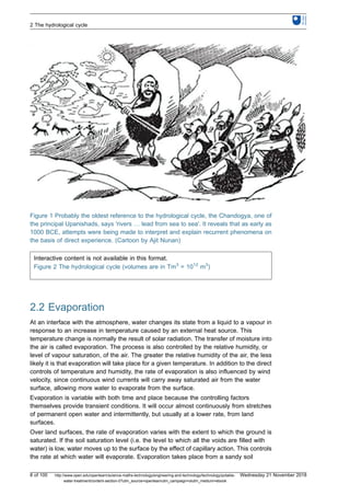
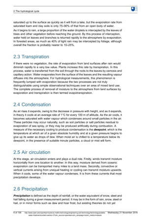
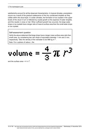
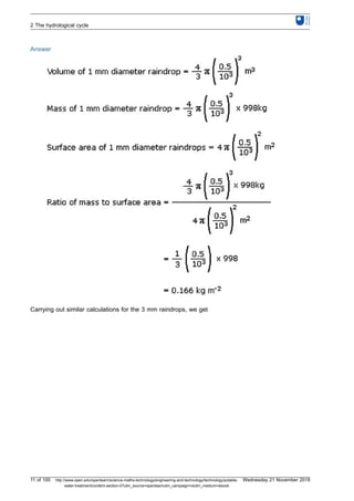
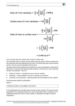
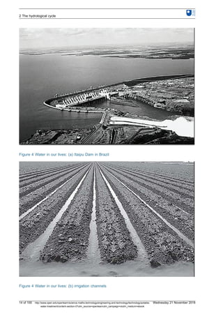
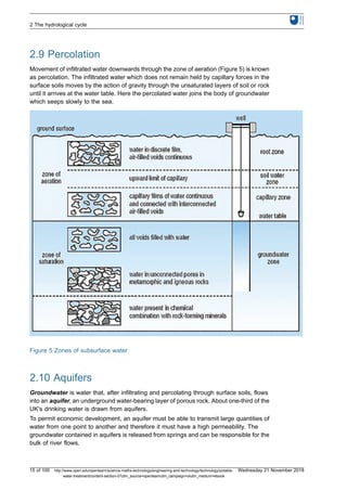
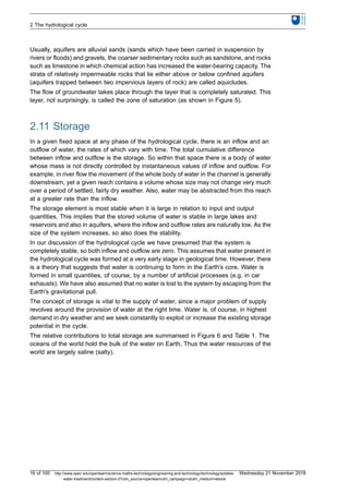
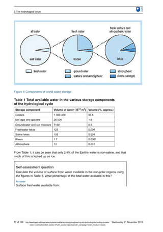
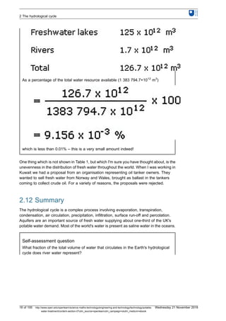
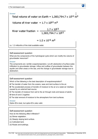
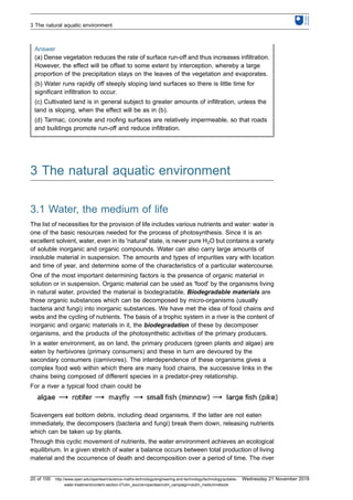
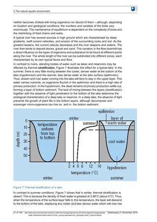
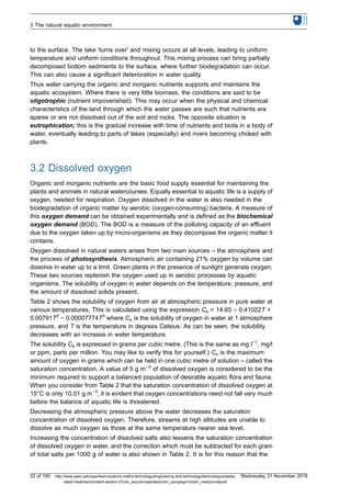
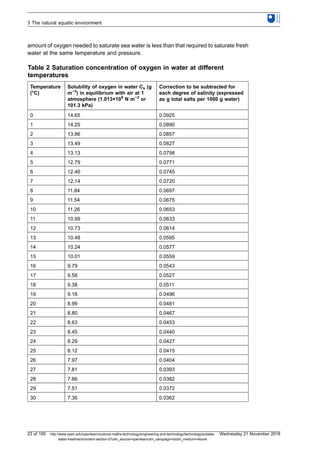
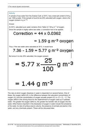
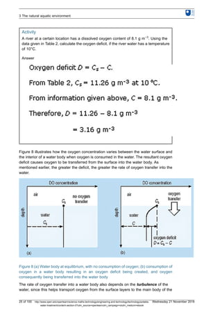
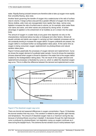
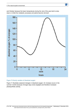
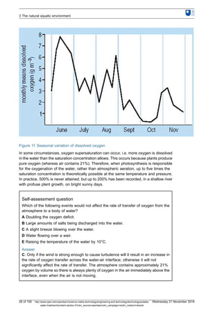
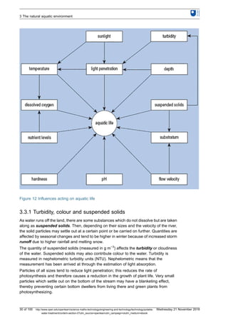
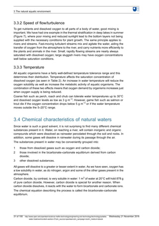
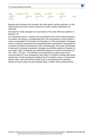
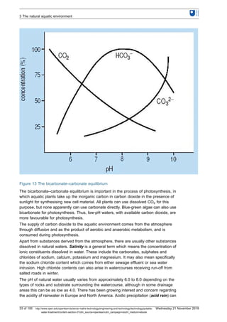
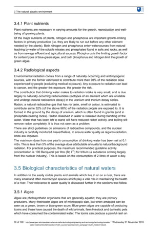
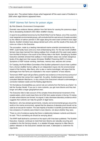
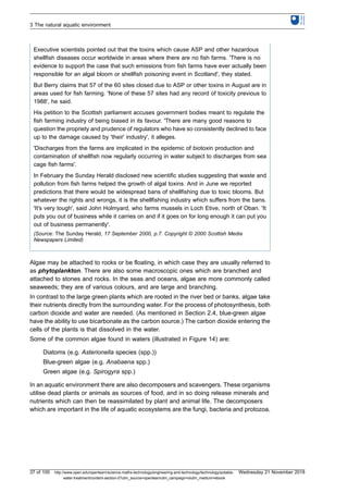
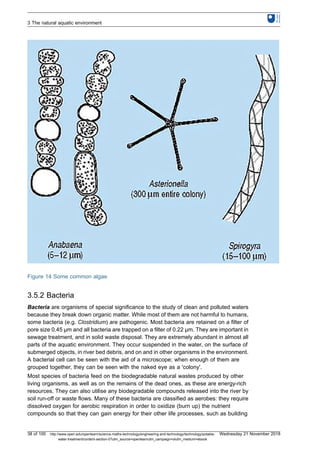
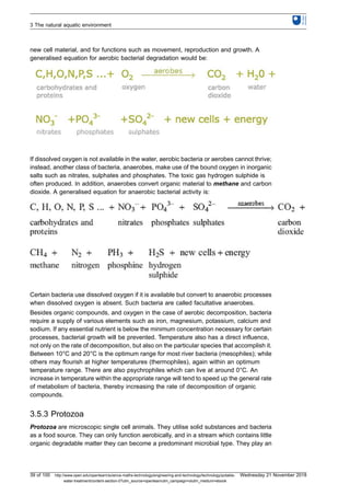
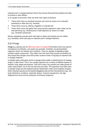

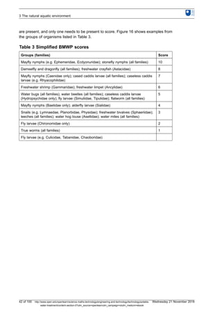
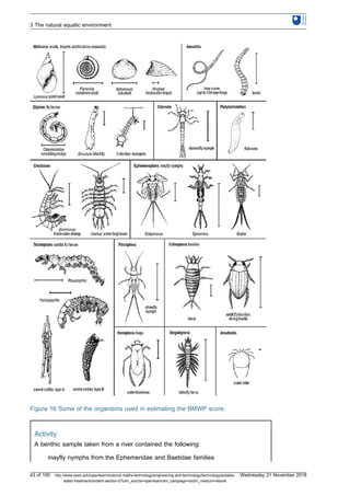
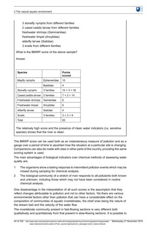
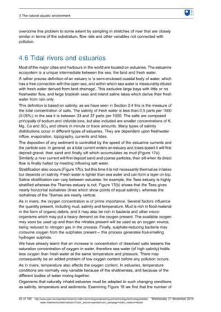
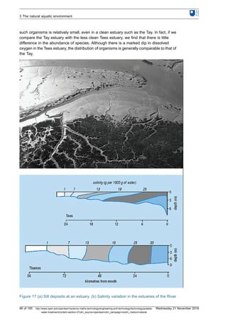
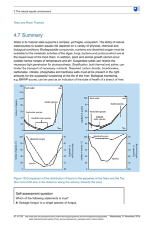
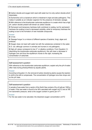
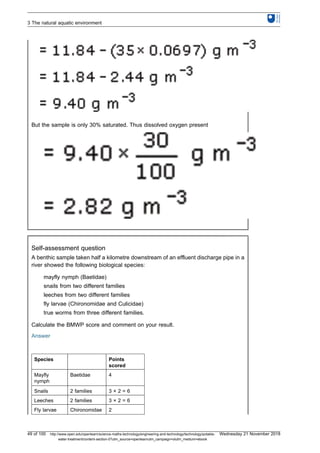
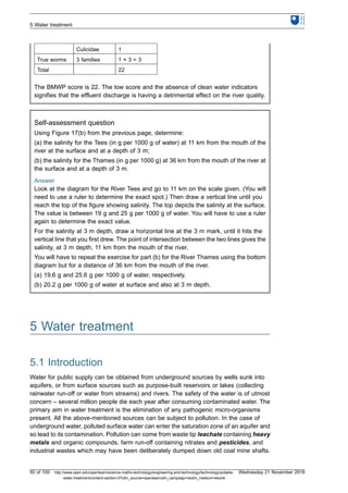
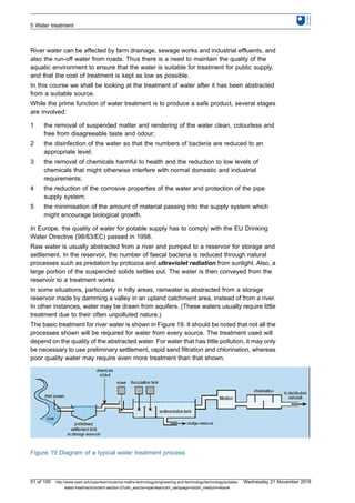
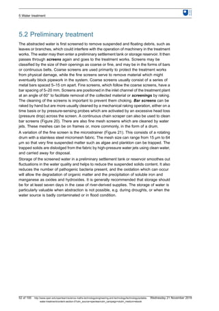
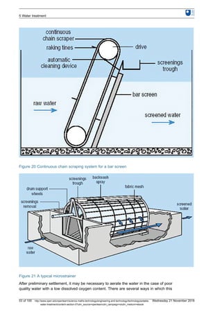
![can be done but the simplest is to allow the water to fall over a series of steps so that it is
able to entrain oxygen from the air. This is known as cascade aeration. In addition to
increasing the oxygen content, aeration also helps to liberate soluble gases, such as
carbon dioxide and hydrogen sulphide, and volatile organic compounds which could give
an undesirable taste to the water.
Aeration can reduce the corrosiveness of raw waters which are acidic due to their
carbonic acid content. When the water is aerated, some of the dissolved carbon dioxide is
displaced by the oxygen dissolving in the water. This causes some of the carbonic acid
that has been formed in the water by the carbon dioxide to be converted back to carbon
dioxide and water in order to maintain chemical equilibrium, as we discussed in
Section 2.4.
Aeration is also used to remove iron and manganese from solution. Iron and manganese
can cause peculiar tastes and can stain clothing. Iron is soluble in water only in the
absence of dissolved oxygen and at pH values below 6.5, when it is in the ferrous (Fe2+
)
state. Aeration converts soluble iron into its insoluble hydroxide [Fe(OH)3] which can then
be removed by filtration. Manganese can be removed in the same way.
After aeration, the water may be passed through a further fine screen before entering the
treatment works proper.
5.3 Coagulation and flocculation
Coagulation is always considered along with flocculation and is used to remove particles
which cannot be removed by sedimentation or filtration alone. These particles are usually
less than 1 μm in size and are termed colloids. They have poor settling characteristics and
are responsible for the colour and turbidity of water. They include clays, metal oxides,
proteins, micro-organisms and organic substances such as those that give the brown
coloration to water from 'peaty' catchment areas. The important property which they all
have is that they carry a negative charge and this, along with the interaction between the
colloidal particles and the water, prevents them from aggregating and settling in still water.
The particles can be aggregated by adding either multivalent ions or colloids having an
opposite (positive) charge. These are added as chemical coagulants.
Chemicals commonly used as coagulants in water treatment are aluminium and ferric
salts which are present as the ions Al3+
and Fe3+
. These positively charged multivalent
ions neutralise the naturally occurring negatively charged particles, thus allowing the
particles to aggregate. At high concentrations of aluminium or ferric salts, and in the
presence of sufficient alkalinity, insoluble hydroxides of aluminium or iron are formed (see
below). In the precipitation reaction the colloidal particles are enmeshed within the
precipitate and thus removed. The use of aluminium salts is not popular because of the
(unproven) scare about Alzheimer's disease. The move away from aluminium salts was
accelerated when aluminium sulphate was accidentally put into the treated water tank
for the town of Camelford in 1988. Most plants now use ferric salts.
If there is inadequate alkalinity in the water, it can be added in the form of lime (calcium
hydroxide Ca(OH)2) or soda ash (sodium carbonate Na2CO3).
5 Water treatment
54 of 100 http://www.open.edu/openlearn/science-maths-technology/engineering-and-technology/technology/potable-
water-treatment/content-section-0?utm_source=openlearnutm_campaign=olutm_medium=ebook
Wednesday 21 November 2018](https://image.slidesharecdn.com/potablewatertreatment-181208201208/85/Potable-water-treatment-OpenLearn-54-320.jpg)
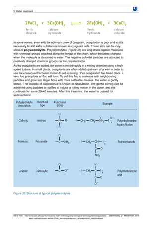

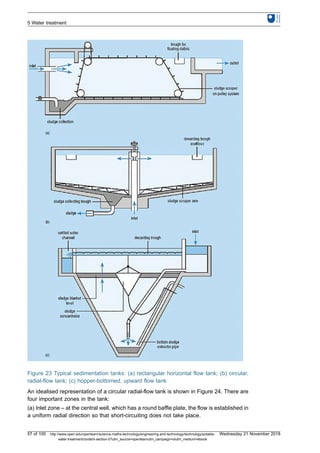
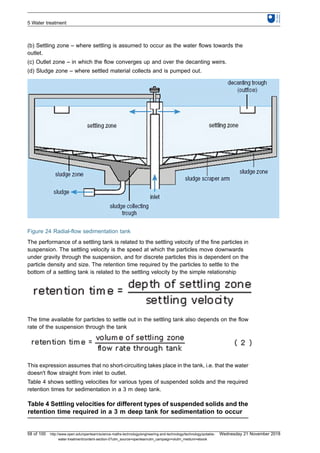
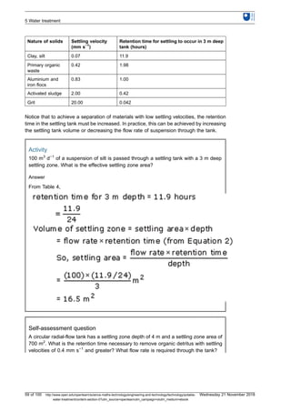
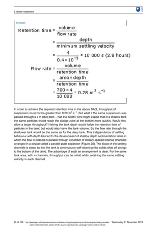
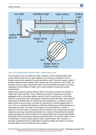
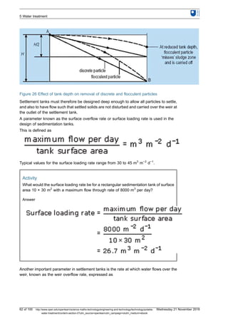
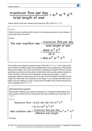
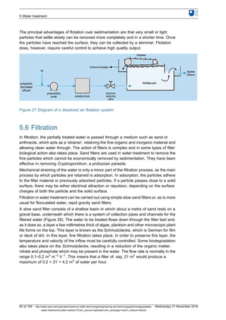
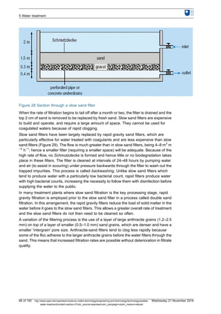
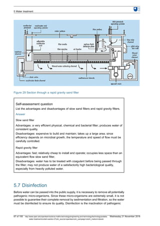
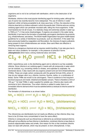

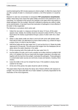
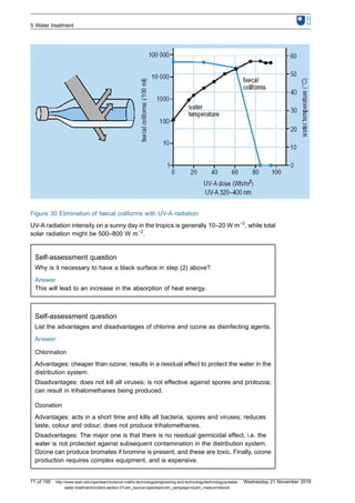
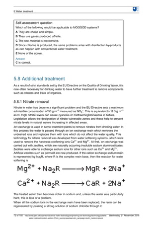
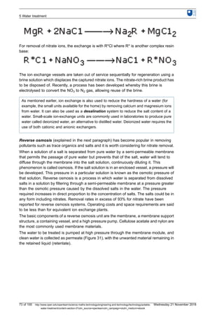
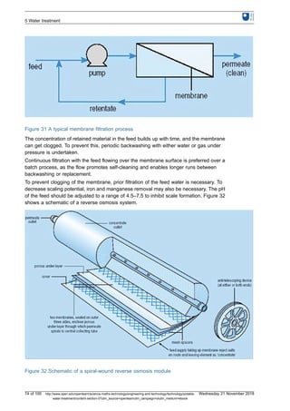
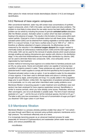
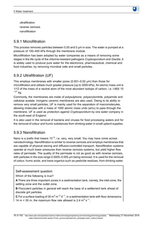
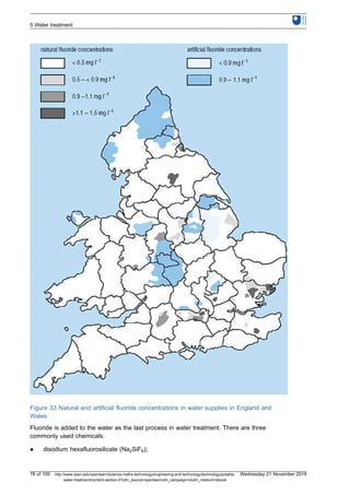
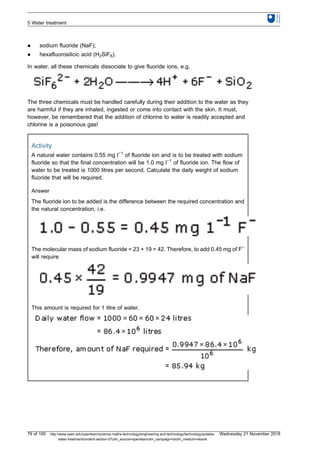
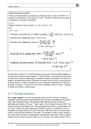
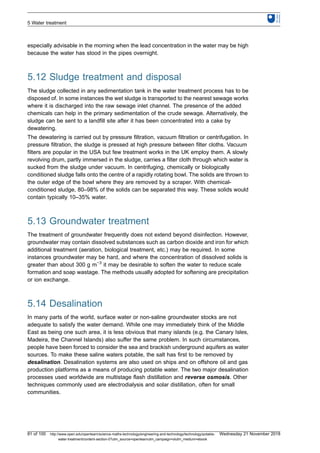
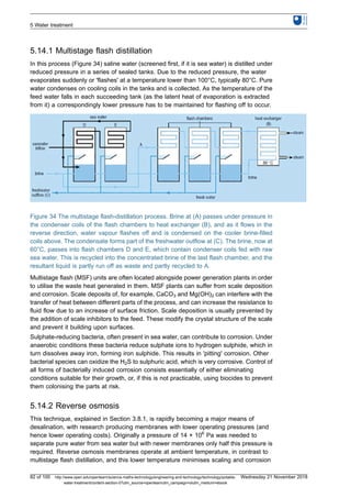
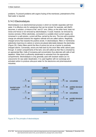
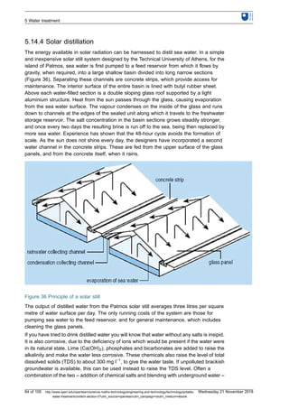
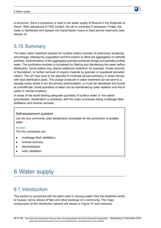

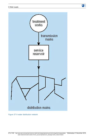
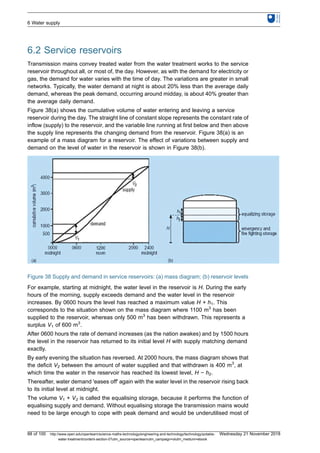
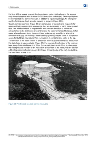
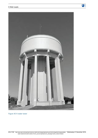
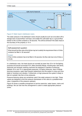
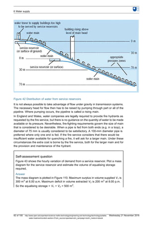
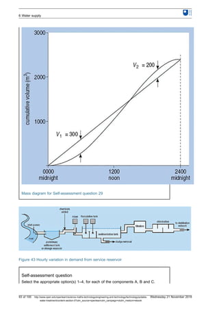
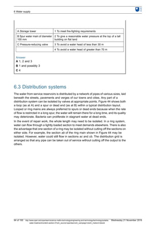
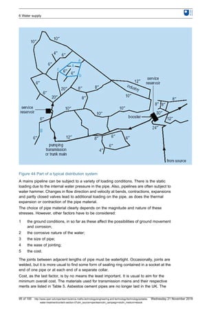
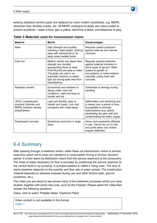
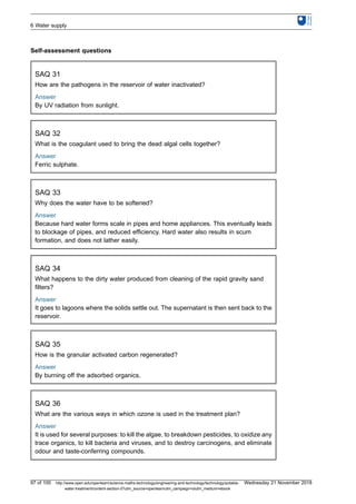


![Chapter 4 water and its management [autosaved]](https://cdn.slidesharecdn.com/ss_thumbnails/chapter4wateranditsmanagementautosaved-201011135301-thumbnail.jpg?width=640&height=640&fit=bounds)


![Polymer [ बहुलक ] Chemistry Notes PDF - Irfanullah Mehar - JJ Sir Chemistry.pdf](https://cdn.slidesharecdn.com/ss_thumbnails/polymerchemistrynotespdf-irfanullahmehar-jjsirchemistry-260210172118-3f9b37f7-thumbnail.jpg?width=640&height=640&fit=bounds)


