The document is a preface and introduction to the 8th edition of the Pneumatic Handbook, which provides a comprehensive reference on all aspects of compressed air. It covers topics ranging from basic principles of air compression to the design of compressors, tools, machinery, actuators, sensors and valves. The preface notes that while other technologies have advanced, compressed air remains important for power generation, transmission and control applications. It is intended to be a practical guide for engineers. The introduction acknowledges contributions from manufacturers and trade associations that assisted in its production.


![12 THE PNEUMATIC HANDBOOK
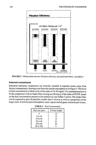
the pressure. Thus pressure, temperature and volume are interrelated. This relationship
can be expressed in the following form for a perfect gas (which assumes that the molecules
are perfectly elastic, are negligible in size compared with the length of the mean free path
and exert no force on each other):
PV = wRT
Note that an alternative form of the equation is:
PVs = RT
where Vs = specific volume in m3/kg.
The former is to be preferred.
Temp.
°C 10
-10 0
-5 0
0 1
5 1
10 1
15 2
20 2
25 3
30 4
35 6
40 7
45 10
50 12
20
1
2
2
3
5
6
8
11
15
19
25
TABLE 2 - Vapour pressure of moist air
I
1
1
2
2
4
5
7
10
13
17
22
29
37
(pressure in millibars)
Relative humidity in percent
14o l
2
3
5
7
9
13
17
22
30
38
49
50 I
3
4
6
9
12
16
21
28
37
48
62
6o I
4
5
7
10
14
19
25
34
44
57
74
z01
4
6
9
12
16
22
30
39
52
67
86
80
2
3
5
7
10
14
19
25
34
45
59
77
99
I 01
5
7
11
15
21
29
38
51
66
86
111
100
6
8
12
17
23
32
42
56
74
96
123
2O
10 i"
~."" i~"" II1111111
_,o~D..~;~I" 111111111
~ ;,~;."" i I1111111~
_.,or,.- I II111111!
1 2 3 4 5 10
I
I
I #
.~ "IA~IIV," .II~"
.I .,'llI.b~LV'
,l,':/]i"
,i ,~,i{,ki,
llj~-i/..
.i. l,,
~.,i,~~/"
qp-0.1 0.2 0.3 0.4 0.6 0.8 1.0
IIJ~lll .i" /.r ,, ~,~li
.%NIIIIII.,
r ~,'/" .,,'.,s,1511llll
'" IIIILI~/"L,'".1".,'," IIIIIIII
IIIIIIII
IIIIIIII
IIIIIIII
IIIIIIIi
IIIIIIII
IIIIIIII
IIiIIIII
IIIIIIII
i IiIIIIII
I IIIIIIII
I IIIIIIII
20 30 40 50 100g/re'
FIGURE 1 - Water content of air at different relative humidities.](https://image.slidesharecdn.com/pneumatichandbook-231106162117-d8c7a9ba/85/Pneumatic-Handbook-pdf-16-320.jpg)


![24 THE PNEUMATIC HANDBOOK
V2 V2
"J PdV = "j wRT dV =-wRTIoge(V,/V~)
Q
V
vi vl = PiVllOge(P:/Pl)
In practical units appropriate to a continuously working compressor:
W = 0.1 pl ql loge(P2/Pl)
where p is in bar, q is the flow rate in l/s and W is the power in kW.
In this case, the total work also includes the amount of heat extracted to maintain the
constant temperature.
Isentropiccompression
No heat is extracted in this case and the governing equation is:
PW = constant
The work done in compression and delivery is:
]
Q = VdP = wRT P2 7T'-_ 1
Pl
w
7-1
T--I
P2 S-f
P,V,[(--~-) -1]
As previously stated, the work done in practical units quoted above is given by:
[ ]
W = 0.1 plql - 1
Note that p~ and q~ refer to the inlet conditions of the compressor which is the usual way
of quoting performance.
Polytropiccompression
The equations appropriate to this type of compression are obtained by replacing yby n, the
polytropic exponent. This is more for practical purposes than a concept which has
theoretical justification, n is usually obtained empirically or by reference to the perform-
ance of similar compressors.
In continuous steady-state conditions it is impossible to attain a cycle approaching
isothermal. Most operations are closer to adiabatic. Isothermal represents the theoretical
aim and so the efficiency of a unit is often calculated on that basis.](https://image.slidesharecdn.com/pneumatichandbook-231106162117-d8c7a9ba/85/Pneumatic-Handbook-pdf-28-320.jpg)


![29
COMPRESSOR CLASSIFICATION
AND SELECTION
Some of the various methods of compressing gas and air are shown in Figure 1. See also
ISO 5390. Reciprocating compressors can be further classified as in Figures 2, 3 and 4
according to the arrangement of the cylinders.
Alternative forms of classification are possible, eg according to the motive power which
drives the compressor - electric motor, diesel or petrol engine; the type of gas to be
compressed; the quality of the compressed medium- the degree of freedom from moisture
and oil (as for example might be required in a food processing plant or for underwater
breathing supplies); the type of cooling - air or water and so on.
In choosing the correct compressor for a given installation, the following factors must
be taken into account:
• Maximum, minimum and mean demand. If there is an intermittent requirement for
air, but a large compressor set is needed to cater for peak requirements, the
Compressors
Dynamic I Dis~lacement
IEjector 1Radial 1Axial
Rotary
Onerotor I
~rLiquid
ing 1
iVane Screw
Reciprocating
Two rotors
1 ] 1 Trunkl Cr°SdS
1~
Lab~
Screw Roots
FIGURE 1 - Basic compressor types.
Diaph-]
rinth ragm](https://image.slidesharecdn.com/pneumatichandbook-231106162117-d8c7a9ba/85/Pneumatic-Handbook-pdf-32-320.jpg)


![42 THE PNEUMATIC HANDBOOK
built into the electric motor or driver (or hydraulic pump in the case of an hydraulically
operated machine, the main advantages offered by diaphragm compressors are:
• Complete gas tightness with only static sealing involved.
• Isolation of the gas being handled and thus the possibility of 100% oil-free
compressed gas supply.
The main limitations of the type are low delivery rates (to a maximum of about 30 l/min
in a single unit) and a limited compression ratio (to about 4.0). The latter limitation applies
particularly to mechanically operated diaphragms where the diaphragm itself is normally
of synthetic rubber. Hydraulically-operated diaphragm compressors may employ metallic
diaphragms and be capable of generating much higher pressures. A further method of
obtaining high pressure is to enclose the compressor and driver within a pressure vessel.
The vessel is pressurised to a level equal to that present in the inlet. The same pressure is
thus present on the underside of the diaphragm, reducing the pressure differential on the
diaphragm when working.
Rotary sliding vane compressor
A well-tried, mechanically simple design, Figures 17 and 18. The rotor and the vanes are
the only moving parts. The rotor is mounted offset in the casing; as can be seen, the
i~_~~o°'
As rotor turns, gas is Gas is gradually com-
trapped in pockets formed pressed as pockets get
by vanes smaller
Discharge
Compressed gas is pushed
out through discharge port
FIGURE ]7 - Working principle of a rotary vanecompressor.
FIGURE 18- Rotary sliding vane compressor.](https://image.slidesharecdn.com/pneumatichandbook-231106162117-d8c7a9ba/85/Pneumatic-Handbook-pdf-45-320.jpg)


![46 THE PNEUMATIC HANDBOOK
1.Suction: air at inlet pressure enters
compression chamber. Outlet ports sealed
off by female rotor hub.
3.End of compression: the entrapped air is
compressed to its maximum. Suction starts
as inlet ports are opened.
2.Compression starts: in- and outlet ports
closed off. Space between both rotors and
housing becomes progressively smaller.
Volume is reduced, pressure increases.
4.Delivery: recess in female hub uncovers
outlet ports and compressed air flows out.
r-] inletport [-7 Intakeair
I Outletport ~ Compressedair
FIGURE 23 (AtlasCopco)
FIGURE 24 (AtlasCopco)
bar. They are claimed to be suitable for pressures up to 10 bar. The rotors are of
comparatively simple construction in that they do not require helical machining so they
can be made from materials that would otherwise be difficult to manufacture, such as
stainless steel.](https://image.slidesharecdn.com/pneumatichandbook-231106162117-d8c7a9ba/85/Pneumatic-Handbook-pdf-49-320.jpg)
![48 THE PNEUMATIC HANDBOOK
=
A
Principal parts of a turbocompressor.
Volute
Diffuser
Impeller
__ _ -~
Axial impeller.
Centrifugal impeller
FIGURE 26
/
__S
Mixed flow impeller
Inletflange Dischargeflar~e
aphragm
~ I Diffuser Volute
Guidevane~ ~M~~" E~~ I Thrustbalancing
Thrust
beari
-[~-~~ -hf// I /-~ ----ill~~~j~bearing~~
M~ Shaft Impeller V///,//_~.~
a C°Xupling
UUUd
ih]earing II ' I Seal
Casing ~/f/'~~~~~J
FIGURE 27 - Sectional view of a typical five-stage horizontally-split centrifugal compressor.](https://image.slidesharecdn.com/pneumatichandbook-231106162117-d8c7a9ba/85/Pneumatic-Handbook-pdf-51-320.jpg)

![50 THE PNEUMATICHANDBOOK
a
ut/Quantity
,,
I I
, .
[ Quantity delivered / Efficiency
-- envelopes
iL~ Working range --*- Curves for -----'-]-'-.,~ /
Min. Max different speed~/f/~f~
FIGURE 29- Workingrangeof
a dynamiccompressor. Design --. __ 4L-//--~--/~ ) /~
,. value /
Surging //~%~ I~
/////
Quantity delivered
FIGURE 30- Efficiencycurvesof a
dynamiccompressor.
As in other types, compression can take place in stages. The pressure ratio which can
be reached in a single stage is limited by the maximum peripheral speed of the impeller.
Centrifugal machines normally generate a pressure ratio per stage of 1.5 to 2.0, although
with improving technology pressure ratios are increasing. A pressure ratio of 6 can
obtained in a 2-stage design. In an axial compressor the compression per stage is limited
to about 1.3;they may have up to 20 stages. Centrifugal units may incorporate intercooling
between stages, axial units rarely do. Single-stage centrifugal units are frequently used as
blowers and exhausters.
Shaft speeds are high- 20 000 r/min is common in industrial units. 100 000 r/min is
found in aircraft engines. At these speeds rolling bearings are unsuitable; plain or tilting
pad bearings are necessary. Figure 28 shows a modern single-stage centrifugal unit. It can
be seen that the actual compressor forms only a small part of the air end; the major part
of the machine is in the step-up gear and the cooler.](https://image.slidesharecdn.com/pneumatichandbook-231106162117-d8c7a9ba/85/Pneumatic-Handbook-pdf-53-320.jpg)


![56 THE PNEUMATICHANDBOOK
for low speed compressors a value of n = 1.3 is often used. The stage pressure ratio is
determined by the pressure set by the delivery valves.
The stage temperature rise is
n-1
T2 = TI (P-~l) n
The power absorbed by the stage is
W = 0.1plql
See also Figure 3.
n-1
n [( p_.~l
) n ]
n-1 --1
The inlet pressure and temperature of the inlet to the next stage depends on the degree
of interstage cooling. In practice perfect cooling down to the inlet temperature is not
possible. The cooling system necessarily absorbs power either in driving a fan or
circulating the cooling water and this must be taken into account in determining the overall
power required. Ten to 15% of the input power should be allowed for cooling purposes.
Volumetric efficiency
One characteristic of a reciprocating compressor is the clearance volume that remains in
the cylinder at top dead centre after the delivery stage is complete. This is usually
expressed as a proportion of the swept volume and typically has a value of 0.06 to 0.12.
This volume is not discharged but expands until it occupies the cylinder volume. The effect
of this is to modify the shape of the indicator diagram as in Figure 4. Theoretically this
expansion represents no loss of energy if the index of expansion equals the index of
compression (bearing in mind that the compression is isentropic and reversible, so the
energy used is reclaimed).
Pl d b
I
I
I
I
L , c
~.zS So_ ~= S i
"
._ zS" So S i
FIGURE 4 - Ideal and practical compressiondiagram. Theoretical diagramabdea.
Practical diagramabdfa. Suction period: theoretical Si, practical Si".
Clearance volume: theoretical So,practical So".](https://image.slidesharecdn.com/pneumatichandbook-231106162117-d8c7a9ba/85/Pneumatic-Handbook-pdf-59-320.jpg)
![COMPRESSOR PERFORMANCE 57
The volumetric efficiency of the compressor is a function of the first stage geometry,
although for design purposes the separate stages can be separately analysed. It is given by
1
[ {(P2) mZI }]
rlv=K l-Vc ~ 7_.2 l
pl and p2 are the intake and delivery pressures in the first stage.
K is a factor depending on valve losses, intake air heating, leakage and pressure ratio. K
can be taken as 0.96 for an initial estimate.
Vc is the relative clearance volume.
Z~ is the compressibility factor at intake.
Z2 is the compressibility factor at discharge.
m is the index of expansion, which as a first approximation is equal to y, the isentropic
index.
The expansion index varies with pressure according to the following:
For the first stage m = 1.20 For the fourth stage m = 1.35
For the second stage m = 1.25 For subsequent stages m = ?
For the third stage m = 1.30
A high volumetric efficiency is not necessarily better than a lower one; its significance lies
in the calculation of the compressor capacity. If, however, the low efficiency is caused by
leakage, then the design is at fault.
Other positive displacement types (screwand vane)
One general feature of these types is that they rely on the position of the delivery port to
determine the built-in pressure ratio. (It would be more correct to refer to a built-in volume
Operation above
design pressure
_Discharge pressure_
•..~Design pressure
"~':'~" •
" ~ ...... ~ ....... '-'.:.~........ .,-i.i.,.,9 ~
Volume
Operation below
design pressure
,~L-i Design pressure
~-
................................
. . . .
r.~,_ Disc~'
1arg
~ ~essure
"'.....
J
Volume
Operation at
design pressure
l l
I; Design pressure
_
..................................
~..~..~scharge)
...
[,
Volume
FIGURE 5- Operation at pressures deviating from the built-in pressure ratio.](https://image.slidesharecdn.com/pneumatichandbook-231106162117-d8c7a9ba/85/Pneumatic-Handbook-pdf-60-320.jpg)

![COMPRESSOR PERFORMANCE 59
Note that there is no clearance volume as in reciprocating unit. Figure 6 shows a typical
set of volumetric efficiency curves for a modern screw.
The theoretical power can be found, as in the case of a reciprocating compressor, from
n-I
n [( P_~_t2
) n ]
W = O.lpiql n- 1 -1
It might be thought that the injection of massive quantities of oil into the compression
chamber (typically, the ratio of the mass flow of the oil to that of the air is of the order 10:1)
would result in an isentropic index close to unity. In fact, the flow velocity is so great that
the actual heat transfer between air and oil takes place in the relatively static conditions
in the oil reclaimer rather than in the compression chamber. The calculations on power can
best be done by assuming isentropic compression and modifying the index from practical
tests. The isentropic efficiency depends on the particular screw design. Typical curves are
given in Figure 7.
o
o
o ~ ~'-
o
~" ~ e-
~I ~.l .=
i 1 i(
c
..._.-: Design point
i
Flow
FIGURE 7 - Constant efficiency curves for the rotating screw compressor.
Performance of vane compressors
The swept volume of these units is readily calculated from the crescent area between the
vanes.
The same remarks about isentropic efficiency apply as for screw compressors. When
these units are oil flooded, oil churning represents one of the main power losses. There is
little leakage across the outer edge of the vanes, because centrifugal force keeps them in
intimate contact with the cylinder. There is, however, leakage across the ends of the vanes,
which are not well sealed by the oil.
Performance of Roots and similar types
There is no built-in pressure ratio in these units and their efficiency is low, see Figure 8.
Some improvement in efficiency is possible by adjusting the ratio of the volume in the](https://image.slidesharecdn.com/pneumatichandbook-231106162117-d8c7a9ba/85/Pneumatic-Handbook-pdf-62-320.jpg)


![62 THE PNEUMATIC HANDBOOK
Constant head
plus friction
,,
~ Friction
Quantity delivered :
FIGURE 11
the compressor can be changed, eg by means of a butterfly valve installed preferably near
the compressor inlet or near the discharge. Other methods of adjusting the compressor
characteristics, and hence the pressure and capacity, include the use of adjustable diffuser
vanes and adjustable inlet guide vanes.
Estimation of compressor performance with altitude
A number of factors combine to modify the performance of a compressor at altitude.
Performance tests should always be used as the primary source of information. Where the
results of such tests are not available, an estimate based on theoretical considerations can
be made.
Refer to Table 6 in the chapter on Properties of Air and Gases, for details of the standard
atmosphere. Note that the density, temperature and pressure all fall with increasing
altitude. If the compressor is designed to produce a given amount of air at a given pressure
at sea level its performance at altitude will be affected, not only because of the change in
inlet conditions but also because it will no longer be able to operate at its optimum design
efficiency.
There are two ways of looking at the change with altitude: when operating the same
compressor at the same speed and same delivery pressure, the power to run it will be less
at altitude; when it is desired to obtain the same useful output, the power required will be
greater. The actual energy content of the compressed air is measured by the mass flow
rather than the volume flow at inlet conditions, so a calculation of the extra power required
at altitude can be made from an alternative form of the power equation:
W = 0.1 wRT
n-I
n [( P_~12
) n ]
n-I
-1
As an example one can use this equation to compare the power at altitude with the power
at sea level, when delivering air at a constant mass flow and a constant delivery pressure](https://image.slidesharecdn.com/pneumatichandbook-231106162117-d8c7a9ba/85/Pneumatic-Handbook-pdf-65-320.jpg)


![88 THE PNEUMATIC HANDBOOK
One should always attempt to design the pipework system so as to avoid undesirable
frequencies. This is difficult, and it may turn out that when the installation is finished, it
is unexpectedly noisy. One may then be faced with having to apply remedial treatment;
this can be done by adding acoustic lagging to the outside of the pipes. Lagging should be
made of a porous material such as glass fibre attached to the pipe, with an outer layer of
dense cladding such as aluminium, steel or leaded plastics.
Intake valves
Compressor control systems that rely on throttling the intake may result in a high
frequency note under part-load, partially throttled conditions. It may be necessary in this
case to try a different valve.
Compressor casings
Casings can be very efficient radiators of noise, particularly if, in an attempt to reduce cost,
the thickness has been reduced to a bare minimum. The thicker the sections and the more
inherent damping there is in the material the better are its acoustic properties. Cast iron is
a very good material in this respect. It is not generally very successful to try the application
of acoustic cladding to a casing after manufacture. It is likely to be expensive and may also
act as a thermal insulator, raising the temperature of the compressor. Water coolingjackets
act as a natural noise barrier and it may be better in some circumstances to use water, rather
than air, cooling.
An acoustic enclosure is likely to be the most effective form of noise barrier. Practically
any required attenuation can be achieved by enclosure. Twenty five dB is perfectly
possible whereas techniques of noise reduction at source will only give about 5 dB. In
designing an enclosure, reference can be made to the Handbook of Noise and Vibration
Control. By far the best enclosure is one made of solid brickwork or some other heavy
material. This is not practical for a compressor which needs to be moved, so the next best
radiator w l If Y If If f y li L • II
a) Baffled duct b) Straight duct with "splitters" c) External baffle giving
l-~] 180°fl°wturn
- - ~
FIGURE 2- Treatment of cooling air passages.](https://image.slidesharecdn.com/pneumatichandbook-231106162117-d8c7a9ba/85/Pneumatic-Handbook-pdf-91-320.jpg)


![COMPRESSOR CONTROLS 95
"i , . ]
A-Throttle valve
B-Low-pressu re stage
C-Intercooler
D-High pressure stage
E-Non-return valve
F-Aftercooler
G-Blow-off valve
H-Blow-off cooler
J-Servo-valve
K-Solenoid valve
L-Temperature switch
M-Regulator
FIGURE 7 - Capacity unloading of screw compressors. (Atlas Copco)
As the compressor is off-loaded, the valve moves progressively opening up ports which
connect the compressed air back into the inlet. This form of control is only suitable when
the compressor is driven by a constant speed device such as an electric motor. Speed
control is usually preferable, as well as being simpler.
Multi-pressure capability for screw compressors
It is sometimes convenient to supply a compressor with different pressure capabilities to
meet the varying demands of the plant hire industry. It is clearly not possible in an
installation with a fixed prime mover to supply a range of pressure capabilities while
delivering the same output. However it is possible in a limited way to exchange delivery
volume and pressure. This can be achieved by what amounts to a shortening of the L/D
ratio of the screw elements. A portion of the inlet length of the screws can be by-passed
through one of a series of passages in the compressor casing, which vent some of the inlet
air according to the desired pressure setting. The operating condition is set initially (which
can be key locked to avoid improper use). Thus, in one particular compressor it is possible
to have the following variations:
Delivery in l/s Gauge pressure in bar
360 6.8
314 8.5
276 10
Unloading and speed control system in an engine driven screw compressor
Compressor air output is controlled by a combination of an unloader valve which regulates
the amount of air entering the compressor and a speed controller which varies the engine
speed. An engine is not, ofcourse, capable of running down to zero speed; typically a diesel
engine can operate down to 50% of its maximum rated speed and still give a useful output,
say from 2000 r/min down to 1000 r/rain. It could still idle at less than 50% but the torque
obtainable would not be sufficient to turn a screw. Usually the engine speed is reduced first](https://image.slidesharecdn.com/pneumatichandbook-231106162117-d8c7a9ba/85/Pneumatic-Handbook-pdf-98-320.jpg)


![AIR RECEIVERS 105
where VR is the receiver capacity in m 3
V is the air requirement for a given operation in m 3
AP is the pressure drop (bar) experienced in the receiver during the operation
Po is atmospheric pressure in bar
If the operation is identified by a flow rate q in m3/s over a time t, this equation can be
rewritten as:
qt AP
= [2]
VR Po
These equations assume that no air is being added to the receiver during the operation.
If the compressor is simultaneously supplying air at a rate qc m3/s, the latter equation
becomes:
(q-qc)t AP
= [3]
Vl~ P,,
In the above example of intermittent use, the acceptable pressure drop has to be chosen.
Taking two possible choices for the maximum pressure, case (a) 20 bar and case (b) 35 bar,
both from compressors delivering 10 m3/min.
Applying equation [3] to case (a)
(60-10) x10 _ 20-7
Vl~ 1
so VR = 500-- 13 = 38.5 m 3 and the actual volume of the receiver will be 38.5/21 =
1.83 m 3.
Similarly for case (b) V~ = 18 m 3 and the actual volume of the receiver will be
18 + 36 = 0.5 m 3.
In deciding which choice to make the most economical solution is when the total cost
of the compressor, receiver and fuel is a minimum.
Receiver volume calculations in automatic start/stop control
If the control system involves stopping and starting of the motor, then a receiver much
larger than that for automatic unloading is required so as to avoid too rapid a cycling of
the controls. The primary requirement is that the receiver must be sized so that no more
than about ten starts per hour, evenly spread, take place; this is so that damage to the starter
system and the motor windings is avoided. The spread of pressure should be as large as
can be tolerated to further reduce the number of cycles. The compressor manufacturer will
normally calculate the correct receiver size based on the control system used.
Equation [3] can be rewritten as
qc (1 - ~) ~tP,,
VR = [4]
AP
where ~ = q/qc
and, in this instance, t is the time between successive starts of the compressor
is the actual air demand as a fraction of the amount delivered by the compressor. It](https://image.slidesharecdn.com/pneumatichandbook-231106162117-d8c7a9ba/85/Pneumatic-Handbook-pdf-108-320.jpg)
![106 THE PNEUMATIC HANDBOOK
turns out that the worst condition for frequency of stops and starts is where ~ =0.5, ie when
the demand is half the supply. If the demand is greater or less than a half, the number of
stops is less frequent so this condition is usually taken as the design point. Replacing V by
0.5, equation [4] becomes:
qctPo
VR ~
4AP
For t = 6 minutes and AP = 1, the relationship becomes;
VR = 1.5 qc.
Compare this with the formula for the receiver size quoted above for unloading systems
of control:
VR = 0.1 qc
This comparison between the two values for the volume indicates the importance of
assessing the correct receiver size to meet the requirements of the system.
Air receiver legislation in the U.K.
There is a large legislative framework governing the whole area of receiver design and
certification which needs much study before it can be applied with confidence.
The Health and Safety at Work Act 1974 places a general duty on a number of persons
involved with matters of safety; the duties are shared by designers, manufacturers,
suppliers, importers employers, employees etc. Regulations in specific branches of
industry have been made under the Act. The primary document on pressurised systems (of
which air receivers are usually the most critical element) is The Pressure Systems and
Transportable Gas Containers Regulations 1989 (SI 1989 No 2169), all of which are now
in effect. These Regulations implement EC Directive 76/767/EEC. The Health and Safety
Executive have prepared a Code of Practice- Safety of Pressure Systems- which gives
practical guidance on these Regulations. The British Compressed Air Society have gone
further and have produced a comprehensive set of Guidance and Interpretation Notes
which should be studied alongside the two official documents.
It should be noted that these Regulations repeal much of the Factories Act 1961 insofar
as it related to pressure vessels, however vessels already in use and bearing markings made
in accordance with the Act will not have to be changed unless they are modified
subsequently.
The Regulations do not give detailed design methods (reference must be made to the
appropriate Standards for these) but are concerned with ensuring that pressure systems
falling within their scope are properly made, inspected, maintained and marked so as to
safeguard those persons affected. The intention is to prevent the risk of injury from the
release of the stored energy in a compressed air system. They are in fact wider in scope
than compressed air and encompass steam, gases and mixed liquids and gases. The
complete system includes the pressure vessels, pipework and any protective devices,
where the pressure is in excess of 0.5 bar. If the complete system does not incorporate an](https://image.slidesharecdn.com/pneumatichandbook-231106162117-d8c7a9ba/85/Pneumatic-Handbook-pdf-109-320.jpg)


![AIR RECEIVERS 109
Class II- The design pressure shall not exceed 35 bar and the product of design pressure
and internal diameter shall not exceed 37 000 bar mm.
Class III - The design pressure shall not exceed 17.5 and the product of design pressure
and internal diameter shall not exceed 8800 bar mm.
Wall thicknesses
Simple theory for determining the thickness of a cylinder subject to internal pressure
produces the relationship:
pd
t = [5]
2f-p
where: t is the wall thickness
f is the nominal design stress
p is the internal pressure
d is the internal diameter
This equation is true for any system of consistent units.
The equivalent equation given in BS 5169 states that the thickness of the shell plate shall
not be less than
pd
t = 20fJ-p + 0.75 [6]
where: t is the thickness of the wall in mm
p is the pressure in bar
d is the inside diameter of the shell in mm
f is the design stress in N/mm 2
J is the joint factor, which may vary from 0.4 to 1.0
0.75 is the allowance in mm for corrosion,
providing that in no case shall the thickness be less than 4 mm, or, in the case of Class III
receivers where the internal diameter does not exceed 300, the thickness shall be not less
than 2.5 mm or 0.01 D, whichever is the greater.
Where the ultimate tensile stress (uts) is known, the design stress is
f = uts / 3.5
Design of ends
Ends shall be hemispherical or semi-ellipsoidal and may have manholes or hand holes. In
the case of Class II and Class III receivers, and Class I receivers where the internal diameter
does not exceed 600 mm, flat ends are permitted. If semi-ellipsoidal ends are chosen, the
ratio of the major axis to that of the minor axis shall not be greater than 2.25:1.
For hemispherical ends the thickness of the end plate shall not be less than
pR
+ 0.75 [7]
k. = 20fJ- p
where: R is the radius of the hemisphere
is the thickness of the end](https://image.slidesharecdn.com/pneumatichandbook-231106162117-d8c7a9ba/85/Pneumatic-Handbook-pdf-112-320.jpg)
![110 THE PNEUMATIC HANDBOOK
oi
i t"
"(" !
L; - . . . . . . .
FIGURE 2 - Pressure vessel end showing a closed end to the right
and a typical opening on the left.
For other concave shapes
pdK
= + 0.75 [8]
20fJ
In both cases J = 1 for endplates made of one piece, and for plates made of more than
one piece J is the appropriate factor obtained from the tables in the Standard. K depends
on the ratio (h + t )/D, where h is the height of the height of the dished end and D is the
outside diameter. K is read from Figure 3. In no case shall the thickness be less than that
of the cylinder.
In some cases it is permissible to have flat ends rather than concave ends for an internal
diameter not greater than 600 mm.
4.0
3.0
K
20
":: :i!t:--~th.:J....1
...........~,,!@=~
[_~." I~ !'!i~[][li:g!~]~;i~!III] -:r,]'.H~,
O.I 015 0.2 025 0.3 0.35 04 045 0.5
/~+te
D
FIGURE 3](https://image.slidesharecdn.com/pneumatichandbook-231106162117-d8c7a9ba/85/Pneumatic-Handbook-pdf-113-320.jpg)
![AIR RECEIVERS 111
For flat plates welded to the cylinder
te = / pd2
q CS
where:
+ 0.75 [9]
S is the minimum tensile strength of the plates
C = 14.3 for unflanged end plates or = 17.4 for flanged end plates.
Openings in shells and plates
Openings have to be provided in receivers for the purpose of inspection, see Table 2. All
openings have to be ring reinforced to strengthen the vessel in the region of the material
removed. A good design guide is to make the ring from as much material as was removed.
Refer to the standard for details.
TABLE 2 - Examination holes and manholes for air receivers
Vessel
internal
diameter
mm
0 to 300
> 300 to 450
> 450 to 800
>800 to
1500
Over 1500
Length of
cylindrical
section
mm
0 to 1500
0 to 1500
0 to 1500
> 1500 to
2000
Over 2000
0 to 2000
Over 2000
Unlimited
Number of openings (minimum)
Small Large
sight sight Hand Head Man-
hole hole hole hole hole
2 0 0 0 0
0 2 0 0 0
see note 1
0 2or 1 2or 1 0
see note 2 see note 3
0 0 2 or 1 2 or 1
see note 2 see note 3
0 0 see note 4
0 0 2or 1 0
see note 2 see note 3
0 0 see note 4 0
0 0 0 0 1
Note 1:Wherethe lengthis morethan 1500mmadditionalsightholesmaybe provided.
Note2: Inthecaseofa cylindricalbodytheholesshouldeachbesitedneartheends(withinsightofthe longitudinaljoint
and the base)or elsein the centreoftheends.
Note3: A singleheadholeor handholewhichshouldbe situatedin the centralthirdof vessellength.
Note4: The numberof inspectionholesshallbe increasedaccordingly.Fora lengthof lessthan3000mmit is, however,
sufficienttositeaheadholeinthecentreofthecylindricalbody.Onthecylindricalbodythegreatestdistancebetweenthe
headholesshallnotexceed3000mm,andbetweenhandholes2000ram.Thelattershalleachbe locatedeithernearto or
in the ends.
Design in accordance with BS EN 2186
The alternative procedure of this document is confusing to the designer used to the earlier
standards because the notation and the way in which the equations are expressed are
different. Air receivers made in accordance with this standard are of simple construction,](https://image.slidesharecdn.com/pneumatichandbook-231106162117-d8c7a9ba/85/Pneumatic-Handbook-pdf-114-320.jpg)
![112 THE PNEUMATIC HANDBOOK
primarily welded and serially made. If possible this standard is preferred provided that the
conditions it covers are met.
The normal design stress is the lower value of 0.6 Roy or 0.3 Rm ,where tL,v is the
guaranteed minimum tensile yield strength and Rm is the guaranteed minimum tensile
strength.
The normal thickness (e) takes account of corrosion and tolerance in the specification
of the material thickness.
e _> ec+s+c
where ec is the calculated thickness
s is the corrosion allowance
c is the absolute value of the negative tolerance on the material thickness.
There may also be an extra allowance to cater for thinning in production.
PDo
ec =20f+p Kc [10]
In this relationship,
Do is the outside diameter in mm
P is the design pressure in bar (< PS, the maximum working pressure)
f is the nominal design stress in N/mmz
I~ is a calculation coefficient which depends on the welding process and the
inspection method (varies from 1 to 1.15).
For hemispherical ends
PS Do
ec 40f + PS
For flat ends without openings
e=C DJ PS
10f
[11]
[12]
where: C is a coefficient determined from a consideration of the end design
D = design diameter of the flat ends. For a simple welded end this is the internal
diameter.
The above treatment is only an outline of the general approach to the design of air
receivers. Any serious designer should study the full standards; they contain a great deal
of useful material. A competent person, as defined in the Regulations must demonstrate
a full understanding of the appropriate standards.](https://image.slidesharecdn.com/pneumatichandbook-231106162117-d8c7a9ba/85/Pneumatic-Handbook-pdf-115-320.jpg)


![TABLE 1 - Typical cooling water requirements (litres per cubic metre free air)
Component Pressure
bar (gauge)
Compressors:
Cylinder jacket:
Single-stage
Two-stage
Intercoolers:
In series with cylinder
jacket
Separate
Aftercoolers:
Single-stage
Two-stage
2.8
4.2
5.6
7.0
5.5 to 8.5
5.5 to 8.5 4.5
5.5 to 8.5
5.5 to 8.5
5.5 to 8.5
16°C
0.8 to 1.0
1.2 to 1.3
1.45 to 1.95
2.0 to 2.4
1.6
5.4
4.0
6.5
4.0
Water temperature
21°C
1.15
1.6
2.1
2.6
1.8
6.5
4.85
7.3
4.85
I oc [
1.3
1.8
2.25
2.75
1.95
5.7
8.5
5.7
HEAT EXCHANGERS AND COOLERS 123
32oC
1.45
1.95
2.4
2.9
2.25
7.3
6.5
9.7
6.5
the water in the jacket. This is not a particularly efficient form of cooling and can
be supplemented by an external intercooler
• Injection cooling involves spraying a suitable liquid into the return channel of the
compressor stage. In the case of a refrigeration compressor, the refrigerant itselfcan
be used. For air compressors, water can be used, providing that the increase in water
vapour can be tolerated.
• Intercooling, which may be placed between any two of the stages (eg between the
third and fourth stage of a six stage machine).
Shell-and-tube coolers
Shell-and-tube heat exchangers can adopt a variety of different forms, as in Figure 1. The
=],|
|
'l
I
l
Shell-and-tubeheatexchanger,1'1,counter-current
t
tl. !
u n
,t',
II[~ll 1:2 shell-and-tubeexchanger
2:4 shell-and-tubeexchanger
Cold
A Cold ---~ 2 _ hot
~ Cross-flow
B hot
FIGURE 1 -- Configurations of shell-and-tube heat exchangers.](https://image.slidesharecdn.com/pneumatichandbook-231106162117-d8c7a9ba/85/Pneumatic-Handbook-pdf-126-320.jpg)


![136 THE PNEUMATIC HANDBOOK
lagged. The descriptions isothermal and isentropic would have no relevance unless the
fluid were compressible, that is unless it were possible to define a relationship between its
pressure and its volume. It is usual to study first the formula for pressure drop that would
apply to an incompressible fluid because it turns out that this applies equally well to many
important cases of compressible flow. This equation is known as the Darcy formula or the
Darcy-Weisbach formula:
AP= pfLv2 [1]
2D
where the variables have their usual definitions.
Another form of the equation, which is usually found when dealing with the flow of
liquids, is:
fLv2
h=
2g
In this formula h is the loss of head in metres. The concept of a head loss is readily
understood in liquids, where pressure can be equated to the height of a liquid column. In
gases it is not so relevant. The preferred relationship, therefore, is equation [1].
The variable f is known as the Darcy friction factor, which has to be obtained
experimentally. The formula applies whether the flow is laminar or turbulent, but always
with a value of f appropriate to the flow regime. Fortunately, a large number of tests have
been done on pipes of various materials, sizes and internal roughnesses, so it is possible
to look up the value of f on a chart when certain other parameters are known. The main
factor governing the value of f is the Reynolds number for the flow. It does not matter
whether the fluid is a gas or a liquid; if the Reynolds numbers are the same, the value of
f will be the same.
The complete isothermal formula
The equation for compressible flow, which takes into account that the pressure at the end
of a long pipe may be significantly smaller than that at the beginning, is:
AP pfv2 dv
= + pv
L 2D dL
This is the same as the Darcy equation, with an added expression to allow for the drop
in pressure necessary to decelerate the flow. The extra expression is significant for pipes
with a large pressure drop.
The solution of this equation is usually written as"
w: = pA2 P ~- P22 [2]
tL/D+21og~(PI/P2) Pi
w is the mass flow.
This is correct for any consistent set of units. In particular, in conformity with the standard
nomenclature, it applies where L, D and A are expressed in metres, P in N/m2and w in
kg/s.](https://image.slidesharecdn.com/pneumatichandbook-231106162117-d8c7a9ba/85/Pneumatic-Handbook-pdf-139-320.jpg)
![PIPE FLOW CALCULATIONS 137
This solution is developed on the basis of the following assumptions:
• Isothermal flow
• No mechanical work done on the system
• Steady flow
• The velocity is the average across the section
• The gas obeys perfect gas laws, ie the compressibility factor is unity
• Friction factor is constant
• The pipe is straight and level.
For gas flow it is permissible to add one further assumption:
• Forces due to acceleration of the flow can be neglected.
Equation [2] now becomes:
w2= pDA2 p2_p~ [3]
fl-, Pi
It can be seen that this is equivalent to the incompressible Darcy equation if the pressure
difference between the ends is small. It can also be seen that if the pressure drop is less than
10 % of the inlet pressure and is based on the conditions at either inlet or outlet, the formula
is accurate to about 5 %, which is satisfactory for most purposes. If the pressure drop is
more than 10% and less than 40%, the formula can still be used provided the average value
of p is used. Note that this procedure may involve iteration if the first guess of pressure
drop proves to be inaccurate. For long pipelines, where the pressure drop is greater than
40%, two techniques can be used; one is to divide the pipe into shorter sections and then
by a process of iteration solve for the complete pipe; the other is to use equation [2]. The
latter procedure cannot take into account differences in the value of p along the length. If
a significant pressure drop of this magnitude is found to occur in a normal compressed air
layout, there is quite obviously a fault in the design of the system which should be
remedied.
Equation [3] expressed in the usual units becomes
1
w =316.2 PA2 P(-P2" [41
fL/D p,
where p~ and p2 are in bar, and A, L and D in metres.
Determination of Reynolds number
The friction factor f is primarily dependent on the value of Reynold's number K.. This is
a non-dimensional quantity which governs the flow regime in pipes and heat exchangers
as well as in aerodynamic theory. It is defined as
K. = vDp = vD
g](https://image.slidesharecdn.com/pneumatichandbook-231106162117-d8c7a9ba/85/Pneumatic-Handbook-pdf-140-320.jpg)
![138 THE PNEUMATIC HANDBOOK
for any consistent set of units. In particular in SI units, v the local velocity of the flow is
in m/s, D the inside diameter of the pipe is in metres, ~ the kinematic viscosity of the gas
is in m2/s, l.t the dynamic viscosity is in Pa s and p the density is in kg/m3. Note that the
value of I.tfor air is 17 x 10.6Pa s at 0°C. It varies with absolute temperature in such a way
that at 200°C it has a value of 26 x 10.6Pa s. Linear interpolation between the two values
is adequate for most purposes; for more accurate values and for other gases, refer to a
standard textbook of physical constants such as Kaye and Laby "Tables of Physical and
Chemical Constants" (published by Longman).
The first important result that comes from the determination of Reynold's number is
whether the flow is laminar or turbulent; indeed Osborne Reynold's (after whom the
number is named) is noted for his experiments on finding the transition point between the
two kinds of flow. If the number is less than 2000, the flow is laminar; if more than 4000
the flow is turbulent. Between the two is a critical region where it may be one or the other,
depending on the roughness of the pipe, changes in section and other destabilising factors.
The uncertainty in this statement rarely leads to practical difficulties in the field of
pneumatics, except when studying the flow in low pressure fluid logic elements. The flow
in pipes is usually well into the turbulent regime.
Determination of the friction factor
For laminar flow the friction factor f is given by
f = 64/P~.
If this value is substituted into equation [1], one obtains the relationship
AP = 32Lvl.t
D2
[5]
This is known as Poiseuille's law (or Hagen-Poiseuille's law) for laminar flow.
For turbulent flow. the position is more complex. Different formulae are used for
different industries, particularly for the analysis of pressure drop in long natural gas
pipelines; two frequently quoted ones are the Weymouth formula and the Panhandle
formula. The flow of liquids through pipes is considered in detail in Valves, Piping and
Pipeline Handbook (published by Elsevier) which also contains a discussion of various
other standard formulae.
For consistency when studying the flow of air and other gases in the short runs typical
of compressed air mains, it is recommended that the values of the friction factor calculated
by Moody are used ("Friction Factors for Pipe Flow", Trans. Amer. Soc. Mech. Engrs.,
Vol 66, Nov. 1944). Figure 1 reproduces the Moody results. The friction factor f can be
obtained when both Reynold's number and the pipe roughness are known. The absolute
roughness is the height of an average surface defect on the inside of the pipe, but the
significant parameter is the relative roughness, ie the ratio of absolute roughness to pipe
diameter.
Moody obtained results for a variety of pipes, some of which are rarely found now, such
as wood and rivetted steel, and for others such as concrete which are of little interest to the](https://image.slidesharecdn.com/pneumatichandbook-231106162117-d8c7a9ba/85/Pneumatic-Handbook-pdf-141-320.jpg)

![140 THE PNEUMATIC HANDBOOK
TABLE 1 - Absolute roughness for various pipes (Hydraulic Research Station, U.K.)
Pipe material
Cast iron, uncoated
Cast iron, coated
Steel, uncoated
Steel, coated
Wrought iron
Drawn pipes, steel, copper, etc
Alkathene, etc
UPVC, cemented joints
UPVC, O-ring joints
Glass fibre
Concrete
Good
0.15
0.06
0.015
0.03
0.03
0.06
Absolute roughness(mm)
[ Normal [
0.3
0.15
0.03
0.06
0.06
0.003
0.003
0.03
0.06
0.06
0.15
Poor
0.6
0.3
0.06
0.15
0.15
0.6
pneumatic designer. The only pipes that the designer is likely to use today are commercial
steel, drawn tubing and rubber and plastic hose. Typical values of the absolute roughness
are given in Table 1. It is important to emphasise that the values presented in that table are
for clean, new pipes. Rust and other deposits will form over a period of time; these cause
an increase in the absolute roughness and in the worst cases will narrow the inside
diameter. Due allowance should be made for these factors at the design stage. About 25%
to 50% should be added to the theoretical friction factor to allow for deterioration.
At very large Reynolds numbers, the friction factor is primarily dependent on the value
of the relative roughness, as can be seen from Figure 1.A condition of complete turbulence
is reached when the friction factor is dependent solely on the roughness and no longer on
the Reynolds number.
Pressure drop through bends and fittings
Pressure losses in a piping system are caused by a number of factors"
• Pipe friction as explained above
• Changes in direction through bends
• Obstructions such as valves
• Cross-section changes, which may be gradual or sudden
There are three common ways of dealing with the last three factors. The first way is to
consider the pressure loss due to inserting a fitting as being equivalent to adding an extra
length of pipe of the same diameter as the fitting. Many suppliers of fittings will provide
pressure drop data in this form. One of the difficulties in this method is that the equivalent
pipe length is related to a particular kind of pipe and unless one uses that pipe, the whole
system has to be analysed on the basis of replacing the actual pipe lengths with a set of
completely artificial pipe lengths, which can cause confusion.
The two other methods start from the Darcy equation, [1] above.
AP = pfLv2 - pKv2
2D 2](https://image.slidesharecdn.com/pneumatichandbook-231106162117-d8c7a9ba/85/Pneumatic-Handbook-pdf-143-320.jpg)


![144 THE PNEUMATIC HANDBOOK
factor appropriate to pulsating flow is greater than that calculated on the basis of the
average flow requirement. The general recommendation is to increase the factor by at least
50% to allow for this.
Table 6 can be used to obtain the pressure drop in flexible hoses. This table takes into
account the end fittings and the presence of bends.
Orifice flow
So far, the consideration of pressure drop has been restricted to pipes carrying air at
moderate flow velocities. The analysis adopted would fail at velocities approaching that
of sound. At that velocity the flow becomes choked and any further increase in upstream
pressure would not increase the flow. The velocity of sound is given by:
v~ = ~/(7 RT)
The relationship between the actual flow velocity and the speed of sound is the Mach
number, M, where
M = v/vs
R for air has a value of 320 J/(kg K). At a temperature of 273 K (0°C), vs equals
296 m/s, which is much greater than any likely flow velocity in a pipe. Sonic conditions
are important, however, when considering discharge through an orifice or other small
restriction situated either at the outlet of a chamber, Figure 2 (where the upstream velocity
is zero) or in a pipe (where the upstream velocity has some positive value). The change
in velocity at the restriction is so sudden that there is no time for any heat exchange with
the surroundings, so the behaviour is adiabatic.
Nozzle equations
Reservoir L P
1
Po
To
Vo=O ~ w
, , ,J
FIGURE 2
The exact formula for the mass flow of air through a nozzle is:
(p, f 05
[6]
where: w is the mass flow (kg/s).
This relationship is found written in a variety of ways.
This formula applies only up to the critical pressure ratio, ie when M = 1 and when the
flow velocity is a maximum. The critical pressure ratio is given by:
Pl _ "Y ,
Po + 1
Above that ratio, the formula for mass flow is:](https://image.slidesharecdn.com/pneumatichandbook-231106162117-d8c7a9ba/85/Pneumatic-Handbook-pdf-147-320.jpg)
![PIPE FLOW CALCULATIONS 145
{
w = APo RT(?+I) ~,+1 [7]
Equations [6] and [7] are unwieldy for practical calculations, so it is usual to adopt
simpler forms, which give very close approximations to the true values
CROP0 { ( P,/P2 - 0.528 )2 i"5
w = 0.0404 4T 1 - 1 - 0.528 [8]
for subcritical flow, and
w = 0.0404 CpAp°
4T [9]
for supercritical flow. The boundary between the two flows is when pl/P0 = 0.528.
A is in m 2and pt and poare in Pascal. The discharge coefficient, CD, has been included
to allow for flow through other than a perfect, well rounded orifice. The formula applies
in this form for air with a value of 7 equal to 1.4.
To obtain the volumetric flow in litre/s of free air, with poin bar and an air temperature
of 15 °C, the equation for supercritical flow is"
V = 0.197 x 10⁶ X CDAPo
Table 7 is based on equations [8] and [9] and gives values of discharge through an
orifice, where the mass flow is converted into FAD in litres/s. This table can only be used
Gauge
pressure
before
orifice
inbar
0.5
1.0
2.0
3.0
4.0
5.0
6.0
7.0
8.0
9.0
10.0
12.0
15.0
20.0
0.5
0.054
0.076
0.114
0.152
0.189
0.227
0.265
0.303
0.341
0.379
0.417
0.493
0.606
0.796
1
0.217
0.303
0.455
0.606
0.758
0.910
1.061
1.213
1.364
1.516
1.667
1.971
2.426
3.183
TABLE 7- Discharge of air through an orifice
Diameter of orifice (mm)
Discharge of air in litres per second at I bar abs, and 15°C
3
1.956
2.729
4.093
5.457
6.821
8.186
9.550
10.91
12.28
13.64
15.01
17.74
21.83
28.65
4
3.477
4.851
7.276
9.702
12.13
14.55
19.98
19.40
21.83
24.25
26.68
31.53
38.81
50.93
5
5.433
7.579
11.37
15.16
18.95
22.73
26.53
30.32
34.11
37.90
41.69
49.27
60.64
79.58
2
0.869
0.213
1.819
2.425
3.032
3.638
4.244
4.851
5.457
6.063
6.670
7.882
9.702
12.73
Table 7 is based on a 100% coefficient of flow.
For well rounded entrance, multiply values by 0.97;
for sharp edged orifice multiply by 0.65, for approximate results.
7
10.65
14.86
22.28
29.71
37.14
44.57
51.99
59.42
66.85
74.28
81.71
96.56
118.8
156.0
10
21.73
30.32
45.48
60.64
75.79
90.59
106.1
121.3
136.4
151.6
166.7
197.1
242.6
318.3
15
48.90
68.21
102.3
136.4
170.5
204.6
238.8
272.9
307.0
341.1
375.2
443.4
545.7
716.3
20
86.83
121.3
181.9
242.5
303.2
363.8
424.4
485.1
545.7
606.3
667.0
788.2
970.2
1273.0
25
135.8
189.5
284.2
379.0
475.7
568.5
663.2
757.9
852.7
947.4
1042.0
1232.0
1516.0
1990.0](https://image.slidesharecdn.com/pneumatichandbook-231106162117-d8c7a9ba/85/Pneumatic-Handbook-pdf-148-320.jpg)
![146 THE PNEUMATIC HANDBOOK
where the discharge is to atmosphere (1 bar). For other downstream pressures, the formula
must be used.
These equations can be further generalised to"
w =P°C {1-(Pl/P°-b)2}
°51-b
for subcritical flow, and
w=pC
for supercritical flow.
Expressing the flow equations in this form enables C and b to be defined for any other
kind of valve or restriction. They can be experimentally determined (according to the
method described in BS 5793) and used in subsequent analysis. See also ISO 6358.
C
1.20
1.18,
1.16
1.12
1.10
1.08
1.06
1.02
0.98
1I
][
)II
" I[ II;7~
--~-~H~~~
0.%
0.94,/
0.92
4
I 1 l-J,,,4~
I_~--- !1 ~o."
~ .-.. ~ 0.725
11 I
~L
0.675 ~"
~.. 0.65
0.625 E
o.6o ~
0.575 N
N
0.55 o
, 0.50 o
o
-l 1 Jo4o '~
0.20
I [ llll 1
6 8 104 2 4 6 8 105 2 4 6 8 106 2
tC, - Revnolds Number based on d 2
C=
Example: The flow coefficient C for a diameter
ratio 13of 0.60 at a Reynolds number of 20000
(2 x 10⁴)equals 1.03
Cd
%/ 1-[~ 4
Flow
FIGURE 3 - FlowcoefficientC for nozzles.](https://image.slidesharecdn.com/pneumatichandbook-231106162117-d8c7a9ba/85/Pneumatic-Handbook-pdf-149-320.jpg)
![PIPE FLOW CALCULATIONS 147
c
1.3
1.2
1.0
0.9
0.8
0.7
0.6
0.5
0.4
0.3
34 6 810
II [ I ' i ,
d,
f.~.~:~o% . _
-I-1 .Ts •/ .11"" "-" "--" ~
= ~ __"~
J
<y;~,~ ~. ~,: ,o.!_///
20 40 60 80 102 2 4 6 8 103 2 4 6 8 104
It', - Reynolds Number based on d 2
C dl/d2 = fl
0.78 1 1 1 I 1 l 1 I
0.76
0.74
0.70
068,~
--.L]
_-T'-f
---.LL
0~L 1 ~ 1
0.62~ , ~
::I I J[IIll ] :
2 4 6 8 104 2
=-.._ _ _
...._
] [
i
l0s 2
(1)
E
t~
o.75
Q,)
0.725~
o
0.70 "~
E
~- 065 ~,
I ._
11 o6o:
I ) °o
:4~5~
6 8 1o6
It', - Reynolds Number based on d2
C= Cd
x/ ]-134
Korifice =
1 -I 32
C213
4
I~~
I~1 /
~,//~ ~!',v / / / / / / / / / / / ~
d,
1
- .. "•: ~ ~_ v/~/z v///~Ir/s,/1./. ~/Ill/IlL 2.25
FIGURE 4 - Flow coefficient C for square-edge orifices.
Flow](https://image.slidesharecdn.com/pneumatichandbook-231106162117-d8c7a9ba/85/Pneumatic-Handbook-pdf-150-320.jpg)


![150 THE PNEUMATIC HANDBOOK
theoretical treatment presented here relies on the analysis done by FPC and is necessarily
provisional.
The main reason for considering two level working is its improved efficiency, but there
are other advantages too:
• The absence of discharge to atmosphere reduces noise and eliminates exhaust
pollution.
• In the operation of cylinder actuators, there is increased damping due to the higher
density of the air, and a shorter delay time between operation of the valve and the
start of actuator motion.
• Less heat has to be disposed of by cooling
• The size of the moisture removal and filtration equipment is much reduced.
There are, of course, counterbalancing disadvantages which up to now have put off
potential users:
• Compressors designed to operate in this mode are not yet available, but since the
design is no more difficult than that of the second stage of a conventional
compressor, they could be made available if the demand was there.
• Tools are not available. This is the more fundamental difficulty: there is little
industrial experience in designing tools which operate with a back pressure at the
exhaust. Simple rotary tools would appear to need only minor modifications, but
the limited studies that have been made on percussive tools with a back pressure
(mostly for use underwater at depth) indicate that a radical design change would be
needed for satisfactory operation.
• An extra hose would have to be used to return the exhaust. This would make tools
less easy to handle.
• A double main would have to be installed, to take the exhaust air back to the
compressor inlet and to provide a lower operative pressure for those cases in which
the high pressure would be unsatisfactory, as for example for a blow gun or for
pneumatic transport.
Some of these problems have been tackled by the Fluid Power Centre at Bath, but their
final resolution awaits an order for the equipment.
Theory of two level systems
Some of the concepts in the theory have been advanced by the FPC and are reproduced
here, because they illuminate some of the important features of compressed air operation.
The first concept is that of potential power. Potential power is the useful power available
in a compressed air supply, calculated on the assumption that the only available power is
non-expansive. This assumption gives the relationship:
Wpot "- (P2 - P~) q [1]
where q is the actual volumetric flow rate,](https://image.slidesharecdn.com/pneumatichandbook-231106162117-d8c7a9ba/85/Pneumatic-Handbook-pdf-153-320.jpg)
![CLOSED LOOP (TWO LEVEL) SYSTEMS 151
P2 is the high pressure and
Pt is the low pressure.
It is more convenient to use the mass flow rate, w, which can be related to the temperature
and the volume flow by:
wRT
q=
P2
Equation [1] can be rewritten as
P!
Wo,,t = (1 - -x--) wRT
1-'2
[2]
T is the temperature of the air at the point of use, which can be any value between
ambient and compressor delivery. If air can be used at high temperature, there is more
potential power available but, as with conventional systems, the temperature normally
falls to the ambient either in the receiver or in its passage along the distribution mains.
The definition of potential efficiency follows from potential power:
potential power
lqpot = .
lsentropic power
Isentropic power has been chosen as the denominator, but any calculation of power can
be used - isothermal if the compressor works on that cycle or polytropic if the index of
compression is known.
Now since isentropic power is given by
7-1
T
w [, , 1]
the potential efficiency becomes:
Pl
7- 1 P2 T
1] - 7 P2 7-I T2 [3]
~ ~' -1
PI
T is normally equal to T2, but the expression indicates that if the air can be used at a
higher temperature than ambient, the efficiency is improved. This is rarely likely to be
possible in practice, but if circumstances are such that it can be used in that way, there are
advantages to be gained. The second conclusion to be drawn from this expression is that
the efficiency is a function of pressure ratio.](https://image.slidesharecdn.com/pneumatichandbook-231106162117-d8c7a9ba/85/Pneumatic-Handbook-pdf-154-320.jpg)


![160 THE PNEUMATIC HANDBOOK
TABLE 1 - Water losses in per cent of water flow
'atwater I OK 20K 30K
evaporation 1.2 2.7 4.0
drift 0.2 0.5 0.8
blow down 1.0 1.0 1.0
total water loss 2.4 4.2 5.8
Two types of cooling towers are available, open and closed. They are illustrated in
Figures 5 and 6.
The open type is prone to contamination as the air and fresh water enters the tower. The
closed type can accept either oil or water in the circuit with no risk of contamination and
is a little more complicated.
It is not possible to reclaim the waste heat from a cooling tower. There are, however,
circumstances in which a cooling tower would form part of a heat reclamation circuit. No
heat recovery unit is so well balanced that the total heat generated in the compressor is
available for use and in this instance the extra heat may be extracted in a tower.
I
6
2
T
>>>>>>>>~
3 >>>>>>>>I
1.hot water in.
2.air discharge.
3.mist eliminators.
4.sprayers.
5.wet deck surface.
6.pump.
7.cold water out.
8.water make-up.
9.sump.
lO.fan.
11.air inlet.
11
FIGURE 5 - Schematic operation of
open system.
(Atlas Copco)
7
I , I
<<<<<<¢,<(<<<~
2~<(<<<<<<<<<<
]
a /
1.air discharge.
2.mist eliminators.
3.water distribution system.
4.cooling coil.
5.hot fluid in.
6.cold fluid out.
7.air inlet.
8.fan.
9.water make-up.
lO.sump.
11.pump.
FIGURE 6- Schematic operation of
closed system. (AtlasCopco)](https://image.slidesharecdn.com/pneumatichandbook-231106162117-d8c7a9ba/85/Pneumatic-Handbook-pdf-163-320.jpg)


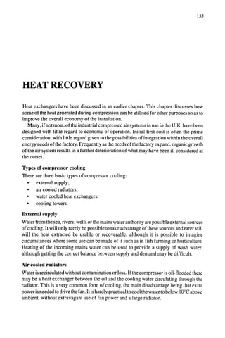
![170 THE PNEUMATIC HANDBOOK
Safety
valve 1 intercoolerAirsi!encer ~] Air intake
Stop "~ / R-li-f ' =' ,__L__ II filter
V I~ ~ ~
alve_ ~ / Pressure wive /~ ~ /
...."~I~----] J Moisture gauges '*'__"~N),
~. .~~.~ I~J~tJ-LI/
Pressure -]~ .-® I ~1separator ~'~ J I~ I -I V
Aeceiver ~ _I /
0 t o r g a u g
e Aftercooler 1 FY
Automatic Automatic Two-stage
drain valve drain valve double-actingaircompressor
[
FIGURE 3 - A typical compressed air installation.
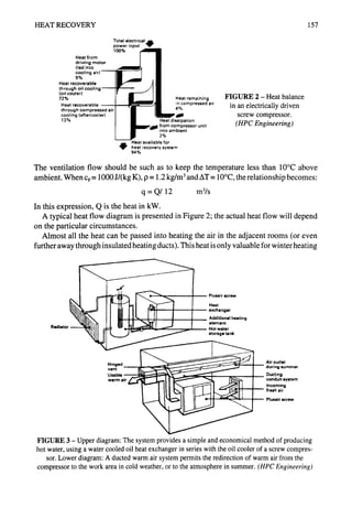
Types of intake filters
Intake filters (Figure 4) commonly used are:
• Paper filters - with renewable elements used on all types of compressors. Filtering
efficiency is high (over 99%) with a typical pressure drop of 2.5 to 3.5 mbar if
correctly sized. They are not recommended for use with reciprocating compressors
Paper Fabric
, %;@
Labyrinth-type
oil-wetted Inertial
FIGURE 4 - Types of intake filters. (AtlasCopco)
Oil bath](https://image.slidesharecdn.com/pneumatichandbook-231106162117-d8c7a9ba/85/Pneumatic-Handbook-pdf-172-320.jpg)


![183
BREATHING AIR FILTRATION
The purity requirements for compressed air used for respiration and hygienically critical
applications such as hospital patient recovery and life support in hazardous environments
such as mines, underwater tanks, etc, must be free of toxic or irritating ingredients, odours
dust and solid particles.
Numerous organisations and agencies around the word have established specifications
pertaining to the purity of compressed air for human respiration. Although variations in
requirements exist, mainly due to the method and type of application, it can be seen from
Table 1 that there is substantial agreement between the various standards.
Country
TABLE 1 - Breathing air specifications in various countries
Specification Maximum content of"
Germany
CO
mff m 3
Oil mist
mg/m3
Australia AS 2299-1979 1 10
France Ministr. Trav. 74725
0.3
DIN 3188
BS 4275
BS 4001 (diving std)
NZSS 2190
0.5
ZI80.1 M85
8
30
5
10
10
U.Ko
U.K.
New Zealand
Netherlands
S. Africa
U.S.A.
Law No 487.21980 0.3 10
10
ANSI Z86.1 1973 5 10
1
0.5
Canada
prEN 12021 see note
European
Note
C02
ml/m3
900
1600
1000
500
500
500
300
500
500
500
500
]Waer
1O0 mg/m3
-51 °C dewpoint
-50°C dewpoint
-43°C dewpoint
60 mg/m3
Pressure dewpoint
5°C below lowest
ambient
as above
EuropeanStandardPrEN12021anditsequivalentBSarenotyetissuedandvaluesmaydifferfromthosequoted.TheCOcontent
isundecided,butis likelytobe5ml/m3(partspermillion- ppm)inU.K.and 15ml/m
3inotherEuropeancountries.
Thereshallbenotoxicorirritatingingredients,odour,dustor~lid particles.](https://image.slidesharecdn.com/pneumatichandbook-231106162117-d8c7a9ba/85/Pneumatic-Handbook-pdf-185-320.jpg)

![I ATMOSPHERICAIR SOURCE I
IPurity monitoring point (1) I
I COMPRESSOR
I
I AFTERCOOLER
I
~ COMPRESSORSYSTEM
CONTROLSANDALARMS
"4-~STANDBY COMPRESSOR I
-4~ AIR RECEIVER I
WATERANDOIL SEPARATOR I
IPurity monitoring point (2) I
IPurity monitoring point (3) I
-~ ALARMDEVICE )
I
BREATHING AIR FILTRATION 185
iPurity monitoring point (4) I
I COALESCING
FILTER(s) [
I °n I
!
II=°::,'A':Z"
I '
I OAS ,,'T,,C.~ I
!
I °ATA'Y, I
!
[ PARTICLEFILTER ]
I
.OT,O. ! .,.,,.o,....sso.. ~,A-,,. I
PIPLqNORK j
I NON-RETURN
VALVE ]
I
I
! °omo. o.,, I
!
I ~"°" I
I BREATHING APPARATUSI
FIGURE 1 - Basic elements of a system to deliver breathable air. (WillpowerBreathingAir)
must be based on the recommendations of the manufacturer of the air line respiratory
protective equipment.
Contaminants
Table 3 shows the major contaminants that can be present in air lines.](https://image.slidesharecdn.com/pneumatichandbook-231106162117-d8c7a9ba/85/Pneumatic-Handbook-pdf-187-320.jpg)


![202 THE PNEUMATIC HANDBOOK
Air dryers
[
1 Vapour removal
Aerosol removal [ ~
" Thermal devices Sorption devices
Mechanical devices
(momentum transfer) (heat transfer) (mass transfer)
i I i
~i 99%(~ 60tol00°FD~P 1 PSA ~- ~ -j~-,-- "~
"-~"
'" --'~ l " -40
E ciency> / ~ l 2"TSA ~~~-'~ -150°FDP
> 30"W.C. /kP I :ii~: 3. Purge strip ! i i
2 ~t1[~It~'~-" I 4"R°tating ! I ~ I
/
1. Shell & tube I~LII[tIE]IFI I drum ! / /
Plate ~ltfl I 5. Cartridge i ~ t
i Packed bed [t'1:1'[~,~
~,~_ / 6. Pouch / ~l I I ,,!
1. Pleated Coalescing filter , l,:i~;~:~~ Heat Solid ~] ( j
2. Wound j , ,~- -r-- exchanger absorbent'-L_~_~ ~"
f
1. Wire mesh
2. Packing
3. Gravel
4. Sand
5. Baffle
Efficiency > 98%
I
~< I"W.C. /kP
Impingement
separator
1
iciencv >90%
3 W.C. AP
1. Cyclone " / Centrifugal
2. Vane ~ separator
~.. _j
35~to55°FDP ~- l~-~'~40t 80°FDP
"~ ~ 1. Deliquescent ] ~i
~1 2. Rotating drumI
, ~ ~ I S. Non- , t
It I deliquescent I ~
n So,0
system absorbent I ~ ~
J
'x
-20 to 55°FDP © 20 to 60°FDP
I
1. Glycol solution
i! 2. Brine solution
3. Acid solution
4• Chelates
: /,~ =.o
Liquid~> ~ ~ 1
absorbent
1
.Pc/ever
J
Chiller
system
Expansion/
evaporation
DP = Dewpoint of effluent.
performance values are typical•
-4
7
Cot'a,n.
~,0to 0°F DP
I ( ,, 20 to 6()°FOF
• ~-
1 Cross flow ~--.-~.~<_-~
2. Counier flow~
Membrane " ~
separation
Regenerative ~.
heat exchanger
FIGURE 2 - Types of air driers for aerosol and vapour removal.](https://image.slidesharecdn.com/pneumatichandbook-231106162117-d8c7a9ba/85/Pneumatic-Handbook-pdf-204-320.jpg)


![AIR DRYERS 211
:i
......~i~!;i~.,
i;iiii~iii!iiii!:i~iii
!i..... !ii!i
::::::::::::::::::::::::
.::~:~
....
" •
....... ~III.S
'~;::~i!:.
~~.
~ii~,~Ai::i!iiii!i!ii',
!~:'
......,]',:~::i,~!i'!~
.....................
...... :~;i!
..... .~'~:;;iiiiiiiiiiP[%i
~!
.......... ::,::::~:~,,:~',~iii~!i
Nii;iii;:: :.....
i
....................................
!iiii!:
.............. ~iii!
Heat regenerated dryer. (ultrafilter)
switch over ensures that the desiccant will not bejolted by the inrushing gas flow. A drying
period of about 3 minutes provides an effluent dewpoint of-40 °C or better. A full three
minutes is used for the drying period. However during the regeneration process, which is
occurring in the offstream chamber simultaneously with drying in the onstream chamber,](https://image.slidesharecdn.com/pneumatichandbook-231106162117-d8c7a9ba/85/Pneumatic-Handbook-pdf-213-320.jpg)


![240 THE PNEUMATIC HANDBOOK
The advantages are:
• Corrosion resistant inside and out. No scale or rust can form, so the loss through
friction remains low and constant.
• Easy to handle. One-eighth of the weight of steel.
• Easy to joint by cold solvent welding. A correctly made joint cannot leak.
• Self-coloured (light blue) for identification. Meets BS 1710 for compressed air
services.
• Non-toxic.
• ABS is available in two pressure ratings NP 10 (up to 10 bar) and NP 12.5 (up to
12.5 bar). The NP 12.5 rating is recommended for airline use.
One limitation on its use is that it softens and loses its strength at increased temperature.
It retains its 12.5 bar rating up to 20°C; it should not be used, without reference to the
manufacturers, above 50°C, at which temperature its pressure rating is reduced to 8 bar.
Installations using ABS must be provided with an aftercooler with a temperature cut-out
to ensure that there is no chance of hot air reaching the plastic. Transient pressures up to
10% over the maximum can be tolerated. In installations where there is some carry-over
of oil from the compressor, the manufacturers of the tubing should be consulted, as there
may be incompatibility between the tube and the oil; synthetic oils should not be used.
Table 2 compares the weight of ABS with alternative steel and copper pipes. Figure 1
shows a selection of fittings used with ABS piping and Figure 2 part of a mains system.
Note that screwed fittings may not be used for direct connection to the pipe; only solvent
welding is permissible.
ABS pipe may be used underground or in overhead installations.
Copper pipe
Copper tubing for air lines should conform to BS 2871 :Part 1. No other earlier standards
should be used. It is almost invariably used with compression fittings to BS 2051: Part 2.
TABLE 2 - Comparison between steel, ABS and copper pipes
ABS (12.5 bar)
Actual o.d
(mm)
16
20
25
32
50
63
75
90
100
Weight
kg/m
0.1
0.13
0.18
0.28
0.69
1.09
1.54
2.23
3.31
Steel to BS 1387
Nominal Light Medium Heavy
bore (in) weight weight weight
(kg/m) (kg/m) (kg/m)
3/8 0.67 0.84 1.02
1]2 0.95 1.21 1.44
3/4 1.38 1.56 1.87
1 1.98 2.41 2.94
1!/2 3.23 3.57 4.38
2 4.08 5.03 6.19
21/2 5.71 6.43 7.93
3 6.72 8.37 10.3
4 9.75 12.2 14.5
Copper to BS 2871
o.d. Weight
(kg/m)
15 0.28
18 0.38
22 0.53
28 0.68
42 1.37
54 1.77
67 2.23
76 3.13
108 4.47](https://image.slidesharecdn.com/pneumatichandbook-231106162117-d8c7a9ba/85/Pneumatic-Handbook-pdf-242-320.jpg)
![PIPE MATERIALS AND FITTINGS 241
FIGURE 1 - ABS air line fittings. (Durapipe - S+LP, Glynwed Pipe Systems)
...................
!;iJ
!~iJJi
]
FIGURE 2 - ABS air line installation. (Durapipe - S+LP, Glynwed Pipe Systems)
Copper piping is not normally used for air mains, but because of its ease with which it
can be manipulated and joined it is common for branch lines. The cost is higher than steam
barrel or ABS. Care should be taken when forming bends; any of the usual bending
techniques are permissible, but a smooth ripple-free inner surface is essential to minimise
pipe friction.
Steel thin-wall pipes
Thin-wall tubes made of stainless steel or carbon steel are also occasionally used.
Compression fittings in stainless steel or brass are used for joining.](https://image.slidesharecdn.com/pneumatichandbook-231106162117-d8c7a9ba/85/Pneumatic-Handbook-pdf-243-320.jpg)
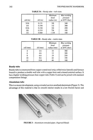


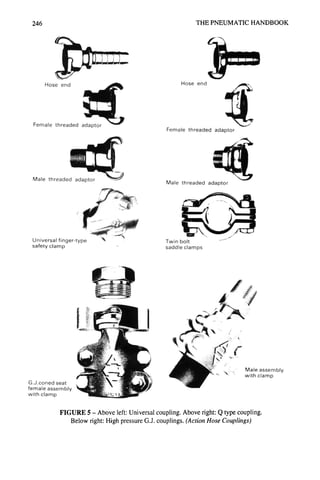
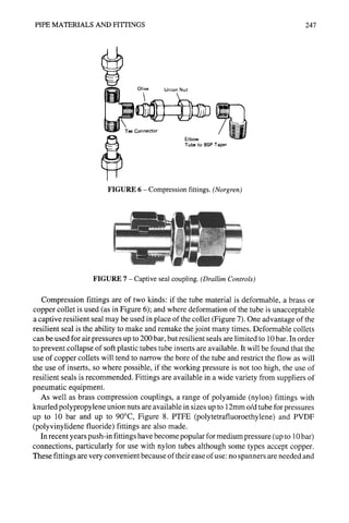

![PIPE MATERIALS AND FITTINGS 249
FIGURE 10 - Push-in tube fittings in a manifold. (Legris)
Method of assembly
1.Select required com-
Brass Collet Tube Tube _a_ , x
r ~ ponent from wide range
collet tooth support stop of push-in fittings.
2.Ensure that end of nylon ¢~-~-~,~.
tube is properly squared
o.
Sii~s!~iy push tube into
until it locates
O-ring. Then pull
4.To dismantle s ~ ~
Lead-in Tube o.d. Nitrile push the tube into the L-v.....f"/~-~-"',,~-'~.
chamfer marked on O-ring fitting, hold down the //%rV (.~A]"~ "~
collet collet and withdraw the,' ~ ~ ~ ~
tube.
FIGURE 11 - Push-in tube fittings with tube support. (Norgren)
Connections can be made and remade under pressure; the ends should be self sealing so
that after disconnection the air cannot leak. Some types incorporate a bleed hole so that
the down stream pressure is vented before disconnection; this eliminates one of the causes
of whipping hoses. Couplings can be single or double cut-off according to whether one or
both ends of the line are needed to be sealed. Most of the quick release couplings have a
swivel action which reduces strain on the connection and thereby increases the life of the
hose. See Figure 12.
They are made from brass, steel or plastic (usually Delrin). Plastic couplings have a
pressure limit of 10 bar. Some of the couplings are supplied with a hose stem with a barbed](https://image.slidesharecdn.com/pneumatichandbook-231106162117-d8c7a9ba/85/Pneumatic-Handbook-pdf-251-320.jpg)


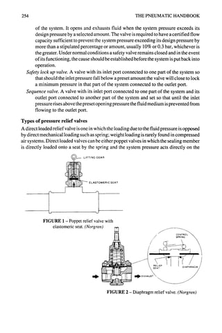
![REGULATING VALVES 255
seating member (Figure 1), or diaphragm valves in which the spring acts against a
diaphragm exposed to the system pressure (Figure 2).
Poppet valves suffer from serious drawbacks. Their performance is inconsistent due to
"stiction", they are insensitive because of the small seat areas and they have a limited flow
capacity. Diaphragm operated valves eliminate some of the drawbacks of the simple
poppet valves: because pressure is sensed over a larger area (that of the diaphragm) they
are more sensitive and have a larger flow capacity. However direct operated diaphragm
valves still have performance limitations, due to the size of the diaphragm in relation to
the spring loading.
Most modern pressure relief valves, at least in the larger sizes, are pilot valves, of which
there are two varieties. A 'pilot controlled relief valve' is a valve in which the loading
spring is replaced by fluid pressure from a control pilot; the pilot pressure comes from a
pressure regulator which is remote from the relief valve and has its own supply which may
be independent of the main supply, see Figure 3. A 'pilot operated relief valve', usually
a diaphragm type, is one in which a small integral spring-operated valve controls the
opening of the main valve; system pressure normally keeps the main valve closed and no
external supply is needed.
Pilot controlled relief valves have superior characteristics to those of direct spring
systems. Pressure is applied to the control side of the diaphragm from a pilot regulator. A
small bleed is necessary to prevent control variations due to temperature fluctuations.
Relief valves controlled by pilot regulators do have shortcomings when used for system
relief, but they are useful when the control has to come from a separate supply or when the
relief pressure needs to be altered from time to time; a pressure gauge can be incorporated
in the pilot line for pressure setting purposes. Unfortunately regulators are not fail-safe and
if one has to incorporate another relief valve in the pilot line, the whole circuit becomes
very complicated.
The integral pilot operated relief valve is now the one most commonly used. This is
really two valves in one body: the relief pressure is set by the spring load on the pilot relief
CONVENTIONALPILOT FEEDBACKPILOT
I• line
PilotRegulator ~i~pply ~ ' s e
/ Pilotoutput ' ~ Pilotoutput
~ ~ l i n e
line
s.upp~y//~~_ suppl
air ~ "~"-,~",,]_ PilotOperated air PilotOperated
- ~ J Regulator Regulator
~ ~ Outlet Outlet
~ air air
Feedback Pilot Regulatorsgive more sensitive control and quicker reaction to downstream pressurechanges.
FIGURE 3 (Norgren)](https://image.slidesharecdn.com/pneumatichandbook-231106162117-d8c7a9ba/85/Pneumatic-Handbook-pdf-257-320.jpg)


![258 THE PNEUMATIC HANDBOOK
W
INCOMING ~ ~ REGULATED
AIR ~_ PRESSURE
-4" OIL-FOG "~
"llltl/~ t 1t //It111111 I]t
, II
i
As compressed air passes through the shut-off valve and enters the filter section (A) it
passes through the directional Iouvres (B) forcing it into a whirling flow pattern. Liquid
particles and heavy solids are thrown against the inside wall of the bowl by centrifugal
force. The liquid then runs to the bottom of the bowl where it is either removed by the
automatic drain assembly or by the manual drain. The baffle (C) maintains a 'quiet zone'
in the lower portion of the bowl to prevent air turbulence from picking up the liquid and
returning it to the air stream. The air then passes through the filter element (D) to remove
solid contaminants. The automatic drain assembly dumps the liquid as it collects. As the
liquid builds up in the bowl the float (E) rises, causing the piston type automatic-drain
assembly (F) to open and release the liquid under pressure. The drain mechanism is
protected by a protective screen (H). From the filter, the compressed air goes to the
regulator section.
When no load is applied to the adjusting spring (J), the regulator valve (K) is closed. Asthe
knob (L) is turned, it applies a load to the spring which is transmitted to the valve through
the flexible diaphragm (M) opening the valve. The air pressure side of the diaphragm is
connected to the regulator outlet by syphon tube (N) so that regulated pressure is exerted
against the diaphragm. As the regulated pressure increases, the pressure against the
diaphragm increases, forcing the diaphragm to compress the adjusting spring until the
load exerted by the spring is equal to the load exerted by the regulated pressure. Excess
downstream pressure is vented through relief seat (0). The pressure setting can be locked
with the snap action lock (P).
As the filtered and regulated air enters the lubricator a portion of it flows through the check
valve (Q) to pressurize the bowl. The major portion of the incoming air flows through the
lubricator past the flow sensor (R) which allows the lubricator to automatically maintain
a constant oil density.
The combination of the pressurized oil reservoir and the pressure differentical created at
the flow sensor causes the oil to flow up the syphon tube (S). The drip rate can be set by
adjusting knob (T) as it flows through the sight-feed dome (U). The setting can be locked
with snap action ring (V).
All oil passing through the sight-feed dome to the orifice (W) is converted to constant
density fog and continues downstream to the point of application.
FIGURE 6 (Norgren)](https://image.slidesharecdn.com/pneumatichandbook-231106162117-d8c7a9ba/85/Pneumatic-Handbook-pdf-260-320.jpg)


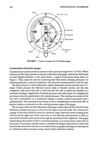


![PRESSURE GAUGES AND INDICATORS 267
measurements down to 25 torr. This range is referred to as low vacuum. For high vacuum
(lower absolute pressure), special vacuum gauges are used.
The mercury manometer can be used down to 1 torr. The McLeod gauge is a special
form of mercury manometer with three limbs, one of which is sealed at the top. Pressure
is determined by measurement of the compression of the gas in the sealed limb. This takes
the range of the mercury manometer down to 10-6.It is intended for laboratory use but more
robust forms have been developed for general use.
Medium vacuum can be measured by thermocouple and Pirani gauges. These operate
by measuring the thermal conductivity of the gas, which is proportional to the number of
molecules present (and thus the pressure). The range is from 10-3to 1 torr.
For very high vacuums, down to 10-1°torr, special thermionic gauges are available and
for extremely high vacuum down to 10~2,mass spectrometer analyser techniques are used.
Gauge pressure
Pressure measuring devices normally measure the difference between applied pressure
and atmospheric pressure and thus indicate gauge pressure (or vacuum pressure in the case
of a vacuum gauge). The equivalent absolute pressure is determined by relating the gauge
pressure to zero pressure as a datum- see Figure 7. In the case of positive pressure above
atmosphere, absolute pressure is the sum of the gauge and the atmospheric pressure
(normally assumed to be 1 bar). Since pneumatics are mainly concerned with gauge
pressure less than 10 bar, the difference between absolute and gauge pressure can be
significant.
Absolute
pressu re
~,
]
Gauge
pressure
Vacuum pressure
Atmospheric pressure
,.////////7/'////'/////
Zero pressure
FIGURE 7](https://image.slidesharecdn.com/pneumatichandbook-231106162117-d8c7a9ba/85/Pneumatic-Handbook-pdf-269-320.jpg)


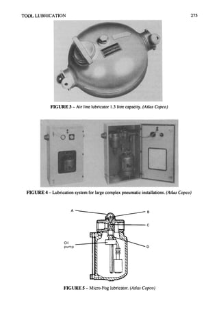


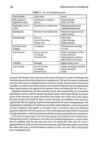


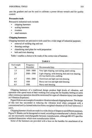


![CONTRACTORS TOOLS 325
Figure 5 shows the forces acting on the piston of a percussive tool. The following
quantities are derived from a consideration of the acceleration of the piston.
Work done on the power (impact) stroke = PAS
Time forpowerstroke = (2MS)%pA
Terminal velocity = (2PAS)'/2M
2MS) I/2
Time for power and return stroke = (1 + k) PA
where k is the ratio of the time spent on the return stroke to the time spent on the
power stroke.
Blow rate =
1 (PA) q2
l + k 2MS
Total work output = Blow rate x work/blow =
PAS (PA)'2
1 + k 2MS
(PA)3'2 (MS-~-)'/2
l+k
These equation are applicable when all units are consistent. In terms of the standard
engineering units which have been used throughout, ie stroke in metre, area in (metre)2,
pressure in bar and mass in kg they become:
Work done on power stroke = 1@ PAS joule
MS ~'/2
Time for power stroke = 0.00447 ~] s
Terminal velocity = 447.0
PAS) '/2
M
m/s
Time for power and return stroke = 0.00447 (1 + k) (M~-~) '/2
Blow rate -
224 ( PA ~'/2
1 + k ~] per s
Total work output = 22.4 x 10³ X
(PA)3/2
l+k
kw](https://image.slidesharecdn.com/pneumatichandbook-231106162117-d8c7a9ba/85/Pneumatic-Handbook-pdf-326-320.jpg)
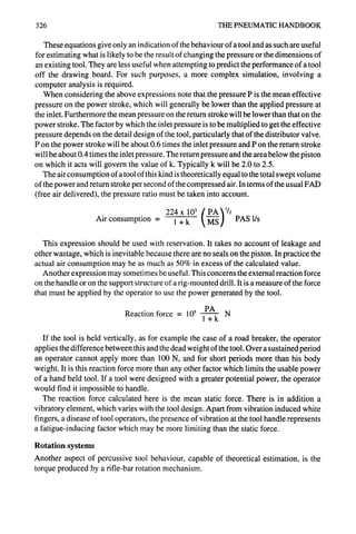
![CONTRACTORS TOOLS 327
The function of this method of rotation should be understood first. The modem rock drill
derives its action from the traditional method of hand drilling with hammer and chisel. The
old time miners used to drill in teams: two men would wield hammers, and a third would
hold the chisel and rotate it. The rock was broken by chisel action rather than by rotary
cutting, and so it is in a modern rock drill; only in relatively soft rock such as coal and shale
is it possible to drill by rotary action. It is easier to rotate a drill by hand in an anti-clockwise
direction, so that is the direction that a drill turns. Smaller drills that can be used for both
rotary and impact drilling are also fitted with clockwise rotation; and the heavier rock
drills, using coupled rods that have to be screwed together, include a facility for reversing
the direction ofrotation to allow for uncoupling of the rods. Some stoper drills, which serve
the dual purpose of drilling and acting as torque wrench for roof bolting, are also equipped
with a clockwise rotation mechanism.
A rock drill must be forced against the rock by a feed force having the magnitude given
in the equation above. The applied force should be just sufficient to keep the bit in contact
with the rock, but no more. As the bit rebounds after the rock is broken, there is no
resistance to rotation, and so a comparatively small torque is needed just to index the bit
to the next cutting position. Air or water removes the chippings so that the chisel action
is not cushioned by drilling detritus.
It is for this reason that the rotation occurs on the return stroke of the piston. The angle
of the splines on the rifling is just sufficient to index the bit by about 20 to 30 degrees per
blow, so that while the blow frequency may be of the order of 2000 per minute, the
rotational speed will be about 100 per minute. It is usual in English usage to refer to a drill
having a rotation (for example) of 1 in 30, as meaning that the bit rotates by one complete
turn for every 30 inches of travel of the piston - a lead of 30 inches. Common values of
lead are 30, 35, and 40. In SI units, the lead can be expressed in mm.
The shallowness of the angle of the rifle-bar, used to achieve such a slow rotation, means
that friction between the splines and the rifle nut and between the chuck and the piston
absorbs a high proportion of the available energy on the return stroke. It is important that
the sliding parts are well lubricated to minimise the coefficient of friction and to prevent
a common cause of wear- the break-up of the splined surfaces.
An advantage of this form of rotation is the absence of any appreciable reaction torque
to be sustained by the operator.
Estimation of the torque provided by rifle bar rotation
Refer to Figure 3. The relationship between rotational torque and force on the piston is as
follows:
T (r- larl:dl)did2
F 2 (gr [d, + d2] + ~:d~d2- g2nd~)
where T = the torque available for rotation of the bit
F = the force applied by the air pressure to the piston on the return stroke
d~ = mean diameter of the rifled splines](https://image.slidesharecdn.com/pneumatichandbook-231106162117-d8c7a9ba/85/Pneumatic-Handbook-pdf-328-320.jpg)


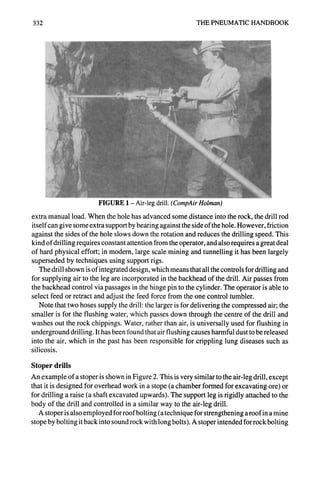


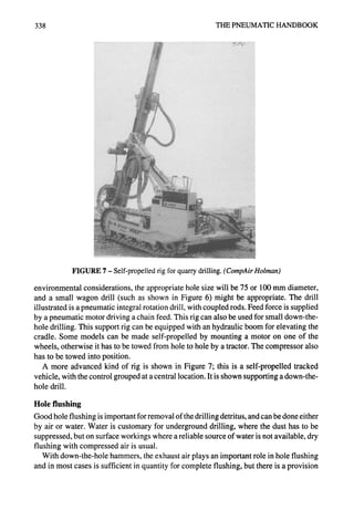


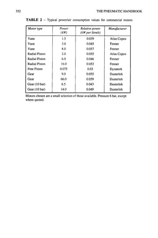


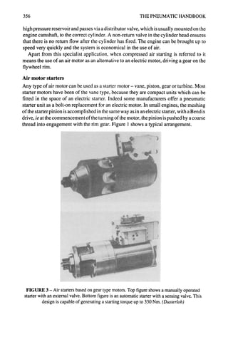
![APPLICATIONS FOR AIR MOTORS 357
One disadvantage of the vane motor is that its starting torque is less than its slow-speed
running torque, but starting a diesel engine requires maximum torque at its breakaway
point. Both gear and piston motors have better starting torque characteristics than a vane
motor, and theoretically are more suited to this application.
Air starters have an advantage over electric starters in that the motor can be rotated
slowly by admitting air through a small pilot bleed until the gears can mesh. Instead of a
Bendix drive, the meshing can be accomplished by an air piston and the disengagement
by a spring. The operation can be manually controlled, in which case before the full air
supply is admitted to the motor, a visual (or audible) check is needed to confirm
engagement of the starter gear. Alternatively for standby sets, where it is required that an
engine should start without manual intervention, it can be automatically controlled by
means of a sensing valve which ensures that the main air valve does not open until there
is complete meshing engagement of the pinion.
Air supply for a starter is typically taken from a reservoir charged by the air brake system
on a vehicle or by a separate compressor for shipboard installations. For emergency use,
the reservoir can be refilled from a high pressure gas bottle.
--3 2
/1 T
-J
4 6 8
1.Motor housing
2.Vane
3.Rotor
4.Air inlet
5.Air exhaust
6.Gears
7.Gear box housing
8.Starter pinion
FIGURE 4 - Air starter with vane-type motor drive.
4 3 2
_1
_
] ~
TO be
~ad to IL suitable
point on sides or base
Connection for
electric cables
1.Pneumatic starter
2.Differential pressure oiler
3.Dirt trap (only required
with dirty air
conditions)
4.Pressure-reducing valve
with built-in safety
valve
1
z ,-/z -.- ~'~
FIGURE 5 - Remote-controlled air starter, saddle-mounted and ancillary parts in the
main air supply line.](https://image.slidesharecdn.com/pneumatichandbook-231106162117-d8c7a9ba/85/Pneumatic-Handbook-pdf-358-320.jpg)


![362 THE PNEUMATIC HANDBOOK
TABLE 2- Approved bodies for pneumatic noise testing
Organisation
A V Technology
Avtech House
Cheadle Heath
Stockport SK3 OXU
Taywood Engineering
345 Ruislip Road
Southall UB1 2QX
Type Examinationfor
Roadbreakers Compressors
× X
X X
imported into another without further inspection. In the U.K., the authority is the
Department of Trade and Industry. The laboratories which are able to perform the tests are
commercial bodies (rather than Government Laboratories, as in some countries of the
Community) and are inspected by NAMAS (National Measurement Accreditation Serv-
ice). At the present time only the bodies listed in Table 2 are approved to perform tests.
They are in commercial competition, so the charge for performing the tests will vary.
It should be understood that the noise level measured according to the Directive is not
necessarily typical of the actual noise that is likely to be experienced by an operator of a
tool or by a passer-by. The test is performed for type approval of the breaker alone, and
so it is devised in such a way that the steel ring and the radiated noise from the concrete
block are suppressed. The quoted value is the sound power level emitted by the breaker,
in the rather artificial test arrangement shown in Figure 2. In order to assess the actual noise
exposure in practice, sound pressure measurements should be taken. The type approval
test is useful in comparing one breaker with another, but should not be used to determine
the noise environment on a particular site.
SILENCED COMPRESSOR SITUATEDSO THAT
NOISE DOES NOT INT=J::~FEREWITH TEST THREE STABILIZINGTIES
I1 AIR RECEIVER WITH I-I ~,
~ J " PRESSURECONTROLLEDTO 6 BARI I " ~,~C
[] ~_,~-lOm FROM TEST MACHINE
20m LENGTHOF HOSE THREE CYUNDERSTO GIVE
PRESCRIBED DOWN FORCE
._e-------- - - i-~--- ------- - _
~ _ _ ~ "
FIGURE 2 - Test arrangement to measure sound power from road breakers
according to EEC Test Code. (CompAirHo/man)](https://image.slidesharecdn.com/pneumatichandbook-231106162117-d8c7a9ba/85/Pneumatic-Handbook-pdf-363-320.jpg)


![NOISE FROM PNEUMATIC EQUIPMENT 365
E
v
E
z
0
iii
_J
111
10000--
100
10
0.1
2
Z 1
lP
I t t
!
-- 0
w,w,
1 10
1 , , . ..=.l • , i , ==**i = , . , ,=**
lO0 lOO0 10000
FREQUENCY, Hz
FIGURE 3 - Third-octave hand-arm vibration exposure limits defined in the ISO Standard
5349. The five curves correspond to the five multiplying factors given in Table 4.
Superimposed is the vibration level of a typical road breaker. Note the maximum response
at the tool operating frequency.
TABLE 4- Multiplying factors for various exposure durations
(as given in the International Standards Organisations Standard 5349)
Exposure time
during 8 hour
daily shift
Up to 30 min
30 min to 1 hour
1 hour to 2 hour
2 hour to 4 hour
4 hour to 8 hour
.....
Not regularly
interrupted
< 10 mirdhr
5
4
3
2
1
Multiplying factors for various minutes of
interruption in vibration exposure per hour
..
!0 to 20
Regularly interrupted
20 to 30
...
] 30 to 40
w
5
4
3
. . . . . . . . . . . . . .
[ ,> 40 min/hr
m
5
5
4
.....
vibration depends on the amount of exposure during a working day and on the frequency
of rest periods. Any recommendations must be provisional in the light of present
knowledge on the subject, but most authorities accept the general validity of the data. The
standard gives much useful information on the precautions which should be taken to
prevent vibration injuries.](https://image.slidesharecdn.com/pneumatichandbook-231106162117-d8c7a9ba/85/Pneumatic-Handbook-pdf-366-320.jpg)


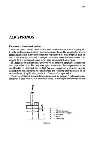
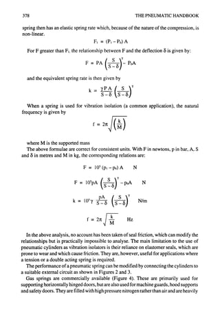


![AIR SPRINGS 381
AIR
SPRING
+
AIR
SPRING
AIR
SPRING
(T) REGULATORS
SUPPLY
© i
AIR ..... CHECK
SPRING VALVES
AIR AIR
SPRINGS SPRINGS
Q'~ SUPPLY
..... CHECK
AIR VALVES
AIR
SPRINGS SPRINGS
LEVELING
VALVE
AIR ~[~ AIR
SPRING SPRING
AIR AIR
SPRING SPRING
AIR AIR
SPRING SPRING :......
~ N ~ LEVELING
VALVE
G SPRING ]
eLEVELING
VALVE
TOAIR
SUPPLY
CHECK
VALVE
FIGURE 9 - Typical circuits for air supply to an air spring isolator.
Note that in each case thereis only a three point control.
reservoir is provided as in Figure 3. They eliminate problems like fatigue and permanent
set found in other isolators. The height of air spring isolators can be accurately controlled
by regulating the air pressure. With a simple feedback device, such as a levelling valve,
the height can be accurately controlled to + 1cm; with precision controllers, the height can
be maintained to + 0.25 mm. The air supply circuit needs careful consideration. If the air
is sealed in the bellows with an inflation valve, there will be some leakage through
permeation over a period of time (a loss of 2 bar a year is typical), so the pressure needs
to be regularly checked. Otherwise a live pressure supply must be provided either to each
spring individually or to groups of springs, as shown in Figure 9. The principle to follow
is that there should be only three points of control on each structure.
Design Techniques when Using Bellows
Bellows are available in a wide range of sizes and configurations. Maximum diameters
vary between 150 mm and 700 ram, in the styles shown in Figures 5 to 8. Up to three
convolutions are available as a single unit which can be extended by bolting several units
together in series with an intermediate steel plate. Suppliers of these units provide curves
which enable the static volume/height and the force/pressure relationships to be deter-
mined for each style. When designing an actuator system, it is better to rely on these curves
than to attempt to work from basic principles.
When used as an isolator, the static curves can be used as the primary information from
which to calculate the dynamic spring rate. As in the case of the cylinder discussed above,
isentropic compression can be assumed (i.e. the use of an index of compression = 1.4),
although a value = 1.38 is recommended by one major manufacturer; the difference is
likely to be small.](https://image.slidesharecdn.com/pneumatichandbook-231106162117-d8c7a9ba/85/Pneumatic-Handbook-pdf-382-320.jpg)
![382 THE PNEUMATIC HANDBOOK
TABLE 1 - Air bellows - typical application. (Firestone)
GATE VALVE OPERATOR
E,
WEBB TENSIONING DEVICE
Wind-up
ro,, a,
// ~ ~ Airstr°ke/j~X
KNIFE SPRING ACTUATOR
PAPER SIZING PRESS
••////////////////,
Pivot~..J %~ _JJ~; _]. ,
/////////////////, ~"//,
Airlines
".~f///////////////////
• .~,~;,i,).7/~.~5,,,i,~;,~/;,
"
Frame
QUICK LOCK DEVICE
Latch "'e
bar !
t
GLUING PRESS
Spring Twoconvolution
return airstrokeactuators
, I
!
DIE STRIPPER
i~ ~1
'
~jl.J To,~ie JU
QUENCH TANK ACTUATOR
Guide rail Water level
Qui
PICKLING TANK ACTUATOR
Airstroke -~ ~ ~ Airstrokej~'
Acidtank-~ (~ ~-~- Acid
Wire coils
PRESSURE ROLL FOR CALENDER
Pressu ";
Air=,oke___1~~ ~ I /
Adjustable stops-~::~~~ J L
Support
stand --~ " ~](https://image.slidesharecdn.com/pneumatichandbook-231106162117-d8c7a9ba/85/Pneumatic-Handbook-pdf-383-320.jpg)
![AIR SPRINGS 383
TABLE 2 - Air bellows used as isolators. (Firestone)
DELICATE EQUIPMENT
Delicateequipment
t ~ Patient
-.,,~_.,,~ --.-_-:_- ................. ~
L, ..I
~ Airmount isolators J
CONCRETE FENCE POST/
BLOCK MAKING MACHINE
W
....... ,,,,,,,
||;;;;;;,;; ;;
~'~ ~'~o~]eteinertiabase
Concretefoundation
VIBRATORY SAND PACKER GEOPHYSICAL HYDRAULIC VIBRATOR
[Flask !~ I Flask 1 Truckframe ~Shaker~i ~ ]
o o o ' ~ o i '
~, Airstroke~' Ground
actuators
ELECTROMAGNETIC EXCITER DIESEL ENGINE/GENERATOR SET
i -,.... "~;",]
f!
Electro-magnetic
exciter
Genera
Reboun~l
and ~ Rebound
and
jouncebumpersIMIA jounce
bumpers.
Airmounts
COMPRESSOR ISOLATOR
Compressor
Guide
Airmount LID..
I1"1
: .
• ,!
Floor Stop'i
ViewAA ,j
HYDRAULIC POWER UNIT
A](https://image.slidesharecdn.com/pneumatichandbook-231106162117-d8c7a9ba/85/Pneumatic-Handbook-pdf-384-320.jpg)
![384 THE PNEUMATIC HANDBOOK
FIGURE 10
In a similar way to a cylinder, the forces can be calculated, but account has to be taken
of the variation in the effective area, as shown in Figure 10.
F = (P~-P0) A
(v,t'
F = PA ~ -PoA
FI is the initial force;
V1 is the initial volume at a pressure of P~;
V is the volume and A the effective area at the pressure P.
The volumes and areas are obtained from the static curves.
In order to calculate the dynamic spring rate (where this value is not given in the
published data), a first force at a height slightly above and a second force at a height slightly
below the working height are calculated (a total height difference of 25 mm can be used);
the spring rate is then calculated as the force difference divided by the height difference.
Using this technique, the spring rate is given by a relationship of the form:
V v V v 1
k={P [A2(-~2)-A' (-~-I)]-P°(A2-A"}"~
L is the height difference (25 mm, if that is the height difference chosen), and in this
instance the suffixes 1 and 2 refer to values respectively above and below the working
height.
The natural frequency can be calculated as before, using the calculated stiffness value.
The relationship between the forcing frequency and the natural frequency should be
chosen to give the required degree of isolation, as determined from Figure 11.
General consideration in the use of air springs as isolators
It is recommended that, when using the air spring as a vibration isolator, the ratio of the
forced frequency to the natural frequency should be about 3:1. This will give an isolation
of about 90% (see Figure 11).
As the system is inherently soft, precautions must be taken to ensure stability. The ideal
arrangement is to locate the springs in the same horizontal plane as the centre of gravity.
Where this is not possible, the guideline to be used is: the narrowest distance between the
mounting points should be at least twice the height of the centre of gravity above the plane
of the springs.](https://image.slidesharecdn.com/pneumatichandbook-231106162117-d8c7a9ba/85/Pneumatic-Handbook-pdf-385-320.jpg)


![PNEUMATIC CONVEYING 395
air supply Pil
discharge pq
air-water discharge
to,
$
lift
air-water mix------I-l-ld~l S I L
air injector
water inlet
FIGURE 8 - Air lift pump.
(Atlas Copco)
In Figure 8, the distance H is known as the pumping lift and S is the submergence.
L=H+S
The percentage submergence is defined as
S% = 100 S/L
For low lifts (to about 10 m), a percentage submergence of 80% is possible, but for
higher lifts (up to about 30 m), a percentage submergence of 30% is the limit. In order to
assess the quantity of air required, an empirical formula, developed from a number of tests
can be used"
H
q = C iog~0 [(S + 10) / 10]
q is the ratio of (volume of free air)/(volume of water) and heights are in metres.
C is an empirical constant given in Table 2
TABLE 2 - Values of constant C
Lift H (m)
10 to 20
20 to 60
60 to 150
150 to 200
200 to 250
Constant C
390
370
342
290
247](https://image.slidesharecdn.com/pneumatichandbook-231106162117-d8c7a9ba/85/Pneumatic-Handbook-pdf-396-320.jpg)


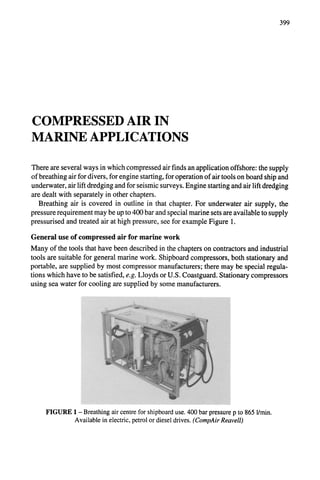

![COMPRESSED AIR IN MARINE APPLICATIONS 401
TRAVELLING BLOCK
|l ,i
_ ii
t~ / ~ ,I
,II
II I
J
CONTROL CONSOLE
1 t ".-d
' "5!} .oo~
POWER AIR ]
PRESSURE VESSELS I
6._.1
._1
AIR COMPRESSOR
FIGURE 3 - Drill string compensator for offshore oil rigs.
CHAIN
sator shown in Figure 3 comprises two compression-loaded hydraulic-pneumatic cylin-
ders. The cylinders are supplied with high pressure air which, in the application illustrated,
is 163 bar. As the rig heaves upwards, the compensator cylinders retract and the hook
moves downwards to maintain the selected drilling load. Thus while the drill platform and
compensator move, the hook remains fixed relative to the Earth. Use of these compensa-
tors ensures that drilling can proceed in high heave conditions.
Use of pneumatic tools underwater
In modest depths of water, down to about 10 m, the standard air tool can be used without
any difficulty apart from the worsened visibility caused by the exhausting air. The back
pressure caused by the head of water acting on the exhaust port causes a progressive drop
in performance; this is particularly true of percussive tools, which become completely
ineffective at a depth of 30 m. From tests performed on a medium size percussive drill,
operating at 6 bar, Table 1 has been prepared.
TABLE 1 - Performance of rock drill under back pressure
Depth
(m)
0
7.5
15
30
60
Gaugepressure
(bar)
0
0.8
1.5
3.1
6.2
Performance ratio
(1) ] (2)
1.0 1.0
0.59 0.75
0.22 0.44
0.0 0.20
- 0.0
Note:Theperformanceratioistheproportionoftheoutputenergyofthetoolavailable
at depth.](https://image.slidesharecdn.com/pneumatichandbook-231106162117-d8c7a9ba/85/Pneumatic-Handbook-pdf-402-320.jpg)


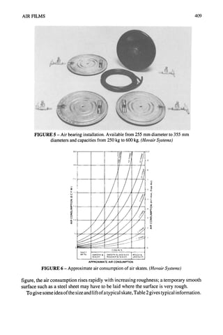


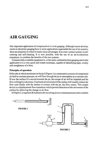


![AIR GAUGING 419
FIGURE 7 - System using flow indicator.
Work Piece Clearline PressureSensitive Pressure
t Unit Gauge Regulator
,, ~ i
i/
Zero C/ontrol Magnitication Pr~esure
Control Monitor
Air
Ilsupplv
FIGURE 8 - System using a pressure gauge. (MercerBrown & Sharpe)
B,,ndBore ii]
Rough Finish Narrow Land
iJiiiiiljQiJiJjJjJjJjJiJjJ!Jii
FIGURE 9 - Mechanical contact air gauging. The air plug has tungsten
carbide pads mounted on reed springs. (MercerBrown & Sharpe)
For mechanical contact air gauging, the air plug of Figure 9 can be used. This has pads
which contact the measured surface and allows the air to pass through the gap made by the
displaced pad.](https://image.slidesharecdn.com/pneumatichandbook-231106162117-d8c7a9ba/85/Pneumatic-Handbook-pdf-420-320.jpg)


![423
CONTROL VALVES
Types of valves
Pneumatic valves can be divided into three main categories defined by the function they
perform: directional control, flow control and pressure control. They can be further
divided into those valves which control the airflow to carry out a power function and those
which perform a control function. The latter includes a number of specialised valve types
which only perform a logic function in control circuits.
They can be also be classified by the method of construction - seated valves, sliding
spool valves and variable orifice valves.
Directional control valves
Directional control valves are categorised by the number of port openings or ways; a two-
port (two-way) valve either opens or closes a flow path in a single line; a three-port (three-
way) valve either opens or closes alternative flow paths between one or other of two ports
or a third port. Other basic configurations are four-port or five-port.
Such valves can also be described by the number ofpositions provided and also whether
the outlet is open or closed in the non-operated position, ie normally open or normally
closed respectively. Description may be simplified by giving number of ports and
positions as figures separated by a stroke eg a 4/2 valve is a four-port, two-position valve.
Figure 1, for example, shows a three-way, two-position directional control valve in a
simple diagrammatic form.
The three-way two-position valve is thus a logical choice for a single acting cylinder
P ~ A
E×
normally closed
P ~ :~ A
t - ]
II
Ex.
normally open
FIGURE 1](https://image.slidesharecdn.com/pneumatichandbook-231106162117-d8c7a9ba/85/Pneumatic-Handbook-pdf-424-320.jpg)


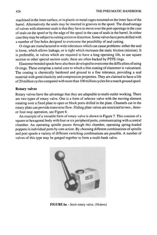


![CONTROL VALVES 431
With sub-base or manifold mounting the valve body has no tapped connections. All
internal ports are brought to the base of the valve and connection is completed by mounting
on a matching sub-base or manifold, carrying corresponding ports. Joints are sealed with
gaskets or O-rings.
Shuttle valves
The shuttle valve is an automatic type of control valve with three-way two-position
characteristics. This is based on a simple three-port body with a moving element in the
form of a free spool, a shuttle or a ball (Figure 12).
],," / " .,..
~-jj
FIGURE 12a- Shuttle valve
with ball element.
4
3
FIGURE 12b- Shuttle valve (4)
allowing ports 1or 2 to be connected
to port 3.
A shuttle valve gives an outlet from either one or two pressurised inlets (whichever has
the greater pressure): the higher pressure inlet moves the shuttle to a position where it
blocks the other inlet. It is thus more of a special valve than a true directional control valve
and its main use is for logic OR switching.
Non-return valves
These allow the flow of air in one direction only, the other direction through the valve
being blocked at all times to the airflow. The valves are usually designed so that the check
is pressurised by the downstream pressure and a spring loaded ball or cone.
The simplest type of non-return valve is the check valve, which completely blocks
airflow in one direction and allows flow in the opposite direction, with minimum pressure
drop across the valve.
As soon as the inlet pressure in the free flow direction overcomes the internal spring
force, the check which can be either a ball or poppet is lifted clear of the valve seat.
Alternatively the check may be lifted off the valve seat by some means, as in the case of
a quick connect coupling.](https://image.slidesharecdn.com/pneumatichandbook-231106162117-d8c7a9ba/85/Pneumatic-Handbook-pdf-432-320.jpg)

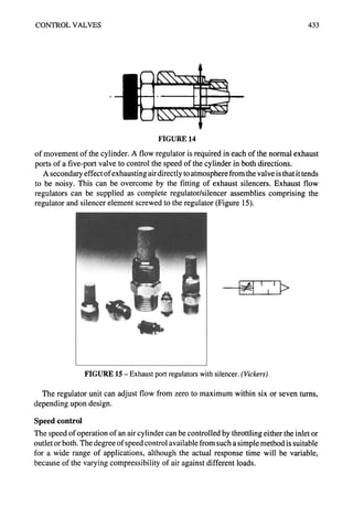


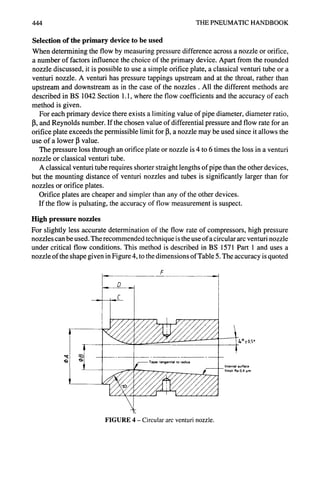

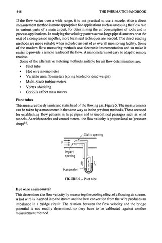


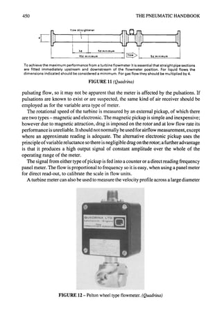


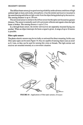


![VALVE CONSTRUCTION 467
• Electrically by a solenoid or electric motor
° By fluid pressure (air or hydraulic operation)
° By self actuation
Standard methods of designating these in a circuit diagram are shown in Figure 4. See
also the chapter on Graphical Symbols.
MANUAL MECHANICAL ELECTRICAL
generalsymbol c~ plunger
• L,
(.I"-'~'--L__pushbutton ~ spring
[~~ solenoid (1 winding)
r'--
~jr ~]__ solenoid (2 windings, opposed)
lever ~ roller
/ L__ I__
/~:~-- pedal
f r---
I// i solenoid(2 windings,progressive)
I I._=._
<•3• uni<lirecti°nal ( ~ ~ electricmotor
roller
FIGURE 4 - Standard symbols for valve control methods.
Manual and mechanical operation are basically similar in that a mechanical force is
applied directly to the moving element. With a lever, the mechanical advantage can be
adjusted to allow for the available force or displacement. It may be necessary to
incorporate a spring detent to hold the moving element in a particular position (either of
the selected positions or neutral). It may also be necessary to incorporate a spring return
so that the valve is held in the selected position only so long as the actuating force is
applied.
Manual and mechanical operation
These valves may have direct or indirect operation of the spool or poppet. In the case of
direct operation, the spool is actuated by a mechanism or by human actuation (hand or
pedal).
Indirectly operated valves are where the spool is moved by the application or removal
of an air supply on the end of a valve spool or on a pilot piston. The thrust exerted by the
air pressure acting over the surface area of the pilot piston overcomes the friction of the
valve and any return spring that may be fitted and causes the spool to move. Valves can
be either dead movement or spring return.
Pedal valves are foot operated, suitable for such purposes as operating machinery or
Safety guards. They can be operated by a cam mechanism that prevents over-travel of the
spool. A compact unit with a small movement gives less operator fatigue during repeated
operations.
Two handed control units are intended to operate a pressure operated spring return valve](https://image.slidesharecdn.com/pneumatichandbook-231106162117-d8c7a9ba/85/Pneumatic-Handbook-pdf-468-320.jpg)


![478 THE PNEUMATIC HANDBOOK
FIGURE 2 - Short stroke,
spring return membrane
cylinder.
Force at 6 bar = 500 N.
(Kuhnke)
bolted together as in Figures 1 and 2. The diaphragm is made of neoprene or fabric-
reinforced nitrile rubber.
The cross-section of the these diaphragm thrusters may be round or assume any other
convenient shape for special purpose clamping as illustrated in Figure 3.
iiii
!ii!!i!iiiiiiiiili{!i!i
!iiiiiiiii
ilfii
ili~!iiiiiiii
fiiiiiiiiiiiil
!!iiiiiiiiiii
il
iii
iiiiiiii{iiiiii
~ii~i~iiii
~!iii~!i!®ii!!!i!!i
iiiifiiiiiiii
iiiil!iiiii!ii
fiiiiiiiiiiii
iii!iiiiii!ii
iiiiiiili!!~i!
~iiii!i!i!i!!!!!!iiii
#i
iiiiiiiiiii
iif
iiiiif!ii
ii!
iii!
!i!i!ii
iiiiiiii
!!iii~!i!i!i!!!!
iii!Imiii
iii
!i!ii#iiii!ii!iiii!iiiiiiiiii~!i
iii!!i!!!i!mi!~i!i!i!i!iiiii!i!i!i!i!i!!!ii
ii!i!ii!i!miiii!iiiiiiiiiili!i!mil
iiiiiiiiil
i!!iiii!
i!Jiiiii!ii
iii~iiiiiiii!i
iii!iiiiiii!!iiiiii!i
~iiiiii
iii
ii~ii
i~!i
!i#iii!ii
~i!i!iiiii
!i~
iiliii
iii
iiiiiif
i!~il!
~iiiii~
~i~!i
ii!ifliiiiiiiiiiiiii#iiiiiiii!#iiiiiii
~
iii~iiilii~!#iiii
iii
~iiiii!
iii
iii
ili!!~i
i~i
iiiii!
iiiiii~i!i
iiiii!
iii
i!iiiii!iiii
iiiiiiiiii
!ii!!~!ii
iii
iiiiiiiiiiiiiii
iii!iiiii
~i!iii!i!
iii!i!iiiiiiiiii
~!iii®ii~iiii~
iiiiiii~iii~!i
iiiii!iiiiiiii
~ii!iil
!~~iiiiiiiiiiiiii
~iJi!~i
ii~
~ii~
~!~i~
fiii!
~iiii
~.~
i~i~"~ ................~]iiii~iii~i~i{if%i~ii!~iiiiiiiiiiiii~ii~iiiii~iii~i~i#iiiifi~#~i~iii~iiiii!iiiiiiiiiiiiiiiiiIiiii~ii~iiii~iii~i~ii~iifiii!i!i#i!fi~iI~ii~ii~fiiiiii!i!i~ii~iiii~ii~#i ............
•"ii~%;:!i~;~!~::~{
~{:]i.,':~'................."...............
~iii~i~i~:iii`~i~i~i~i~!~i~i~i~iiiiii~i!i~:ii~i~iiii~iiiiii`~i~:~:~i~
i~i~ii;;::iii~i':
[-"~-.-":~]!ii'..'."4~i
~ i~iii~{i~i::i~1{
;~{!iii!~!~i.."..'~
~i~~i~iii{i~Ii::i::i!iii~i~li!iiiiii~
!4/i~"
.....................................................................................................................................................................
:................................ ~`~Jii~i~iiii~iii!i~iiiii~i~iii~iiiiii~i~i!iiiii!i!i!i~fii~ii!iiiiiiiii!i~ii~ii~#~ii!iifiiii~i~iiiiiiii!i~i~ii!iiiiiii!i~iiii~fiiiiiii!!iiiiifiiiiiiii~!i~iii{~iiii!~i~#
Exampleof application:
)
FIGURE 3- Selection of diaphragm thrusters. (Festo)
Rodless cylinders
For long strokes, the conventional rod-type cylinder has severe space limitations: it has an
overall length when extended of twice the stroke plus the length of the end caps; the
cylinder rod when extended can flex, resulting in excess wear on the seals and beatings.](https://image.slidesharecdn.com/pneumatichandbook-231106162117-d8c7a9ba/85/Pneumatic-Handbook-pdf-478-320.jpg)


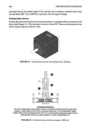


![490 THE PNEUMATIC HANDBOOK
•
ii!ii!i!iiiiii:i~
Ei~i!~!,!ii~iii~i!ili~!ili~i~i~i~i
~i
~iiiii!iiZ!i!iiiii~iiiilili!i~i~i~i!i!~i
.!~i~@ii~i!i!~i~i~i~!~!i!~i~i!i~i~i~i!@i!ii~i~i:i.i~iiiiiii~i!i!i!iii!ii~iiii~iii~i~i!i!i~i~!ii~i~i~i:iii!iii!i!~iiii!iiii~i
......... ..~.~iii!i!iii~iii~i!i!i!iii!ii~iii~iiiiiii~i~i~i~iii!i~i~iiiiiiii!i!
::~:
.........
:.........~:%Z~
............. ...:::.~:~:~,~,~
~
~,::~
::i
iiii{!
q!i!!!iJ::!ii~','?~
~i~:ii::~:ii:i!:::ii:'$i::
:i~i!iil;::::i:ii~:!<
iii:iliJ~
'~
'~?~'Si~i,,',?,i',i',~',i:ii:iii:ii<"iiii
H!iiiiiii~iiiiiiiii~?,:@i::i~i~iiiiiiiiiiiiii!~!!iiiiili:i,
:!i!iiii!iii~i:i!~iiiiiiii!i!}i::~,i~,i'~ii~,i~ili~iiiii!i~ii
!ii, iiiii:i!i!i:i%i
!'ii!!:!:!i!
i:iiiiii?!i!
!:i
iii:!i(i
:ii:i!iii:i!!i!ii:ii
!i!i!iiiiiii!i!i! ii!i:iiii!i!i ii!i
FIGURE 1 - Single-acting (spring return) cylinder. (AscoJoucomatic)
.............................................................................................................
~.....................................................................
.<....................................................................
~..........................
~::::.::~:~:::.:::.
..........................
~.:.~:~:~
............................
~:~:~:~.~:::~
.................~:::::~:~:~:~:~:i
................:::::::::::::::::::::::::......................
~:~:~,~:~:~:~:~i~-~.-..:~:~:~:::~:~:~:~:i:~.-..%~:;:~:~:
iiiiiiiiiiii®i~iiiii®iiiiiiii®iiiii®iiii~i®i~i~ii~ii~!iii~ii#®iiiiiiiiiii®iiii~iii~ii®iiiiiiiii~iiiiiiiiiii~ii~iii~i~iiiii~]~]~;I@~e~
........ ~ii li
ii®i~ii~{iii®iiiii®~i#iii~ii~®ii~iiiiii!#®!ii~i~ii~i®ii~ii~i~i®i~®®iii~I~i@~
l~:i~'
....... ~ii
FIGURE 2- Double-acting cylinder. (AscoJoucomatic)
FIGURE 3 - Heavy duty cylinder with tie rods to ISO standards. Pressures up to 16 bar.
(Norgren)
...~!
•
..i.: :!'~::i':ii~
~ir!..
. . ,
...
FIGURE 4 - Light duty cylinders to ISO 6431. Cylinder body in aluminium alloy, piston rod
in stainless steel, die cast aluminium end caps. End caps attached by steel screws. (Norgren)](https://image.slidesharecdn.com/pneumatichandbook-231106162117-d8c7a9ba/85/Pneumatic-Handbook-pdf-490-320.jpg)


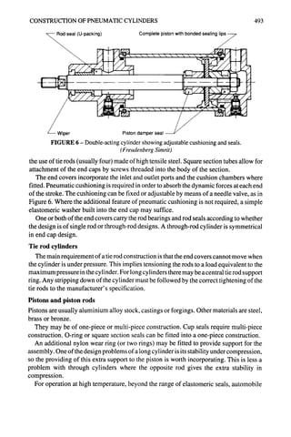

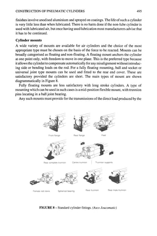


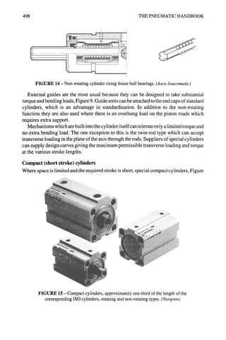


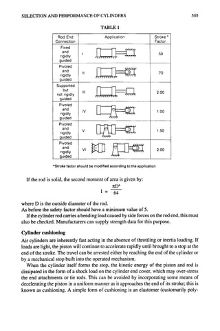


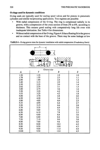
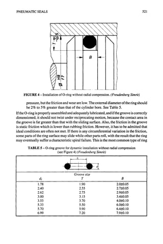


![524 THE PNEUMATIC HANDBOOK
I
i i
V
HYDRAULICS
x
v
l
i I
i I
PNEUMATICS
x
v
FIGURE 7- Differing lip geometry and contact pressure profile with
hydraulics and pneumatics. (FreudenbergSimrit)
U-rings have to be fitted into the piston. The seals are often separated by a beating ring
which has little sealing function in itself but helps to take side loads. A piston containing
these elements can be long, which is undesirable in compact designs, so there has been
developed a variety of different piston seals combining several elements in one. Very
compact designs consist of an integrated piston and seal, with the seal material bonded to
the piston and replaceable as a unit.
Wiper seals
For sealing on the piston rod, a single acting U-packing can be used, similar to a piston seal.
An additional feature is required on rods: in dirty and dusty environments, protection has
to be given to the rod to ensure that no contamination is drawn into the system. Special
wiper seals are used for this purpose; they do not require pressure behind them (indeed if
they did, it would indicate that the rod seal was not functioning properly) and rely solely
on rubber flexibility to maintain contact with the rod.
Combined piston and wiper seals are also available
See Figure 8 for a variety of pneumatic seal combinations.
Housing design
Care should be taken to design the seal housing in accordance with the instructions of the
seal supplier. For O-rings it may be an advantage to make the sides of the groove slightly
angled (about 5°) for ease of manufacture. The surface finish of the dynamic sealing
surfaces should be 0.4 ].tm R..,and on static sealing surfaces 0.8 ~m R..,,surface texture
in accordance with BS 1134. A lower quality of finish is acceptable in the housings,
1.6 ktm Ra.](https://image.slidesharecdn.com/pneumatichandbook-231106162117-d8c7a9ba/85/Pneumatic-Handbook-pdf-524-320.jpg)


![530 THE PNEUMATICHANDBOOK
accurate for circumstances where the flow approximates to incompressible, ie where the
density change through the valve is small, which implies a small pressure drop. For flow
typical of a pneumatic valve supplying a cylinder, this is not usually the case, although it
is applicable for valves on a main flow circuit, where a large pressure loss would be
unacceptable. A valve feeding a cylinder will behave more often as an orifice, for which
the orifice formulae will apply. Of course, for a small pressure drop, the orifice formula
and the incompressible (square root) formula give the same result.
The basis ofpresenting valve flow data using the generalised form of the orifice formula
has been discussed in the chapter on Pipe Flow Calculations, and manufacturers now
usually adopt this method when giving flow data for valves. These data will have been
determined experimentally in accordance with the method described in BS 5793, and so
can be used with confidence.
Under this method, the equation for flow through a valve is given by the pair of
equations:
q = CPI
for critical flow where P2/P~ <b
and
q = CPI 1-
( [P2/P,-b
1-b ] 2I)'5
for sub-critical flow where P2/P~>b
P~ and P2 are the upstream and downstream pressures respectively in bar (absolute)
and q is the flow rate in litre/s. The value C is known as the conductance with units of
litre/(s bar). b is the critical pressure ratio. Note that C is not the same as C~.
In order to take account of the practical difference between a valve and a simple orifice,
the values of C and b are found experimentally and so, in general, they are different from
the theoretical values that would be obtained from treating the valve as an orifice with an
area equal to that of the minimum passage area through the valve. Failing any better
information, the theoretical values for a sharp-edged orifice may be used. For air at 15°C
they are:
C=0.2A
b =0.53
A is the effective cross-sectional area in mm, which may not be the same as the area of
the inlet connection.
Where Cv or Kv are quoted but not C, the value may be obtained from:
C =4.0Cv
C = 0.28 Kv
The value for b can be taken as 0.53 in most cases.
It should be emphasised that the conversions for C are semi-empirical and should only be
used when the correct values are not otherwise available. The value of C, however
obtained, can only be used in the above equations to determine q and only if the correct](https://image.slidesharecdn.com/pneumatichandbook-231106162117-d8c7a9ba/85/Pneumatic-Handbook-pdf-529-320.jpg)

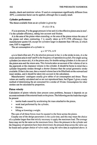


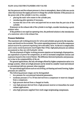


![CIRCUIT ANALYSIS 539
L]
l_r
1/,1 !iTIIF ....
¢,
L._
FIGURE 3 - Pilotcontrol double-actingcylinders.
Remote control by pilot operation
It is often convenient to operate a cylinder from a remote position, as in Figure 3. The main
valve, which is sized to take the full flow, is mounted close to the cylinder and is actuated
by pilot signals from a pair of three-way valves. The main valve in this example is a three-
position, four-way valve. A pilot signal shifts the main valve from the neutral or central
position; removal of the pilot signal allows a spring to return the valve to neutral. In the
central position, the valve traps the air on both sides of the piston; another form of three-
way valve has a central position in which the air is vented from the cylinder. The former
type is more economical in air consumption, the latter allows free movement of the piston
in the central position
Speed control of cylinders
Usually it is desirable to control the speed of movement of a cylinder, at least in one
direction. The most convenient way of doing this is to restrict the air flow in the exhaust
1
FIGURE4- Speed
control double-acting
cylinders.](https://image.slidesharecdn.com/pneumatichandbook-231106162117-d8c7a9ba/85/Pneumatic-Handbook-pdf-538-320.jpg)
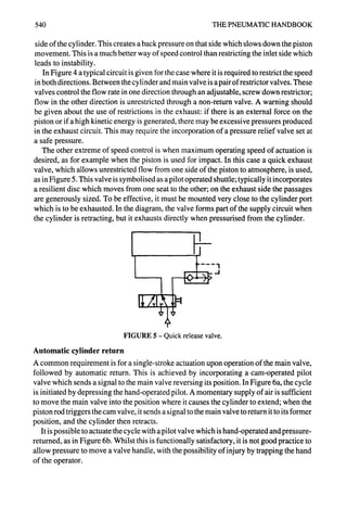


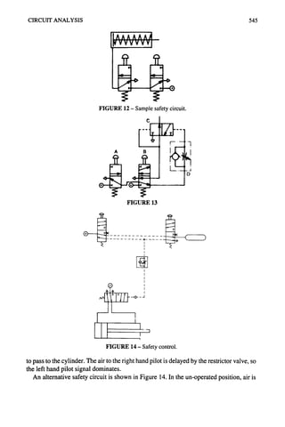


![554 THE PNEUMATIC HANDBOOK
Wrist Rot
Gripper _~ ~, J~,~J,. -".-~, Ii~,.~ ~......,=~.= J
Mounting Kit
Linear Unit --1 ,.
Lin r~o Wrist Rotate
Mounting Kit
Support Bracket for Linear
Base Rotate -
FIGURE 3 - Typical assembly of the various modules showing the use
of adaptor plates. (Parker)
and, in some types, intermediate stroke positions. In addition, it will usually incorporate
speed control valves, which are set during development.
If the user keeps to one supplier, it is possible to use a range of standard mounting kits
to link the modules together, but provided one is prepared to makes one's own connec-
tions, this is not a necessary restriction. Figure 3 shows how the modules can be connected
by the appropriate adaptor plates.
If the velocity of one of the units needs to be governed either to a maximum value or
to ensure that the travel is smooth, without end-of-travel bounce, an air/oil tandem cylinder
may be incorporated. These are discussed in the chapter on Actuators.
Two further modules, which are modifications of the linear unit, are the precision
positioning unit and the gantry unit. The positioning unit allows very precise, infinitely
variable stroke length. One type is shown in Figure 4. Power for movement is supplied by
the internal cylinder and positioning is achieved by a ball screw linked to an incremental
encoder and a magnetic brake. When the encoder signals that the correct position has been
! :~.,,>~% ", ~,, ",
I ii 1 , /] V. 1" 1 .A ~' L I ~i' ./
...... ~7..~.I...T.;-:<I~T~;
....... 7- .... ;...~..:L.~:W-;- -- :_~v
FIGURE 4 - Precision positioning unit employing electromagnetic brake
and ball screws.
D](https://image.slidesharecdn.com/pneumatichandbook-231106162117-d8c7a9ba/85/Pneumatic-Handbook-pdf-553-320.jpg)


![564 THE PNEUMATIC HANDBOOK
Work of depression
The equation governing the work of depression, related to unit volume of free air, is:
W= )' P,[(P2) L~-rl ]
v-I -i
PI is the pressure in the vacuum chamber and P2 is the atmospheric pressure (or the
pressure against which the chamber is evacuated).
Expressed in practical units, this equation becomes
w-0. .]
-
where W is the work rate in kW per l/s of the pump displacement, and the pressures are
in bar.
It will observed that the work is zero for P, = P2 and for Pj = 0. It is a maximum when
dW/dP~ = 0, which occurs when
P2 Y
Pl =T~-'
For diatomic gases (T = 1.4),
P2
- 3.25
Pl
If the vacuum required is lower than is represented by this value of pressure ratio, the
work increases to a maximum and then decreases; the drive to the pump must be capable
of supplying this maximum.
With T = 1.4, the maximum value for the work rate is 0.043 kW per l/s of pump flow.
Conductance
An important concept in vacuum technology is that of conductance in a pipe or an aperture.
It is usually given the symbol U and is defined as:
flow of gas in PV units
pressure difference across the device
The units are litre/s.
For the determination of conductance in various types of flow restriction, reference
should be made to specialist texts, but two of the most common restrictions are long pipes
and apertures, for which the following approximations may be used. For a long pipe of
constant diameter and air at 25°C,
U = O.125 d3/L l/s](https://image.slidesharecdn.com/pneumatichandbook-231106162117-d8c7a9ba/85/Pneumatic-Handbook-pdf-562-320.jpg)


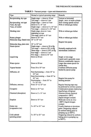


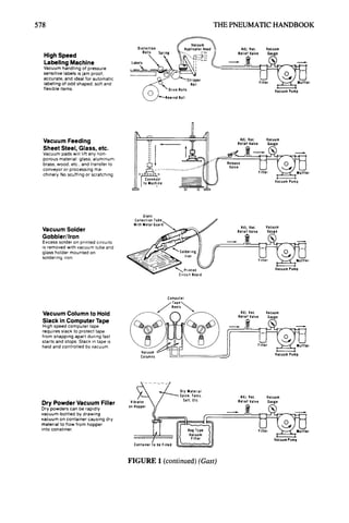
![VACUUM TECHNIQUES 579
FIGURE 2 - Suction cups. Top left: for plane and slightly curved surfaces.
Top fight: flat with cleats for plane surfaces. Bottom left: deep when handling curved
surfaces. Bottom fight: bellow for use when level cc:npensation is required.
Suction cups and pads
A variety of designs of suction cups arc available, for use,,according to the shape of the
surface to which they arc to be attached. Figure 2 shows some typical shapes.
In calculating the holding force of a cup it is customary to take the maximum force as
the product of the area of the inner sealing lip and a pressure corresponding to 75%
vacuum. In addition it is recommended that minimum safety factors of 2 for horizontal
surfaces and 4 for vertical surfaces should be used.
When using vacuum pads, the response time (the time taken for the vacuum to reach the
design level) should be calculated. When using suction for component handling, it is
important the next stage of the operation should not start until the correct depression is
reached. The total internal volume of the pipework and fittings up to the pad should first
be calculated and the formulas in the next chapter used to determine the response time.
Ejector
[ !
Inlet4 bar Exhaust
Vacuum
~ ~,h,Suctionpad
I'T" 4> __..~ 1
l "7" ~"
",~
Safety
valve
r-~-~ L. r ~ ....
Adapter L J_ JI IM~ainl~oressur~va
3bar
.t_J Mainpressurevalve ]-~),-~c:3~?i2a r
/ /
Suction pad with no safety
system.
The suction pad is fitted straight
onto the ejector.
The suction pad is attached
together with a suitable fitting,
straight onto the adapter, to
which the safety valve, main
pressure valve and ejector are
also connected.
FIGURE 3
suction pads with safety system.](https://image.slidesharecdn.com/pneumatichandbook-231106162117-d8c7a9ba/85/Pneumatic-Handbook-pdf-577-320.jpg)


![AIR BLOWERS 583
for the sake of simplicity of production. Because the pressure rise is small the actual
difference in power is usually not significant.
In addition to the power needed to compress the air, there is a further power loss to
overcome friction in the timing gears, bearings and seals as well as dynamic losses in the
compression chamber; the total is of the order of 5%. An advantage of this type of blower
is that, because there is no internal compression, the off-load power is approximately equal
to this small amount.
Positive-displacement blowers
The boundary line between a compressor and a blower is not always clear. One machine
which can be considered as either a blower or a compressor is the helical screw machine
illustrated in Figure 3.
k..o~.,.~: :.,.. ' .. ..
~!~:~:~:~.:~:..". ' " '~~:~:,"~'.'.~':~i~/(~..:..~
-~.k'q~ii~...:;]~':::~"~~ii:" ~,~ ~-:"'.~.~:~:::~,-'.:-~
.~::~.~i
.........~..,...,..::- ..~~i~,.-:.:~m:.. ~ "-:o.~
~ l . . : . . . ~ .... : . ~ ~ ® ~ . . . . " ~ k ~
~ ........
FIGURE 3 - Helical screw blower. (GardnerDenver)
This lies between the helical screw compressor and the Roots blower. It is more efficient
than the Roots (up to 10%, at maximum pressure), but is more expensive to manufacture
because of the complexity of the screw manufacture. It requires timing gears to maintain
correct meshing. This machine can generate a pressure of 1.2 bar or a vacuum of 50 %.
Fan blowers
A fan impeller consists of a number of blades mounted at a pitch angle and assembled on,
or integral with, a hub mounted on a driven shaft. Rotation generates a slip-stream in a
similar manner to an airscrew, although the. efficiency is low compared with a true
airscrew for several reasons: usually the geometric pitch along the length of the blade is
not constant; a large number of blades are provided, which increases the volumetric flow
at the expense of efficiency; the cross-section of the blades is not of aerofoil form, indeed
they are often made from fiat steel plate, curved to an approximate aerodynamic form.
Fans are used to move large volumes of air at very low pressures and are to be found in
ventilation systems, engine and compressor cooling, conveying, vacuum cleaning and
supercharging.
Fan concepts and definitions
The effect of a fan is to change both the static pressure and the air velocity from those
measured upstream of the fan (the inlet) to those measured downstream (the outlet). There
will also be changes in temperature and density but these are small and are frequently](https://image.slidesharecdn.com/pneumatichandbook-231106162117-d8c7a9ba/85/Pneumatic-Handbook-pdf-581-320.jpg)


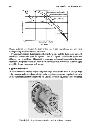


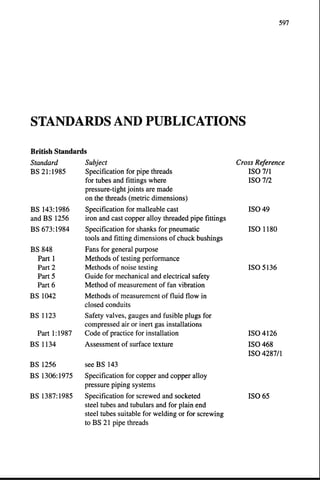


![606 THE PNEUMATIC HANDBOOK
BASIC SYMBOLS (continued)
Description
Square, rectangle.
Diamond.
Miscellaneous
symbols.
Application
Non-return valve, rotary
connection, etc.
Mechanical link, roller, etc.
Semi-rotary actuator.
As a rule, control valve(s),
except for non-return valves.
Conditioning apparatus (filter,
separator, lubricator, heat
exchanger).
Flow line connection.
Spring.
Restriction:
- affected by viscosity
-unaffected by viscosity.
Symbol
©
L;
©l lI, t
[ I]
[ i]
+
1
d~5E
E = thickness of line
A
Description
Triangle:
- solid
- in outline only.
FUNCTIONAL SYMBOLS
Application
The direction of flow and the
nature of the fluid.
Hydraulic flow.
Pneumatic flow or exhaust to
atmosphere.
Symbol
V
~7](https://image.slidesharecdn.com/pneumatichandbook-231106162117-d8c7a9ba/85/Pneumatic-Handbook-pdf-603-320.jpg)


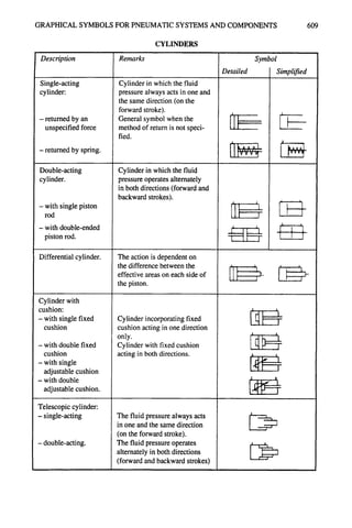
![610 THE PNEUMATIC HANDBOOK
Description
For one type of fluid.
For two types of fluid.
PRESSURE INTENSIFIERS
Remarks
Detailed
Symbol
I Simplified
Air--oil actuator.
eg a pneumatic pressure x is
transformed into a higher
pneumatic pressure y.
eg a pneumatic pressure x is
transformed into a higher
hydraylic pressure y.
Equipment transforming a
pneumatic pressure into a
substantially equal hydraulic
pressure or vice versa.
,
w
0
Description
Method of
representation of
valves.
One single square.
Two or more squares.
Remarks
CONTROL VALVES
Made up of one or more squares
and arrows.
(In circuit diagrams hydraulic and
pneumatic units are normally shown
in the unoperated conditions).
Indicates unit for controlling flow
or pressure, having in operation
an infinite number of possible
positions between its end positions
so as to vary the conditions of flow
across one or more of its ports,
thus ensuring the chosen pressure
and/or flow with regard to the
operating conditions of the circuit.
Indicate a directional control valve
having as many distinct positions
as there are squares. The pipe con-
nections are normally represented
as connected to the box represent-
ing the unoperated condition. The
operating positions are deduced by
imagining the boxes to be dis-
placed so that the pipe connections
correspond with the ports of the
box in question.
Symbol
I]r_
I !
111
! !](https://image.slidesharecdn.com/pneumatichandbook-231106162117-d8c7a9ba/85/Pneumatic-Handbook-pdf-607-320.jpg)
![GRAPHICAL SYMBOLS FOR PNEUMATIC SYSTEMS AND COMPONENTS 611
CONTROL VALVES (continued)
Description Remarks Symbol
Simplified symbol The number refers to a note on
for valves in cases of the diagram in which the symbol I'~
multiple repetition, for the valve is given in full.
DIRECTIONAL CONTROL VALVES
Description
Flow paths:
-one flow path
- two closed ports
- two flow paths
-two flow paths and
one closed port
-two flow paths with
cross connection
-one flow path in a
by-pass position,
two closed ports.
Non-throttling
directional control
valve.
Remarks
Square containing interior lines.
The unit provides distinct circuit
conditions each depicted by a
square.
Basic symbol for two-position
directional control valve.
Basic symbol for three-position
directional control valve.
A transitory but significant
condition between two
distinct positions is optionally
represented by a square with
dashed ends.
A basic symbol for a directional
control valve with two distinct
positions and one transitory
intermediate condition.
Symbol
m
C]
[ 1
• !
I I
J J](https://image.slidesharecdn.com/pneumatichandbook-231106162117-d8c7a9ba/85/Pneumatic-Handbook-pdf-608-320.jpg)

![GRAPHICAL SYMBOLS FOR PNEUMATIC SYSTEMS AND COMPONENTS 613
Description
Directional control
valve 5/2:
- controlled by
pressure in both
directions.
Throttling directional
control:
- with two ports (one
throttling orifice)
- with three ports (two
throttling orifices)
- with four ports (four
throttling orifices).
Electro-hydraulic
servo-valve:
Electro-pneumatic
servo-valve:
- single-stage
- two-stage with
mechanical
feedback
CONTROL VALVES (continued)
Remarks
Directional control valve with
five ports and two distinct
positions.
The unit has two extreme
positions and in infinite number of
intermediate conditions with
varying degrees of throttling.
All the symbols have parallel
lines along the length of the boxes.
Showing the extreme positions
and a central (neutral) positions.
eg tracer valve plunger operated
against a return spring.
eg directional control valve
controlled by pressure against a
return spring.
eg tracer valve, plunger
operated against a return
spring.
A unit which accepts an
analogue electrical signal and
provides a similar analogue
fluid power output.
- with direct operation.
- with indirect pilot-operation.
Symboi
f-l[ I
I ,l
- 1 I
11
I v / ] ! '~11 ~/X, 1
u~ ),.~r:.tl, i~'~ I > "
.i.IJ, "1
T t -
T](https://image.slidesharecdn.com/pneumatichandbook-231106162117-d8c7a9ba/85/Pneumatic-Handbook-pdf-610-320.jpg)


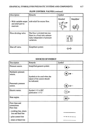


![SBP- Air compressor [Compatibility Mode].pdf](https://cdn.slidesharecdn.com/ss_thumbnails/sbp-aircompressorcompatibilitymode-241227102120-b6a67cde-thumbnail.jpg?width=640&height=640&fit=bounds)


