Downloaded 11 times
![“ Plan-B” An Alternative Liquidation* Strategy of Fukushima Daiichi NPP May 21, 2011 Satoshi Sato [email_address] International Access Corporation *: A term “liquidation” is used in this document to generally mean various activities directly and indirectly associated with restoration of safe state of each affected reactor in Fukushima Daiichi NPP. This follows a precedent in which workers involved in the emergency actions on the Chernobyl site during the accident and the subsequent clean-up operations were called “Liquidators”.](https://image.slidesharecdn.com/plan-bfinal-110704014748-phpapp01/85/Plan-B-1-320.jpg)
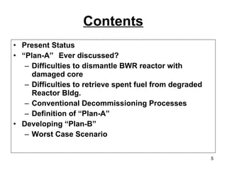
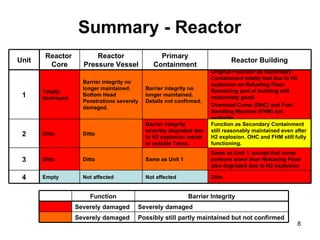
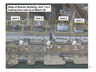
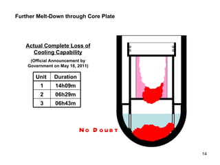
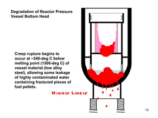
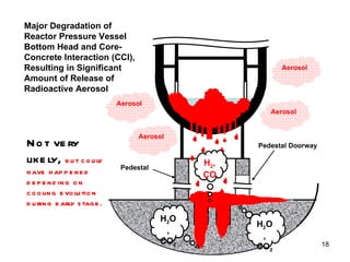
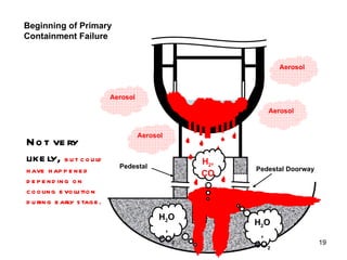
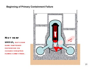
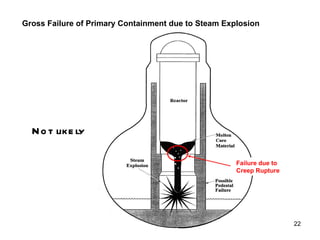
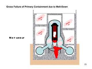
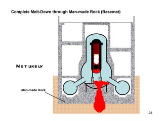
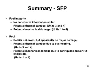

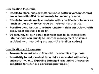


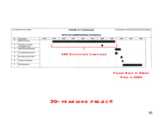
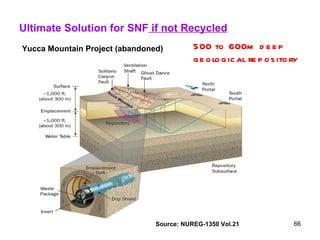
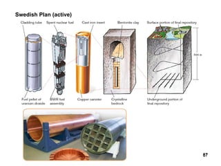

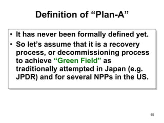
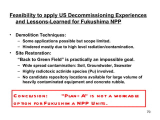
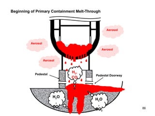
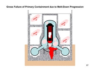
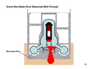
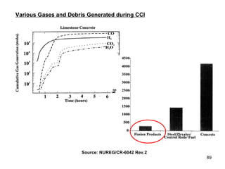
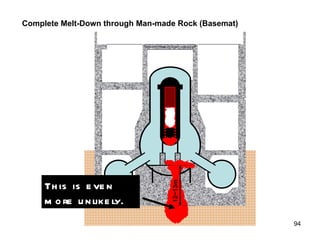

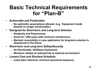
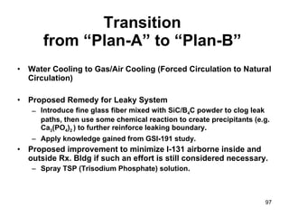

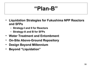


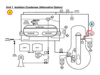
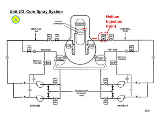
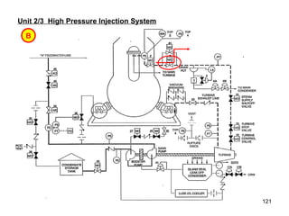
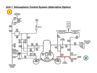
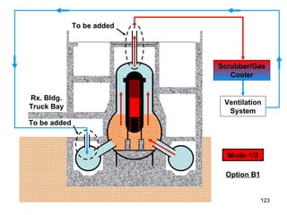
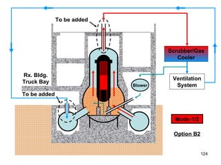
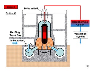
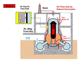


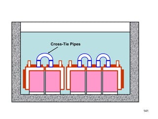
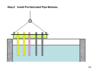
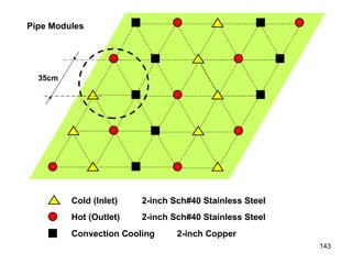
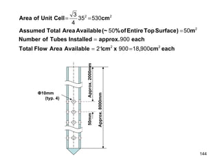
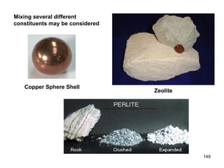
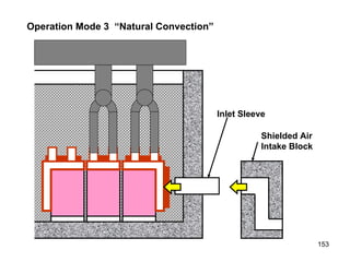
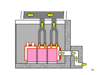
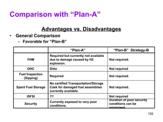
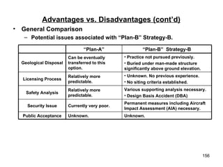
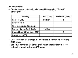
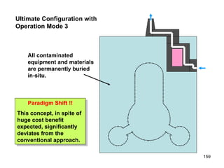

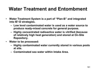


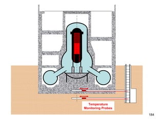
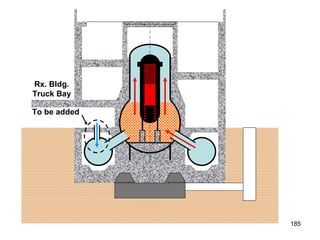


The document discusses potential strategies for decommissioning the damaged Fukushima Daiichi nuclear power plant reactors and spent fuel pools, referred to as "Plan-B Liquidation Strategies". It notes that dismantling the damaged reactors will be extremely challenging due to the harsh radiation environment. Leaving the reactors and spent fuel pools as they are is proposed as one option, but it would require public and regulatory approval.


![5G Explained! A High Level Overview [Introduction]](https://cdn.slidesharecdn.com/ss_thumbnails/5gexplainedahighleveloverview-260119165306-cc137a3e-thumbnail.jpg?width=640&height=640&fit=bounds)


