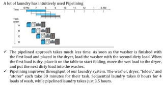
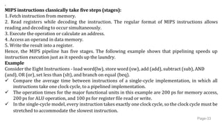
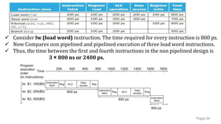
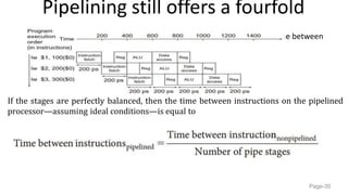
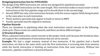
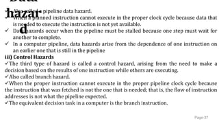
The document discusses pipelining, an implementation technique where multiple instructions are overlapped in execution to improve processor throughput. It provides examples of how pipelining works similarly to an assembly line for laundry, and describes the five stage pipeline of MIPS instructions. The document also discusses pipeline hazards like structural hazards when hardware can't support simultaneous instructions, data hazards when instructions depend on data not yet available, and control hazards from branches.
1. JAI SHRIRAM ENGINEERING COLLEGE, TIRUPPUR – 638 660
Approved by AICTE, New Delhi & Affiliated to Anna University, Chennai
Recognized by UGC & Accredited by NAAC and NBA (CSE and ECE)
PIPELINNING
Prof B.SRITHA M.E(Ph.D)
Assistant Professor
Department of ECE
2. INTRODUCTION
Pipelining is an implementation technique in which multiple instructions are overlapped
in execution.
Example - Real time example of Laundry Service
The non-pipelined approach to laundry would be as follows:
1. Place one dirty load of clothes in the washer.
2. When the washer is finished, place the wet load in the dryer.
3. When the dryer is finished, place the dry load on a table and fold.
4. When folding is finished, ask your roommate to put the clothes away.
3. A lot of laundry has intuitively used Pipelining
The pipelined approach takes much less time. As soon as the washer is finished with
the first load and placed in the dryer, load the washer with the second dirty load. When
the first load is dry, place it on the table to start folding, move the wet load to the dryer,
and put the next dirty load into the washer.
Pipelining improves throughput of our laundry system. The washer, dryer, “folder,” and
“storer” each take 30 minutes for their task. Sequential laundry takes 8 hours for 4
loads of wash, while pipelined laundry takes just 3.5 hours.
4. .
MIPS instructions classically take five steps (stages):
1. Fetch instruction from memory.
2. Read registers while decoding the instruction. The regular format of MIPS instructions allows
reading and decoding to occur simultaneously.
3. Execute the operation or calculate an address.
4. Access an operand in data memory.
5. Write the result into a register.
Hence, the MIPS pipeline has five stages. The following example shows that pipelining speeds up
instruction execution just as it speeds up the laundry.
Example
Consider the Eight Instructions - load word(lw), store word (sw), add (add), subtract (sub), AND
(and), OR (or), set less than (slt), and branch on equal (beq).
Compare the average time between instructions of a single-cycle implementation, in which all
instructions take one clock cycle, to a pipelined implementation.
The operation times for the major functional units in this example are 200 ps for memory access,
200 ps for ALU operation, and 100 ps for register file read or write.
In the single-cycle model, every instruction takes exactly one clock cycle, so the clock cycle must be
stretched to accommodate the slowest instruction.
Page-33
5. Consider lw (load word) instruction. The time required for every instruction is 800 ps.
Now Compares non pipelined and pipelined execution of three load word instructions.
Thus, the time between the first and fourth instructions in the non pipelined design is
3 × 800 ns or 2400 ps.
Page-34
6. Pipelining still offers a fourfold
Performance Improvement the time between
the first and fourth instructions is 3 × 200 ps or 600 ps.
Page-35
If the stages are perfectly balanced, then the time between instructions on the pipelined
processor—assuming ideal conditions—is equal to
7. Designing Instruction Sets for PiPELINING
The design of the MIPS instruction set, which was designed for pipelined execution.
First, all MIPS instructions are the same length. This restriction makes it much easier to fetch
instructions in the first pipeline stage and to decode them in the second stage.
Second, MIPS has only a few instruction formats, with the source register fields being located
in the same place in each instruction.
Third, memory operands only appear in loads or stores in MIPS
Fourth, operands must be aligned in memory.
Pipeline Hazards
There are situations in pipelining when the next instruction cannot execute in the following
clock cycle. These events are called hazards, and there are three different types.
i) Structural hazard
When a planned instruction cannot execute in the proper clock cycle because the hardware does
not support the combination of instructions that are set to execute.
Example: We had a single memory instead of two memories. If the pipeline had a fourth
instruction, see that in the same clock cycle the first instruction is accessing data from memory
while the fourth instruction is fetching an instruction from that same memory. Without two
memories, pipeline could have a structural hazard.
Page-36
8. Data
hazar
d
Page-37
Also called a pipeline data hazard.
When a planned instruction cannot execute in the proper clock cycle because data that
is needed to execute the instruction is not yet available.
Data hazards occur when the pipeline must be stalled because one step must wait for
another to complete.
In a computer pipeline, data hazards arise from the dependence of one instruction on
an earlier one that is still in the pipeline
iii) Control Hazards
The third type of hazard is called a control hazard, arising from the need to make a
decision based on the results of one instruction while others are executing.
Also called branch hazard.
When the proper instruction cannot execute in the proper pipeline clock cycle because
the instruction that was fetched is not the one that is needed; that is, the flow of instruction
addresses is not what the pipeline expected.
The equivalent decision task in a computer is the branch instruction.