Download to read offline


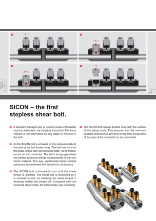

1. The document describes a new type of shear bolt connector system called SICON that has advantages over conventional shear bolt designs. 2. SICON bolts have no predetermined breaking points, ensuring optimal thread loading for any size conductor. This allows for significantly higher contact pressures, especially with aluminum conductors. 3. When fully tightened, the SICON bolt breaks smoothly at the surface of the clamp body, keeping protrusion to a minimum for different conductor sizes.


