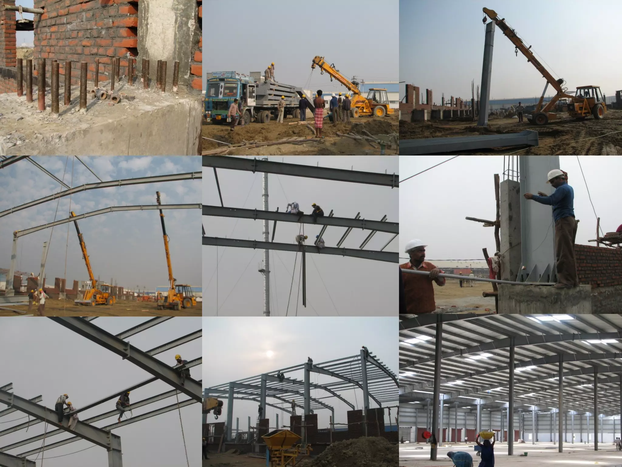
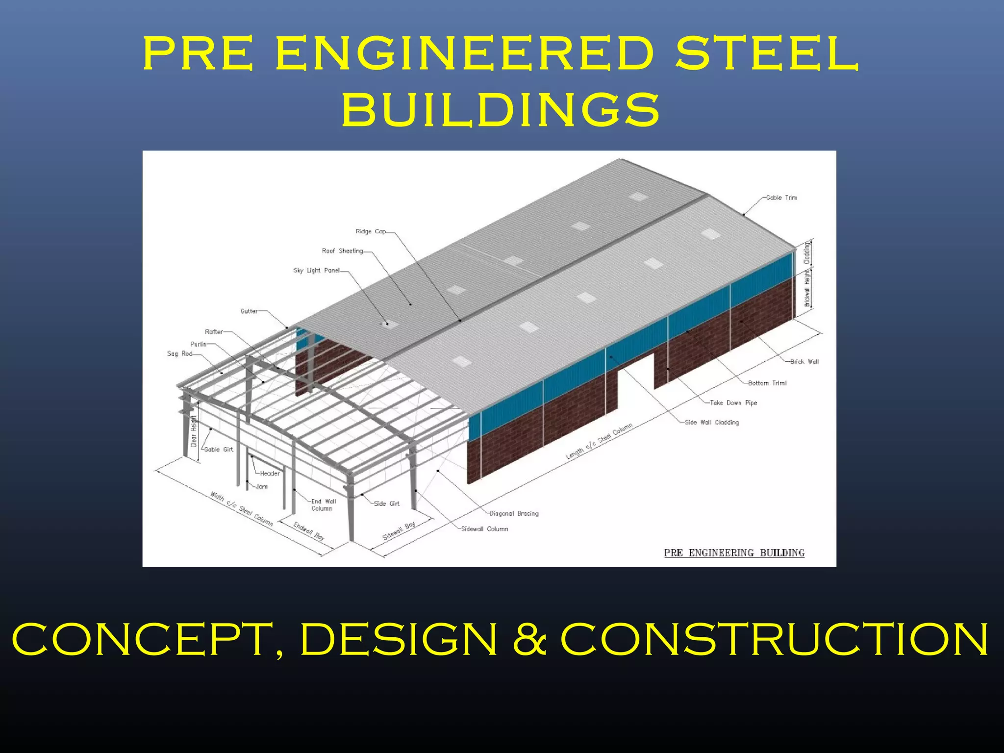
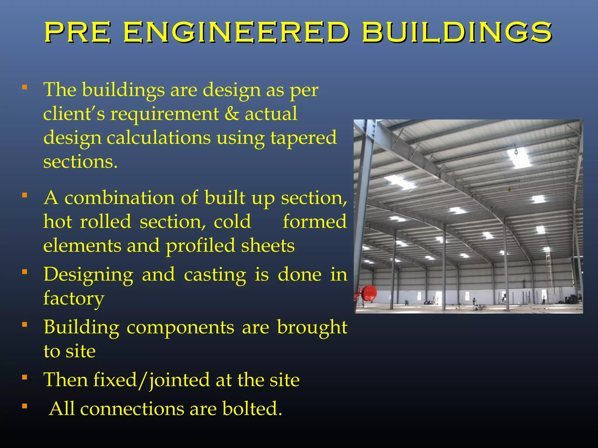
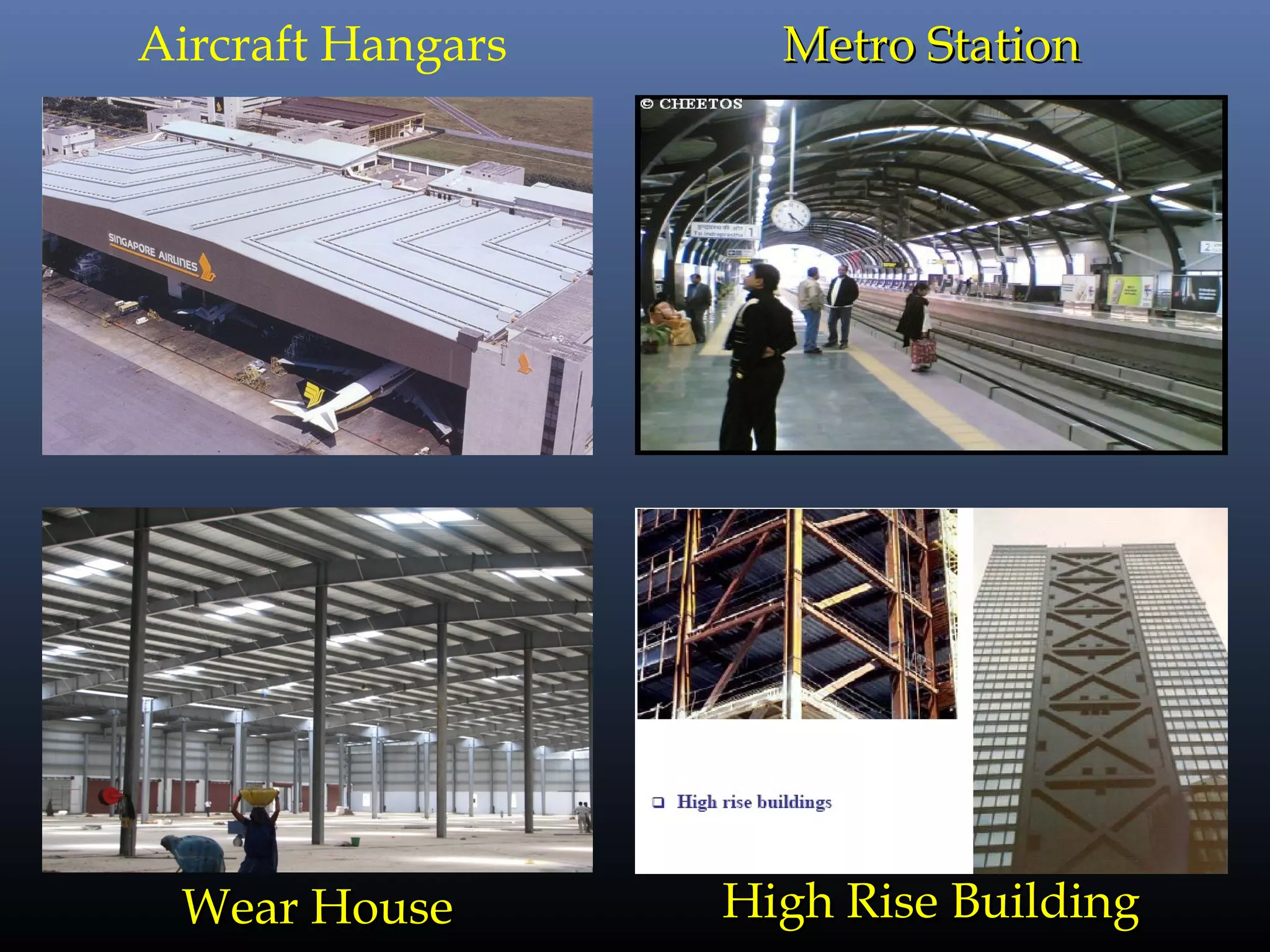
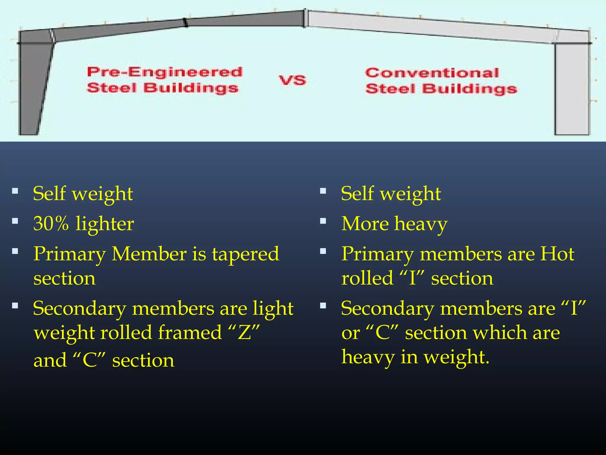
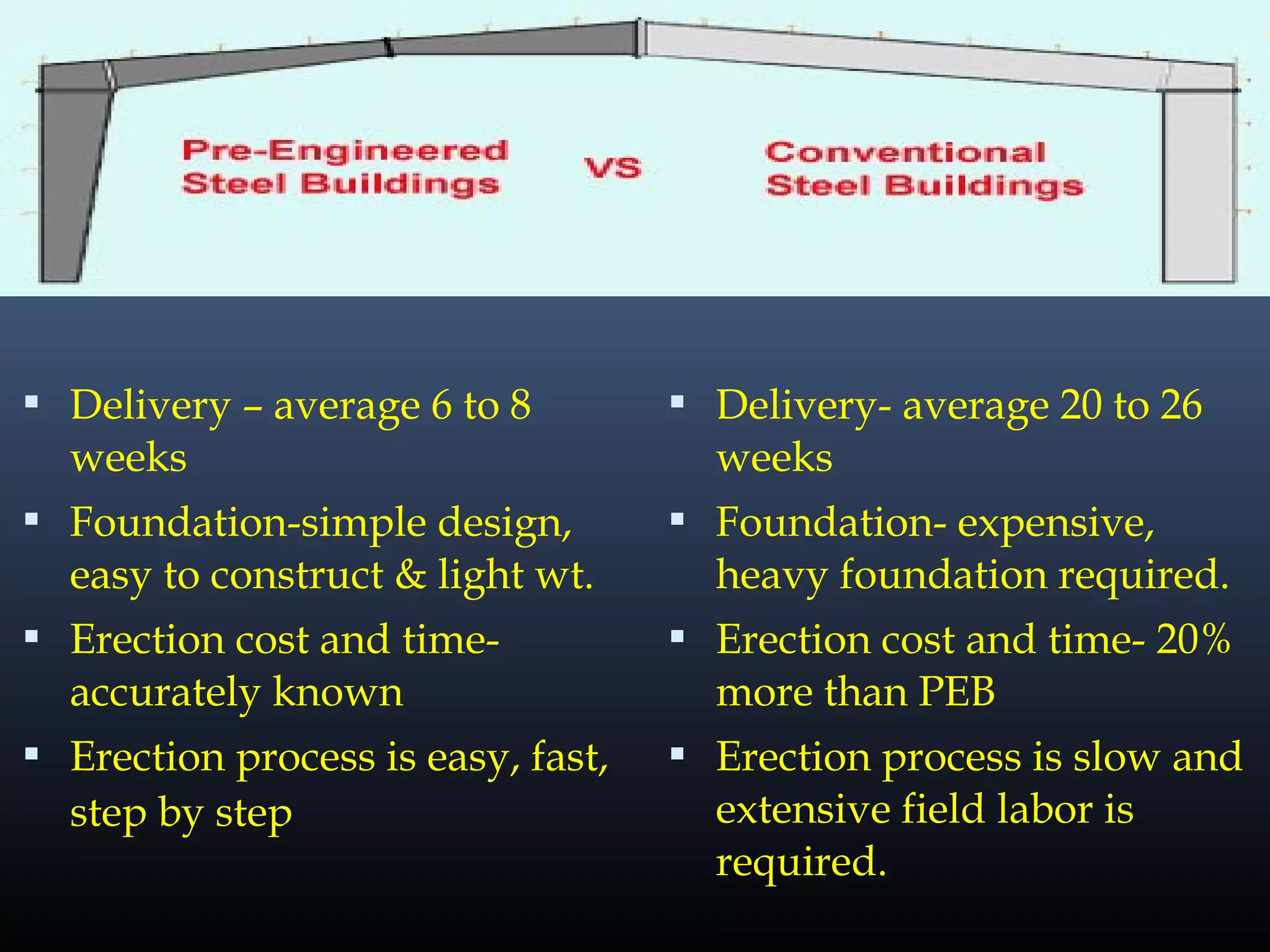
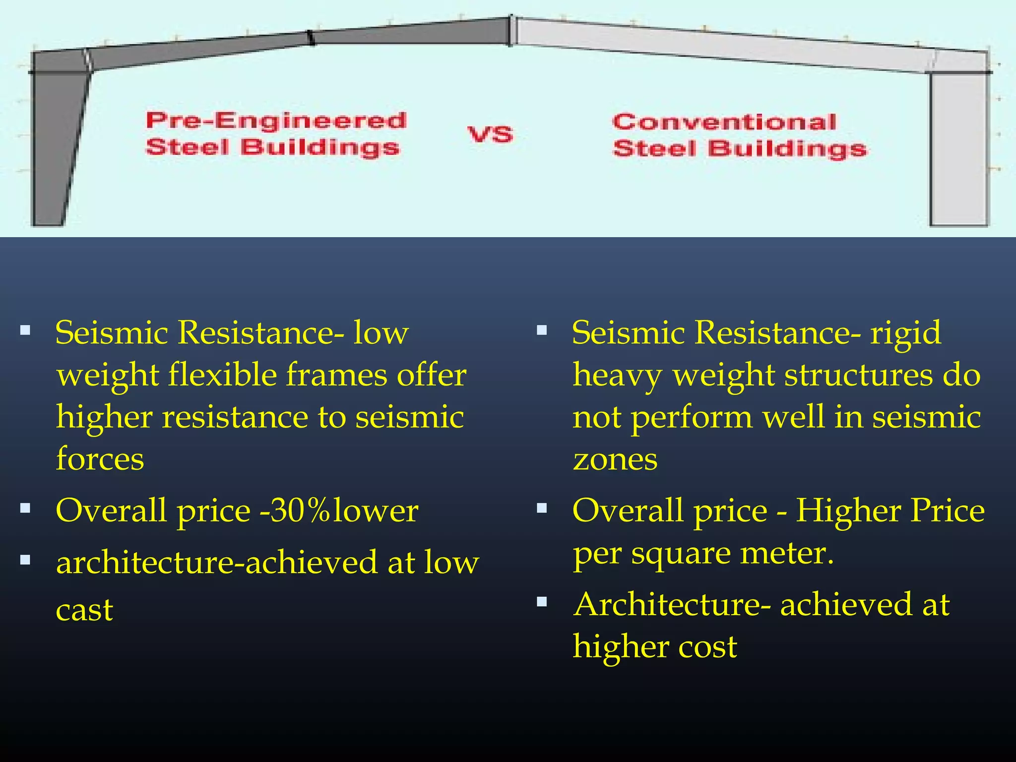
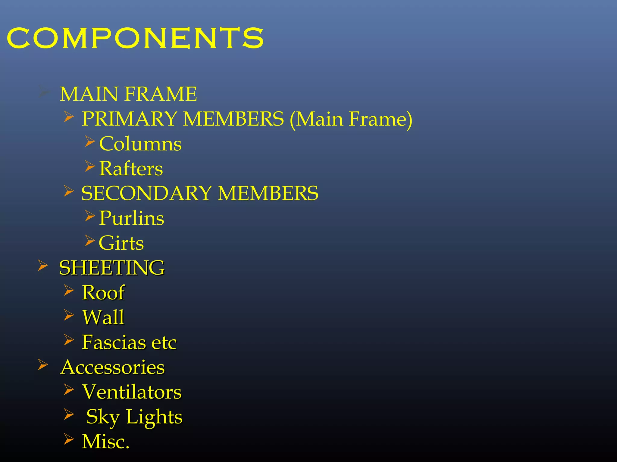
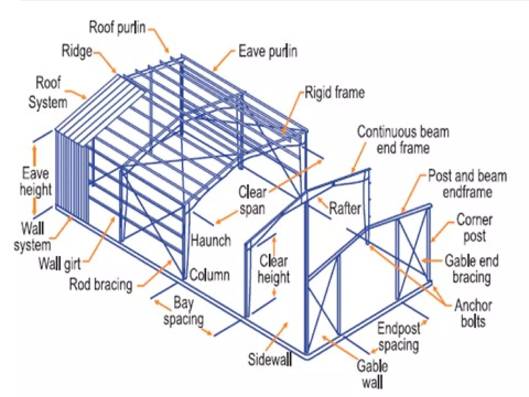
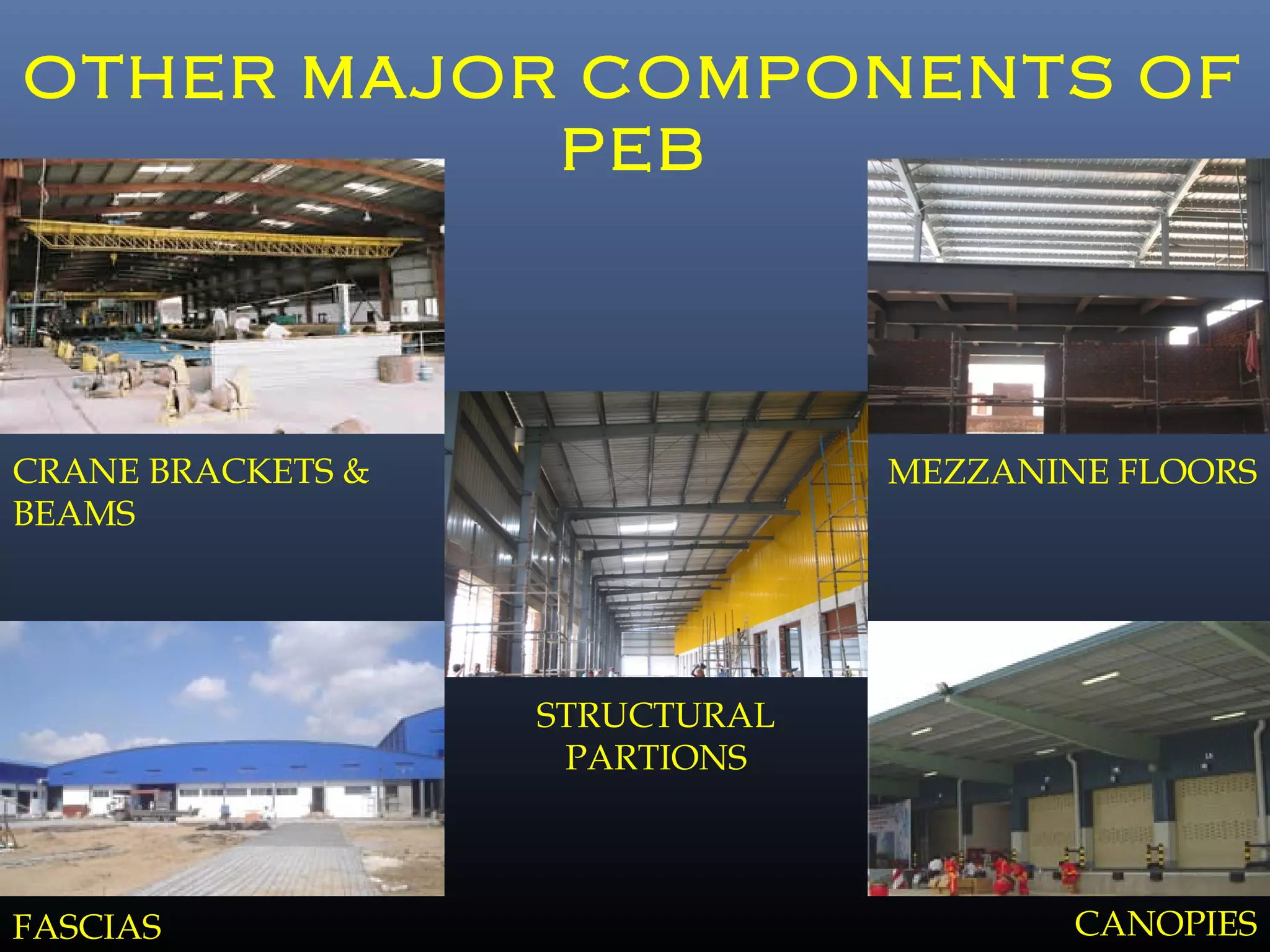
Pre-engineered steel buildings are designed and fabricated off-site using standardized structural components. They are lighter and more economical than conventional construction. The key components include tapered steel columns, rafters, purlins, girts, and sheet metal panels. Structural analysis and design are performed to calculate loads and optimize the frame based on factors like wind speed and seismic zone. Components are then erected on-site by connecting prefabricated pieces together using bolted joints.
![GUIDELINES FOR PEB DESIGN AT
PROPOSAL STAGE
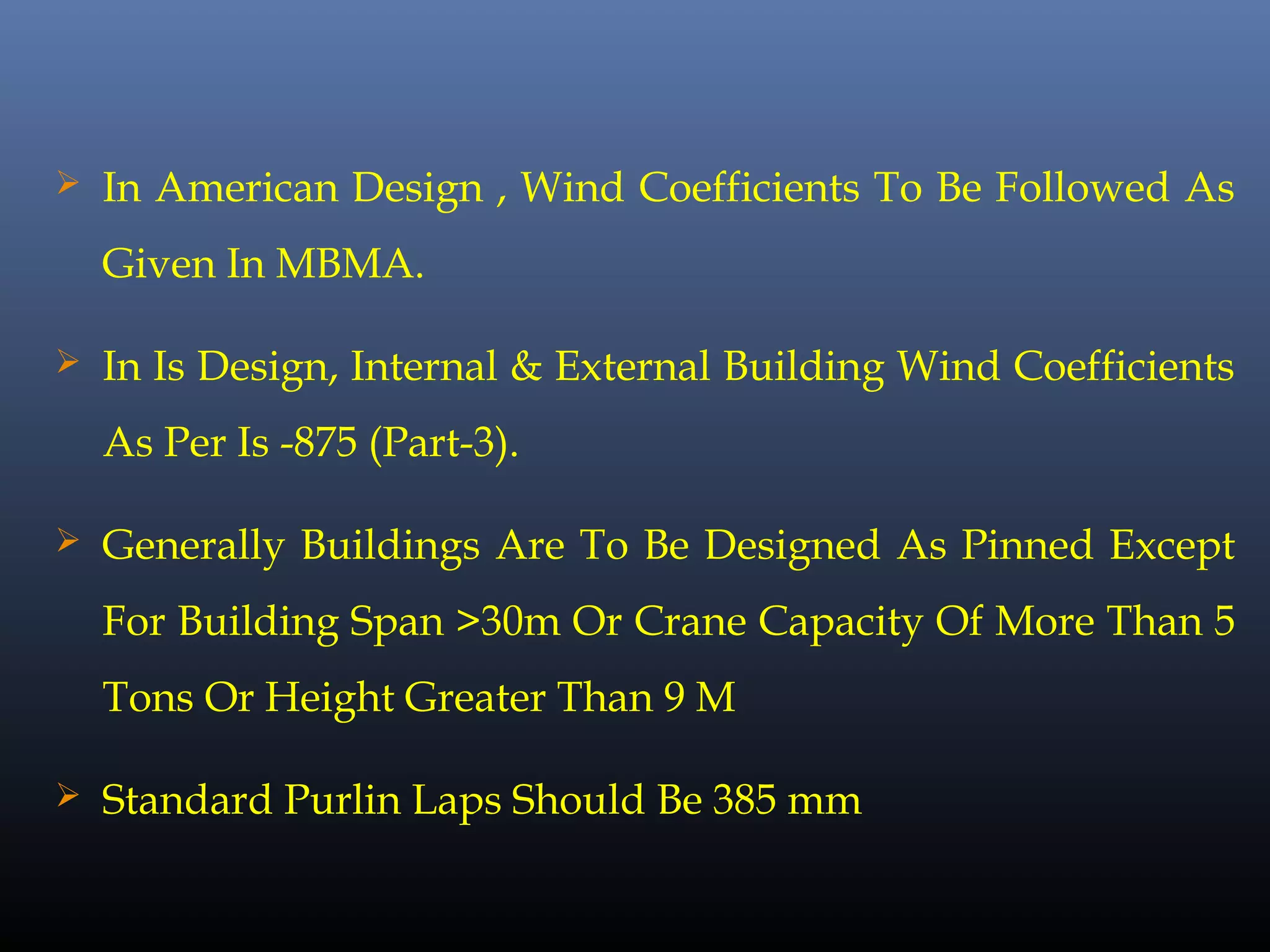
All Designs Shall Be As Per MBMA [Metal Building
Manufacturer Association] &Client Specifies As Per Is
Code.
Live load as Per American Code = 0.57 KN/M2
and as
Per IS Code = 0.75 KN/M2
. (Reduction in live load to be
incorporated for buildings having higher slopes)
As Per American Code :Horizontal Deflection = L/180 &
Vertical Deflection = eh/100 For Main Frames.
Wind terrain category 3 is to be selected unless more data
is available.](https://image.slidesharecdn.com/pebstructures-150329083830-conversion-gate01/75/Peb-structures-17-2048.jpg)