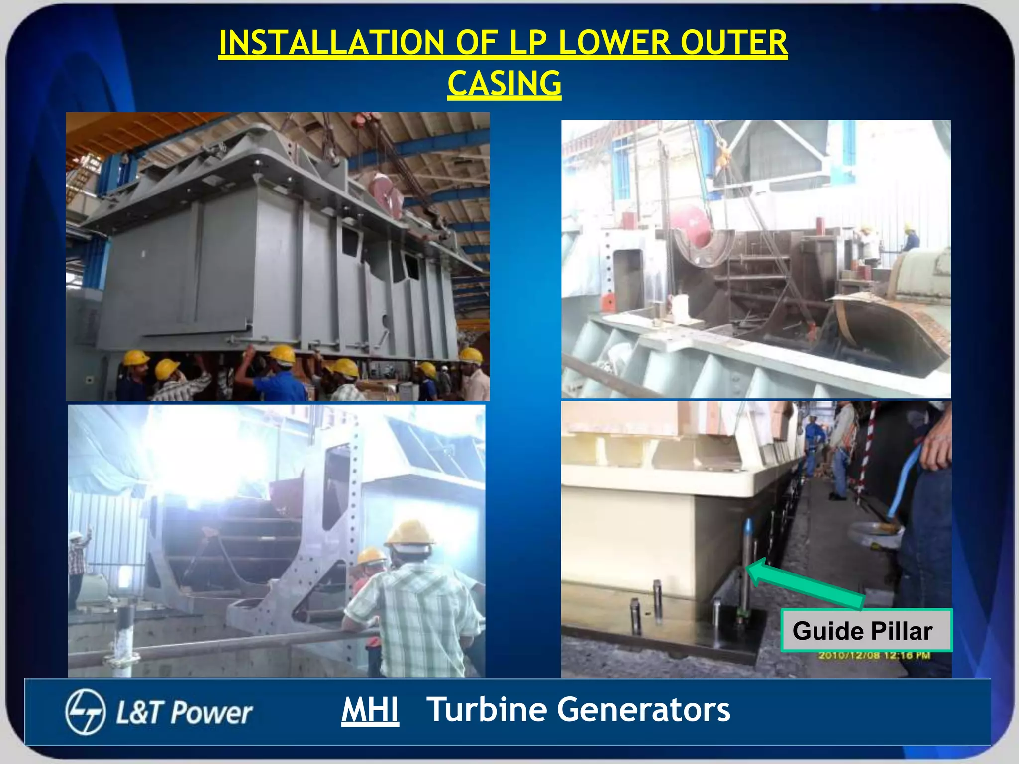
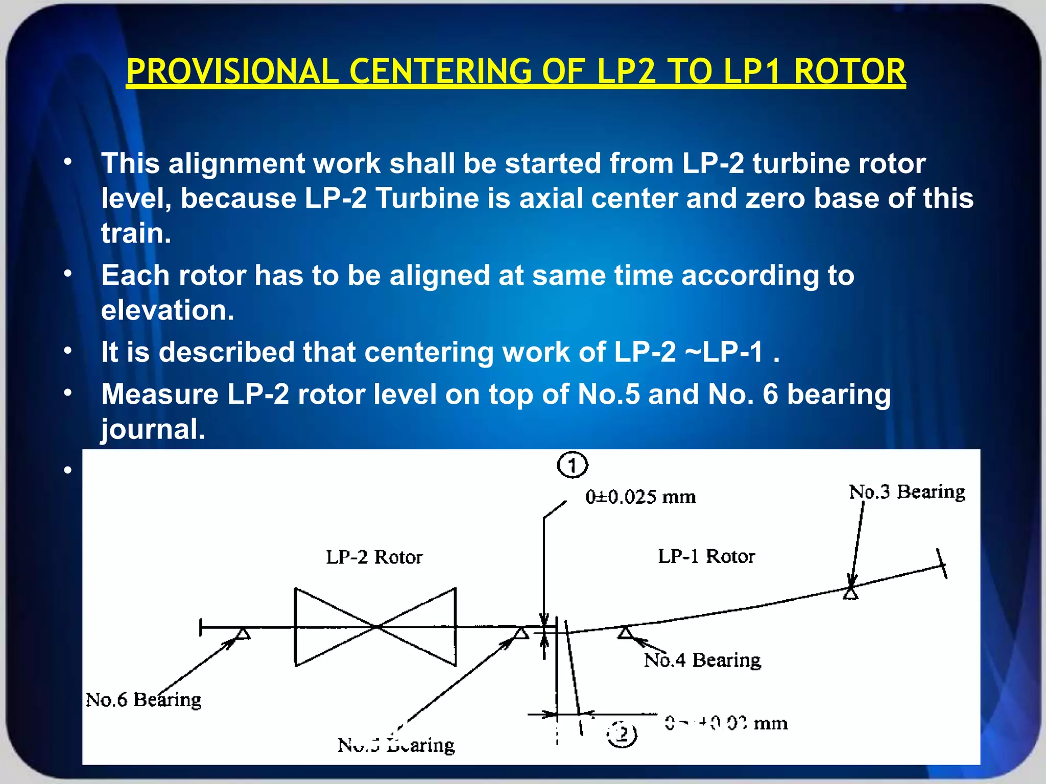
SUMMER TRAINING AT 2X700 MW
RAJPURA THERMAL POWER
PLANT, PUNJAB
LARSEN & TOUBRO
LARSEN & TOUBRO
MHI Turbine Generators
INTRODUCTION
TRAINING TOPIC : TURBINE ERECTION
•
• TRAINING LOCATION : 2X700 MW RAJPURA THERMAL POWER
PLANT, PUNJAB
TRAINING DURATION : 20.06.2013 TO 10.08.2013
•
•
LARSEN & TOUBRO
It’s all about Imagineering
TURBINE ERECTION FLOW CHART
STEP-1
Centering Of
Turbine Foundation
STEP-2
Setting of levelling Plates
and Levelling Wedges
STEP-3
Setting of Turbine
seatingPlates
S
S
T
T
E
P
E
P
-
-
4
4
IInnsstaltalllatatiionon
of
ofLP
LP O
Ou
ute
ter
r
ccasasiinngg
STEP-4
Installation of LP
Outer casing
SSTTEP
EP
-
5
-
5
I
In
ns
stal
tall
lat
ati
ion
on of
of
H
HI
IP
P M
Mod
odu
ul
le
e
an
and
d H
HP
P/
/I
IP
P
PPeeddeesstaltal
STEP-5
Installation of HIP
Module and HP/IP
Pedestal
SSTTEP
EP
-
6
-
6
Levelling & centerin
Of LP-1 and LP-2
Casing
STEP-6
Levelling & centeringg
Of LP-1 and LP-2
Casing
SSTTEP
EP
-
7-
7
IInnsstaltalll
b
b
e
e
a
r
a
r
i
i
n
n
g
g
s
sanandd
RRotorotorss
STEP-7
Install bearings
and Rotors
SSTETEP
P
-
8
-
8
Provisional centering
Of LP-1 & LP-2
STEP-8
Provisional centering
Of LP-1 & LP-2
SSTTEP
EP
-
9-
9
PPrroviovissiiononalal
c
c
e
e
n
n
t
t
e
e
r
r
i
i
n
n
g
go H
H
I
I
P
P&
&
LP
LP
1
1 R
Roto
otor
r
P
STEP-9
rovisional centering off
HIP & LP 1 Rotor
SSTTEPEP-10-10
Installation of inner
Parts of LP casing
(Pre Assembly)
STEP-10
Installation of inner
Parts of LP casing
(Pre Assembly)
SSTTEPEP-1
1-1
1
2
2n
nd
d c
ce
en
nt
te
er
ri
in
ng
g
of
of H
HI
IP
PT
Tu
ur
rb
bi
in
ne
e –
–
L
LP
P T
T
u
u
r
r
b
b
i
i
n
STEP-11
2nd centering of HIP
Turbine –LP Turbinnee
SSTTEPEP-12-12
F
Fi
in
nal
al A
As
ss
se
em
mb
bl
ly
y
STEP-12
Final Assembly
STEP-15
Oil Flushing
S
STE
TEP
P-
13
-13
Grouting
STEP-14
Checking Final
Coupling alignment
And coupling
STEP-16
Final assembly of
Pedestal Turning gear
& others
MHI Turbine Generators
CENTERING OF TURBINE FOUNDATION
•
•
•
•
•
The basic centerline of the turbine and generator
foundation shall be confirmed according to the
foundation drawing.
The position of foundation bolts and anchor blocks
from the centerline of turbine shall be confirmed and
recorded.
The basic centerline of turbine shall be check by
optical scope.
Optical scope shall be on referance elevation mark.
Top surface of the foundation shall be chipped.
MHI Turbine Generators
SETTING OF LEVELLING PLATES & LEVELLING
WEDGES
• Leveling plates and leveling wedges shall be fixed
by grouting to their correct position with a level
wedge shall be consider with “Rotor alignment
curve”.
MHI Turbine Generators
SETTING OF TURBINE SEATING PLATES
•
•
•
•
•
Before setting of seating plate, contact should be cleaned and
each seating plate shall be located and be set on its correct
position.
Adjusting bolts shall be installed on the seating plate with
thread paste.
After seating plates in place, a piano wire shall be stretched on
between the centerline of the turbine, then accurate centering
of each seating plate shall be made according to this piano
wire. Tolerance shall be not more than +/-2mm from centerline.
Elevation tolerance : 0~ -0.5 mm
Each seating plate shall be adjusting bolts and leveling
wedges. To measure the height of the seating plate to surface,
using straight-edge with level vial. Permissible tolerance is
within 0.25MM/M.
MHI Turbine Generators
SETTING OF TURBINE SEATING
PLATES
Seating plate
Adjusting bolt
MHI Turbine Generators
INSTALLATION OF LP LOWER OUTER
CASING
•
•
The machined surface of seating plate , machined
contact lower surface of horizontal joint and vertical
joint shall be cleaned before installation of LP
turbine. And checked to find damage such as
scratch. And if scratches are found surface shall be
smoothed up by oil stone before installation.
Surface of seating plates shall be thinly coated with
anti-seazing compound is equivalent to Molykote G-
n.
MHI Turbine Generators
INSTALLATION OF LP LOWER OUTER
CASING
Guide Pillar
MHI Turbine Generators
INSTALLATION OF HP PEDESTAL & HIP MODULE
•
•
•
The machined surface of seating plate , machined
contact lower surface of horizontal joint and vertical
joint shall be cleaned before installation of HIP
Pedestal. And checked to find damage such as
scratch. And if scratches are found surface shall be
smoothed up by oil stone before installation.
Surface of seating plates shall be thinly coated with
anti-seazing compound is equivalent to Molykote G-
n.
Prior to installing the HIP module, both side of the
centering beam shall be fitted to LP-1 pedestal and
HP pedestal temporary.
MHI Turbine Generators
3D VIEW OF HIP PEDESTAL SEATING PLATE
& HIP PEDESTAL
MHI Turbine Generators
HIP Extension Shaft
HIP Pedestal
HIP Extension Shaft
Guide Pillar for HIP Module
MHI Turbine Generators
LEVELLING & CENTERING OF HIP, LP1 AND LP2
CASING
•
•
•
Lower casing shall be adjusted to level and elevation at
the horizontal joint using automatic/ level edge with level
vial. Adjustment shall be performed using jacking bolts,
levelling wedge and shim liner of seating plate. Then the
target level of horizontal joint of LP casing shal be with
0.25mm/m.
Piano wire shall be re-set the centerline of turbine
generator. Each casing center (LP-2 casing,LP-1 casing)
shall be aligned and installed with scale within 1 mm
target to piano wire as standard line by moving casing
and seating plate together.
Finally, relative location of each part (HP pedestal, HIP
casing,LP-1 casing, LP-2 casing) should be measured the
distance from center line of each parts.
MHI Turbine Generators
Levelling of HIP Pedestal by
optical scope
HIP Pedestal
Seating plate
Leveling Wedge
MHI Turbine Generators
INSTALL BEARING
• Prior to installation of rotor No 1 and No 2 bearings shall
be installed, and each bearing (No. 3. No. 4, No.5, No.6)
shall be installed with sperical key. And each bearing
shall be conformed contact mark with Blue check paint
so that there is more than 75% contact.
Bearing
MHI Turbine Generators
INSTALL LP ROTOR
MHI Turbine Generators
Contact check
Blue paste apply on
Journal
Journal
Bearing
Guide Pillar
Bearing Bottom
surface
Jacking Oil Inlet
MHI Turbine Generators
PROVISIONAL CENTERING OF LP2 TO LP1 ROTOR
•
•
•
•
•
This alignment work shall be started from LP-2 turbine rotor
level, because LP-2 Turbine is axial center and zero base of this
train.
Each rotor has to be aligned at same time according to
elevation.
It is described that centering work of LP-2 ~LP-1 .
Measure LP-2 rotor level on top of No.5 and No. 6 bearing
journal.
And rotor level shall be adjusted by seating plate for pedestal
utilizing jacking bolt, levelling wedge and/or shim liner, if
necessary.
MHI Turbine Generators
PROVISIONAL CENTERING OF LP 1 to HIP TURBINE
•
•
Measure LP-1 rotor level on top of No.3 and No.4 bearing
journal.
And rotor level shall be adjusted by seating plate for
pedestal utilizing jacking bolt,leveling wedge and/or shim
liner, if necessary.
MHI Turbine Generators
ALIGNMENT OF LP-2~LP-1 TURBINE ROTOR
LP 1 Rotor
MHI Turbine Generators
BEARING ALIGNMENT CURVE
MHI Turbine Generators
INSTALLATION INNER PARTS OF LP TURBINE
(PRE-ASSEMBLY)
•
•
•
Prior to install inner parts, it’s shall be cleaned by
solvent such as kerosene to remove anti-corrosion
coat. Also machined surface shall be conformed
smooth by oilstone. Finally, nerrow areas of inner
parts such as bolt hole, keyhole,groove and drain
hole shall be cleaned by air blow.
Before lifting Inner casing check sealing, D cycle,
and chain block it should not damage. Use two
sealing and Two chain block for lifting Inner casing.
Check Its radial key it should be properly welded.
MHI Turbine Generators
Check Its radial key it should
be properly welded
Lift the inner lower casing and check
level it should be equal in four
machine corner if not equal then make
equal by chain block.
Radial Pin
MHI Turbine Generators
Install Inner casing carefully.
Install Steam chamber
Install Blade Ring Install Sp. Stationary Blade
MHI Turbine Generators
Install Flow Guide
MHI Turbine Generators
RECORD OF CLEARANCE
•
•
•
•
•
•
•
•
•
Prior to install LP-1, LP-2 rotors, lead wire shall be put on
each stage labyrinth fin to measure clearance.
LP 1 and LP 2 Rotor shall be installed.
Radial clearance (Right & left) & Axial clearance
measured by taper guage and Fillar guage.
Install Upper inner casings to measure upper labyrinth
clearance.
Tighten casing bolt to fit upper and lower casing.
upper inner casings and rotors shall be taken out from
the casing. Lead wire shall be taken out for measurement.
Each clearance shall be considered about “Rotor and
casing deflection”.
LP-1 and LP-2 Rotor shall be installed again.
Amount of rotor movement from K position and total float
of each rotor shall be measured and recorded.
MHI Turbine Generators
INSTALL LEAD WIRE ON ROTOR AND INNER CASING
Instal Lead wire
MHI Turbine Generators
Reamar bolt tightning
Lifting of inner casing
Lead Wire remove
MHI Turbine Generators
HIP INTERNALS
Thermal Shield (IP)
IP Blade Ring
Dummy Ring #1 (MS)
MHI
HP INNER CASING
Turbine Generators
MHI Turbine Generators
2nd CENTERING OF TURBINE
•
•
•
•
The centering of LP 2 turbine and LP 1 turbine shall be carried
out by movement of LP-1 rotor.
The centering of LP 1 turbine and HIP turbine shall be carried
out by movement of HIP rotor.
The centering of LP 2 turbine and generator shall be carried out
by movement of the generator rotor.
Zero points marked on the each rotor shall be turned through
180 degree and placed at the bottom and the clearance
between the matching coupling faces measured.
Alignment of LP 2~ LP 1
SETTING OF THE ADJUSTING LINER & BUSH FOR
TIE BEAM
•
•
The clearance between Tie beam and casing will be checked
and recorded.
After insert of the pin for Tie beam, the bush shall be machined
to its regular thickness at the site and shall be set. After
setting, the bush shall be tack welded to lock.
MHI Turbine Generators
SEATING OF THE ADJUSTING LINER FOR ANCHOR
BLOCKS
•
•
•
Before setting of the adjusting liner for anchor block, the
inclination of surface of anchor blocks shall be conformed.
( Tolerance of inclination of surface +/- 1.5mm )
After confirmation of the inclination of anchor blocks. The
adjusting liners for anchor blocks shall be machined to its
regular thickness at site.
Adjjusting Liinersettttiing Adjjusting Liiner Machiiniing
MHI Turbine Generators
FINAL ASSEMBLY
•
•
After completion of the measurements and verification of
clearance, final assembly shall be commenced. Each parts
shall be cleaned by compressed air prior to the final assembly.
All Inner casing stud bolt will be tightned by Hot Tightning.
Blade ring Install Steam chamber Install
MHI Turbine Generators
Inner casing Install
Bolt Tightning
MHI Turbine Generators
Outer casing
Flow Guide inside OC Outer Casing installation
MHI Turbine Generators
Step 12
Guide Pillar
Level Checking
Bolt Tightning
MHI Turbine Generators
Guide Pillar
Level Checking
Bolt Tightning
MHI Turbine Generators
GROUTING
•
•
•
•
After completion of 2nd centering of turbine and
generator the grouting stopper shall be installed
around the turbine casing, pedestal and generator.
Grouting shall be carried out when the tubine has
been assembled and is loaded with almost all related
weightupon it.
Cleaned the places to be grouted by blowing air and
washing with water.
Fill the clerance between foundation bolt and
sleeves with grout just before grouting.
MHI Turbine Generators
CHECKING OF FINAL COUPLING ALIGNMENT
AND COUPLINGS
 After completion of installing the turbine, couplings of the
turbine to generator shall be checked for HIP=LP-1=LP-
2=GEN alignment and be readjusted if necessary.
 Coupling reamer bolts shall be installed Tightened and
controlled by streatched length of bolts,Tightened value of
coupling reamer bolts
– HIP ~ LP-1 Coupling Bolts = 0.375 ~ 0.431mm
– LP-1 ~ LP-2 Coupling Bolts = 0.432~ 0.497mm
– LP-2 ~ GEN Coupling Bolts = 0.623 ~ 0.717mm
 Thrust bearing assembly and clearance check.
MHI Turbine Generators
OIL FLUSHING, FINAL ASSEMBLY OF
PEDESTAL, TURNING GEAR, COUPLING
GUARD AND OTHERS
•
•
•
•
•
 Oil Pipping Flushing
 The purpose of oil flushing prior to operation of turbine
generator is to flush from oil system of foreign material
wich instruded in the system during the installation stage.
After completion of Oil flushing, Top half of each Journal
bearing and thrust bearing shall be installed finally.
Turbine supervisiory equipment (differential expansion pick up,
vibration pick up, essentricity pick up, speed pick up, etc) and
other accessories shall be installed finally.
Coupling Guard (HIP,LP-1/LP-2,GEN) shall be set.
Bearing cover and pedestal cover shall be installed.
Turning device shall be set according to the designed back
lash & tooth contact obtained and set dowel pin.
MHI Turbine Generators

pdfslide.net_presentation-of-turbine-erection-1.pptx

  • 1.
    SUMMER TRAINING AT2X700 MW RAJPURA THERMAL POWER PLANT, PUNJAB LARSEN & TOUBRO LARSEN & TOUBRO
  • 2.
    MHI Turbine Generators INTRODUCTION TRAININGTOPIC : TURBINE ERECTION • • TRAINING LOCATION : 2X700 MW RAJPURA THERMAL POWER PLANT, PUNJAB TRAINING DURATION : 20.06.2013 TO 10.08.2013 • • LARSEN & TOUBRO It’s all about Imagineering
  • 3.
    TURBINE ERECTION FLOWCHART STEP-1 Centering Of Turbine Foundation STEP-2 Setting of levelling Plates and Levelling Wedges STEP-3 Setting of Turbine seatingPlates S S T T E P E P - - 4 4 IInnsstaltalllatatiionon of ofLP LP O Ou ute ter r ccasasiinngg STEP-4 Installation of LP Outer casing SSTTEP EP - 5 - 5 I In ns stal tall lat ati ion on of of H HI IP P M Mod odu ul le e an and d H HP P/ /I IP P PPeeddeesstaltal STEP-5 Installation of HIP Module and HP/IP Pedestal SSTTEP EP - 6 - 6 Levelling & centerin Of LP-1 and LP-2 Casing STEP-6 Levelling & centeringg Of LP-1 and LP-2 Casing SSTTEP EP - 7- 7 IInnsstaltalll b b e e a r a r i i n n g g s sanandd RRotorotorss STEP-7 Install bearings and Rotors SSTETEP P - 8 - 8 Provisional centering Of LP-1 & LP-2 STEP-8 Provisional centering Of LP-1 & LP-2 SSTTEP EP - 9- 9 PPrroviovissiiononalal c c e e n n t t e e r r i i n n g go H H I I P P& & LP LP 1 1 R Roto otor r P STEP-9 rovisional centering off HIP & LP 1 Rotor SSTTEPEP-10-10 Installation of inner Parts of LP casing (Pre Assembly) STEP-10 Installation of inner Parts of LP casing (Pre Assembly) SSTTEPEP-1 1-1 1 2 2n nd d c ce en nt te er ri in ng g of of H HI IP PT Tu ur rb bi in ne e – – L LP P T T u u r r b b i i n STEP-11 2nd centering of HIP Turbine –LP Turbinnee SSTTEPEP-12-12 F Fi in nal al A As ss se em mb bl ly y STEP-12 Final Assembly STEP-15 Oil Flushing S STE TEP P- 13 -13 Grouting STEP-14 Checking Final Coupling alignment And coupling STEP-16 Final assembly of Pedestal Turning gear & others MHI Turbine Generators
  • 4.
    CENTERING OF TURBINEFOUNDATION • • • • • The basic centerline of the turbine and generator foundation shall be confirmed according to the foundation drawing. The position of foundation bolts and anchor blocks from the centerline of turbine shall be confirmed and recorded. The basic centerline of turbine shall be check by optical scope. Optical scope shall be on referance elevation mark. Top surface of the foundation shall be chipped. MHI Turbine Generators
  • 5.
  • 6.
    SETTING OF LEVELLINGPLATES & LEVELLING WEDGES • Leveling plates and leveling wedges shall be fixed by grouting to their correct position with a level wedge shall be consider with “Rotor alignment curve”. MHI Turbine Generators
  • 7.
    SETTING OF TURBINESEATING PLATES • • • • • Before setting of seating plate, contact should be cleaned and each seating plate shall be located and be set on its correct position. Adjusting bolts shall be installed on the seating plate with thread paste. After seating plates in place, a piano wire shall be stretched on between the centerline of the turbine, then accurate centering of each seating plate shall be made according to this piano wire. Tolerance shall be not more than +/-2mm from centerline. Elevation tolerance : 0~ -0.5 mm Each seating plate shall be adjusting bolts and leveling wedges. To measure the height of the seating plate to surface, using straight-edge with level vial. Permissible tolerance is within 0.25MM/M. MHI Turbine Generators
  • 8.
    SETTING OF TURBINESEATING PLATES Seating plate Adjusting bolt MHI Turbine Generators
  • 9.
    INSTALLATION OF LPLOWER OUTER CASING • • The machined surface of seating plate , machined contact lower surface of horizontal joint and vertical joint shall be cleaned before installation of LP turbine. And checked to find damage such as scratch. And if scratches are found surface shall be smoothed up by oil stone before installation. Surface of seating plates shall be thinly coated with anti-seazing compound is equivalent to Molykote G- n. MHI Turbine Generators
  • 10.
    INSTALLATION OF LPLOWER OUTER CASING Guide Pillar MHI Turbine Generators
  • 11.
    INSTALLATION OF HPPEDESTAL & HIP MODULE • • • The machined surface of seating plate , machined contact lower surface of horizontal joint and vertical joint shall be cleaned before installation of HIP Pedestal. And checked to find damage such as scratch. And if scratches are found surface shall be smoothed up by oil stone before installation. Surface of seating plates shall be thinly coated with anti-seazing compound is equivalent to Molykote G- n. Prior to installing the HIP module, both side of the centering beam shall be fitted to LP-1 pedestal and HP pedestal temporary. MHI Turbine Generators
  • 12.
    3D VIEW OFHIP PEDESTAL SEATING PLATE & HIP PEDESTAL MHI Turbine Generators
  • 13.
    HIP Extension Shaft HIPPedestal HIP Extension Shaft Guide Pillar for HIP Module MHI Turbine Generators
  • 14.
    LEVELLING & CENTERINGOF HIP, LP1 AND LP2 CASING • • • Lower casing shall be adjusted to level and elevation at the horizontal joint using automatic/ level edge with level vial. Adjustment shall be performed using jacking bolts, levelling wedge and shim liner of seating plate. Then the target level of horizontal joint of LP casing shal be with 0.25mm/m. Piano wire shall be re-set the centerline of turbine generator. Each casing center (LP-2 casing,LP-1 casing) shall be aligned and installed with scale within 1 mm target to piano wire as standard line by moving casing and seating plate together. Finally, relative location of each part (HP pedestal, HIP casing,LP-1 casing, LP-2 casing) should be measured the distance from center line of each parts. MHI Turbine Generators
  • 15.
    Levelling of HIPPedestal by optical scope HIP Pedestal Seating plate Leveling Wedge MHI Turbine Generators
  • 16.
    INSTALL BEARING • Priorto installation of rotor No 1 and No 2 bearings shall be installed, and each bearing (No. 3. No. 4, No.5, No.6) shall be installed with sperical key. And each bearing shall be conformed contact mark with Blue check paint so that there is more than 75% contact. Bearing MHI Turbine Generators
  • 17.
    INSTALL LP ROTOR MHITurbine Generators
  • 18.
    Contact check Blue pasteapply on Journal Journal Bearing Guide Pillar Bearing Bottom surface Jacking Oil Inlet MHI Turbine Generators
  • 19.
    PROVISIONAL CENTERING OFLP2 TO LP1 ROTOR • • • • • This alignment work shall be started from LP-2 turbine rotor level, because LP-2 Turbine is axial center and zero base of this train. Each rotor has to be aligned at same time according to elevation. It is described that centering work of LP-2 ~LP-1 . Measure LP-2 rotor level on top of No.5 and No. 6 bearing journal. And rotor level shall be adjusted by seating plate for pedestal utilizing jacking bolt, levelling wedge and/or shim liner, if necessary. MHI Turbine Generators
  • 20.
    PROVISIONAL CENTERING OFLP 1 to HIP TURBINE • • Measure LP-1 rotor level on top of No.3 and No.4 bearing journal. And rotor level shall be adjusted by seating plate for pedestal utilizing jacking bolt,leveling wedge and/or shim liner, if necessary. MHI Turbine Generators
  • 21.
    ALIGNMENT OF LP-2~LP-1TURBINE ROTOR LP 1 Rotor MHI Turbine Generators
  • 22.
    BEARING ALIGNMENT CURVE MHITurbine Generators
  • 23.
    INSTALLATION INNER PARTSOF LP TURBINE (PRE-ASSEMBLY) • • • Prior to install inner parts, it’s shall be cleaned by solvent such as kerosene to remove anti-corrosion coat. Also machined surface shall be conformed smooth by oilstone. Finally, nerrow areas of inner parts such as bolt hole, keyhole,groove and drain hole shall be cleaned by air blow. Before lifting Inner casing check sealing, D cycle, and chain block it should not damage. Use two sealing and Two chain block for lifting Inner casing. Check Its radial key it should be properly welded. MHI Turbine Generators
  • 24.
    Check Its radialkey it should be properly welded Lift the inner lower casing and check level it should be equal in four machine corner if not equal then make equal by chain block. Radial Pin MHI Turbine Generators
  • 25.
    Install Inner casingcarefully. Install Steam chamber Install Blade Ring Install Sp. Stationary Blade MHI Turbine Generators
  • 26.
    Install Flow Guide MHITurbine Generators
  • 27.
    RECORD OF CLEARANCE • • • • • • • • • Priorto install LP-1, LP-2 rotors, lead wire shall be put on each stage labyrinth fin to measure clearance. LP 1 and LP 2 Rotor shall be installed. Radial clearance (Right & left) & Axial clearance measured by taper guage and Fillar guage. Install Upper inner casings to measure upper labyrinth clearance. Tighten casing bolt to fit upper and lower casing. upper inner casings and rotors shall be taken out from the casing. Lead wire shall be taken out for measurement. Each clearance shall be considered about “Rotor and casing deflection”. LP-1 and LP-2 Rotor shall be installed again. Amount of rotor movement from K position and total float of each rotor shall be measured and recorded. MHI Turbine Generators
  • 28.
    INSTALL LEAD WIREON ROTOR AND INNER CASING Instal Lead wire MHI Turbine Generators
  • 29.
    Reamar bolt tightning Liftingof inner casing Lead Wire remove MHI Turbine Generators
  • 30.
    HIP INTERNALS Thermal Shield(IP) IP Blade Ring Dummy Ring #1 (MS) MHI HP INNER CASING Turbine Generators
  • 31.
    MHI Turbine Generators 2ndCENTERING OF TURBINE • • • • The centering of LP 2 turbine and LP 1 turbine shall be carried out by movement of LP-1 rotor. The centering of LP 1 turbine and HIP turbine shall be carried out by movement of HIP rotor. The centering of LP 2 turbine and generator shall be carried out by movement of the generator rotor. Zero points marked on the each rotor shall be turned through 180 degree and placed at the bottom and the clearance between the matching coupling faces measured. Alignment of LP 2~ LP 1
  • 32.
    SETTING OF THEADJUSTING LINER & BUSH FOR TIE BEAM • • The clearance between Tie beam and casing will be checked and recorded. After insert of the pin for Tie beam, the bush shall be machined to its regular thickness at the site and shall be set. After setting, the bush shall be tack welded to lock. MHI Turbine Generators
  • 33.
    SEATING OF THEADJUSTING LINER FOR ANCHOR BLOCKS • • • Before setting of the adjusting liner for anchor block, the inclination of surface of anchor blocks shall be conformed. ( Tolerance of inclination of surface +/- 1.5mm ) After confirmation of the inclination of anchor blocks. The adjusting liners for anchor blocks shall be machined to its regular thickness at site. Adjjusting Liinersettttiing Adjjusting Liiner Machiiniing MHI Turbine Generators
  • 34.
    FINAL ASSEMBLY • • After completionof the measurements and verification of clearance, final assembly shall be commenced. Each parts shall be cleaned by compressed air prior to the final assembly. All Inner casing stud bolt will be tightned by Hot Tightning. Blade ring Install Steam chamber Install MHI Turbine Generators
  • 35.
    Inner casing Install BoltTightning MHI Turbine Generators
  • 36.
    Outer casing Flow Guideinside OC Outer Casing installation MHI Turbine Generators
  • 37.
    Step 12 Guide Pillar LevelChecking Bolt Tightning MHI Turbine Generators
  • 38.
    Guide Pillar Level Checking BoltTightning MHI Turbine Generators
  • 39.
    GROUTING • • • • After completion of2nd centering of turbine and generator the grouting stopper shall be installed around the turbine casing, pedestal and generator. Grouting shall be carried out when the tubine has been assembled and is loaded with almost all related weightupon it. Cleaned the places to be grouted by blowing air and washing with water. Fill the clerance between foundation bolt and sleeves with grout just before grouting. MHI Turbine Generators
  • 40.
    CHECKING OF FINALCOUPLING ALIGNMENT AND COUPLINGS  After completion of installing the turbine, couplings of the turbine to generator shall be checked for HIP=LP-1=LP- 2=GEN alignment and be readjusted if necessary.  Coupling reamer bolts shall be installed Tightened and controlled by streatched length of bolts,Tightened value of coupling reamer bolts – HIP ~ LP-1 Coupling Bolts = 0.375 ~ 0.431mm – LP-1 ~ LP-2 Coupling Bolts = 0.432~ 0.497mm – LP-2 ~ GEN Coupling Bolts = 0.623 ~ 0.717mm  Thrust bearing assembly and clearance check. MHI Turbine Generators
  • 41.
    OIL FLUSHING, FINALASSEMBLY OF PEDESTAL, TURNING GEAR, COUPLING GUARD AND OTHERS • • • • •  Oil Pipping Flushing  The purpose of oil flushing prior to operation of turbine generator is to flush from oil system of foreign material wich instruded in the system during the installation stage. After completion of Oil flushing, Top half of each Journal bearing and thrust bearing shall be installed finally. Turbine supervisiory equipment (differential expansion pick up, vibration pick up, essentricity pick up, speed pick up, etc) and other accessories shall be installed finally. Coupling Guard (HIP,LP-1/LP-2,GEN) shall be set. Bearing cover and pedestal cover shall be installed. Turning device shall be set according to the designed back lash & tooth contact obtained and set dowel pin. MHI Turbine Generators
  • 42.