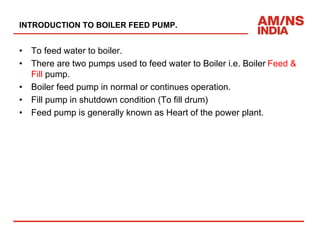
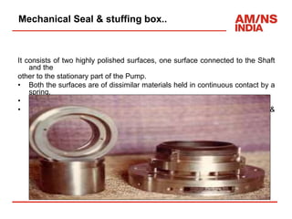
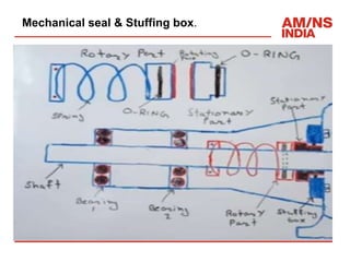
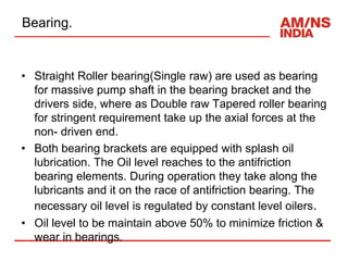
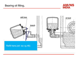
By: Iyyappan. D
1
Presentation on
BOILER FEED PUMP Operation &
Trouble Shooting
Contents.
• Introduction of BFP
• Technical Specification.
• GA & Cross-sectional view of BFP.
• Working principle of BFP.
• NPSH(Net Positive suction Head)
• Vapor pressure & Cavitation.
• Balancing drum & Balance leak off line .
• Minimum Recirculation.
• Mechanical Seal & Stuffing box.
• Bearings.
• Inter lock & Protection.
INTRODUCTION TO BOILER FEED PUMP.
• To feed water to boiler.
• There are two pumps used to feed water to Boiler i.e. Boiler Feed &
Fill pump.
• Boiler feed pump in normal or continues operation.
• Fill pump in shutdown condition (To fill drum)
• Feed pump is generally known as Heart of the power plant.
Technical Specification.
DESCRIPTION Unit-1 BFP 1A/ 1B unit-2 BFP 2A/2B
MAKE/TYPE
SULZER PUMPS INDIA
LTD.
SULZER PUMPS INDIA
LTD.
NO OF STAGE 10 & 9 9 & 10
SPEED (rpm) 2972 2972
SUC/DISC
PRESSURE(kg/cm2)
1.72/86.89, 1.73/78.28 1.74/79.36 , 1.73/86
BLO PRESSURE(kg/cm2)
3.24/3.3 2.9/2.5
HEAD/FLOW
( mwc / m3/hr )
952/163 952/163
CURRENT RATED- 63 AMP.
CURRENT TAKEN
(Amp/Amp)
50AMP/ 45AMP 45AMP/ 50AMP
POWER CONSUMTION (Kw) 615 615
BFP Cross sectional View
GA of BFP
Working principle.
Diffuser
High velocity
water IN, with low
inlet pressure
Water OUT with high
pressure
Net positive suction head (NPSH).
• It is total pressure at the suction of the pump over &
above vapor pressure at pumping temperature which is
necessary to avoid vaporization and cavitation of the 1st
stage of Impellers eye.
• NPSH can be increased by lowering the pump platform.
Vapor pressure & Cavitation.
• When Vaporization takes place, the molecules escapes from free
surface of liquid. These molecules get accumulated in the space
between the free liquid surface and top of the vessel. These
accumulated vapors exerts a pressure on the liquid surface. This
pressure is known as Vapor pressure of liquid .
• Cavitation is the phenomenon of formation of vapor bubbles of a
flowing liquid in a region where the pressure of the liquid fall below
the vapor pressure and sudden collapsing of these vapour bubbles
in a region of higher pressure.
• When vapour bubble collapse, a very high pressure is created which
causes pitting action on the surface and then cavities formed on
metallic surface.
Balancing Drum.
• During the operation an axial thrust is exerted on rotor towards the
suction side.
• The forces per stages are cumulative and considerable axial load
result. These forces are absorbed by the hydraulic balance device.
• The balance device consists of balancing drum , which is liner
house in the discharge casing.
• A small portion of the feed water in the order of about 10% which is
not calculated to the guaranteed delivery capacity is taken off from
the space behind the last impeller for the operation of the automatic
balancing device to balance the hydraulic axial thrust of the pump
rotor.
• The purpose of the balancing device is to take up thrust pressure in
a similar way as the thrust bearing
Balancing Leak off Line.
• In multi stage BFP, there exists large pressure difference between
discharge end & suction end. Due to this, thrust acts on the rotor in
the direction of suction of the pump
• This axial thrust will put on Thrust bearing, it may damage. so this is
to balance through BLO line. BLO line is connected from discharge
side to suction side(Deaerator) of the pump.
• Balance leak off line flow is 66.5 to 100lpm.
• A safety valve is provided to release if balance leakoff pressure
goes beyond 5kg/cm2.
Balancing .
Balancing
chamber
AXIAL
THURST
Balancing
Disk
Balance
Leakoff line
Towards pump
NDE side
Axial
Balancing
 Max. permissible
clearance = 0.4-
0.45 mm
Min Recirculation Line.
• At low flow rate pump efficiency reduces & results in
overheating of pump.
• Lowest load permitted on the BFP is of order of 20% of
designed capacity.
• Automatic opening of recirculation valve maintains
minimum flow through the pump.
• MRL taken tapping from BFP discharge line(Before
Discharge isolation valve).
ARC WHY?
• IF ARC line is not available & Discharge main isolation
valve is in close condition:
• Then there is no other flow path avail from the pump ,
The impeller will churn the same volume of water as it
rotates in the pump casing.
• This will increase the temp. of liquid (due to friction) in
the pump casing to the point that it will flash to vapor.
• Excessive heating result pump Catastrophe failure.
ARC valve
Mechanical Seal & stuffing box.
• It is used to prevent leakage of fluid being pumped between rotating
parts and stationary parts or machine elements.
• Working ability of the feed pump increases.
• Cooling of stuffing box space should be perfect by the use of
mechanical seal.
• Cooling is carried out by the circulation of water between the stuffing
box space .
• Coolers are designed to keep the stuffing box space temperature
below 800C.
• Cooling water pressure for Stuffing box & mech seal is 3 to 5
kg/cm2.
• Cooling water flow through each staffing box is 8lpm & through each
gland is 2lpm.
Mechanical Seal & stuffing box..
It consists of two highly polished surfaces, one surface connected to the Shaft
and the
other to the stationary part of the Pump.
• Both the surfaces are of dissimilar materials held in continuous contact by a
spring.
• These wearing surfaces are perpendicular to the axis of Shaft.
• A thin film of working fluid between these faces provides cooling &
lubrication.
Mechanical seal & Stuffing box.
Bearing.
• Straight Roller bearing(Single raw) are used as bearing
for massive pump shaft in the bearing bracket and the
drivers side, where as Double raw Tapered roller bearing
for stringent requirement take up the axial forces at the
non- driven end.
• Both bearing brackets are equipped with splash oil
lubrication. The Oil level reaches to the antifriction
bearing elements. During operation they take along the
lubricants and it on the race of antifriction bearing. The
necessary oil level is regulated by constant level oilers.
• Oil level to be maintain above 50% to minimize friction &
wear in bearings.
Bearing oil filling.
Refill here.(oil- iso vg 46)
Roller Bearing.
• NDE side(Tapered double raw
roller bearing)
• DE side(Straight single raw
roller bearing)
BEARING HOUSINGS
• They house the Bearing at both DE & NDE side.
• These are in the form of cylindrical castings split on the
horizontal Shaft axis, located one each at DE & NDE
sides of the Pump.
Starting Permissive & Stop
interlock
BFP Protections(Tripping
parameters)
• Deaerator level should not be very low i: e 3 %( water at
deaerator level).
• Motor should not be overload, i: e motor rated current is
63Amps.
• Pump bearing temp at DE(105degc) & NDE (105degc).
• Motor bearing temp at DE(105degc) & NDE (105degc).
• Motor winding R, Y, B winding temp at 120degc.
• BFP suction DP at 1600mmwc.
• LPBS operated & Feeder OFF.
• If Running BFP will trip by any of the above cause then
Standby BFP will start/pickup.
THANK YOU
25

Boiler feed pump operation.pptx

  • 1.
    By: Iyyappan. D 1 Presentationon BOILER FEED PUMP Operation & Trouble Shooting
  • 2.
    Contents. • Introduction ofBFP • Technical Specification. • GA & Cross-sectional view of BFP. • Working principle of BFP. • NPSH(Net Positive suction Head) • Vapor pressure & Cavitation. • Balancing drum & Balance leak off line . • Minimum Recirculation. • Mechanical Seal & Stuffing box. • Bearings. • Inter lock & Protection.
  • 3.
    INTRODUCTION TO BOILERFEED PUMP. • To feed water to boiler. • There are two pumps used to feed water to Boiler i.e. Boiler Feed & Fill pump. • Boiler feed pump in normal or continues operation. • Fill pump in shutdown condition (To fill drum) • Feed pump is generally known as Heart of the power plant.
  • 4.
    Technical Specification. DESCRIPTION Unit-1BFP 1A/ 1B unit-2 BFP 2A/2B MAKE/TYPE SULZER PUMPS INDIA LTD. SULZER PUMPS INDIA LTD. NO OF STAGE 10 & 9 9 & 10 SPEED (rpm) 2972 2972 SUC/DISC PRESSURE(kg/cm2) 1.72/86.89, 1.73/78.28 1.74/79.36 , 1.73/86 BLO PRESSURE(kg/cm2) 3.24/3.3 2.9/2.5 HEAD/FLOW ( mwc / m3/hr ) 952/163 952/163 CURRENT RATED- 63 AMP. CURRENT TAKEN (Amp/Amp) 50AMP/ 45AMP 45AMP/ 50AMP POWER CONSUMTION (Kw) 615 615
  • 5.
  • 6.
  • 7.
    Working principle. Diffuser High velocity waterIN, with low inlet pressure Water OUT with high pressure
  • 8.
    Net positive suctionhead (NPSH). • It is total pressure at the suction of the pump over & above vapor pressure at pumping temperature which is necessary to avoid vaporization and cavitation of the 1st stage of Impellers eye. • NPSH can be increased by lowering the pump platform.
  • 9.
    Vapor pressure &Cavitation. • When Vaporization takes place, the molecules escapes from free surface of liquid. These molecules get accumulated in the space between the free liquid surface and top of the vessel. These accumulated vapors exerts a pressure on the liquid surface. This pressure is known as Vapor pressure of liquid . • Cavitation is the phenomenon of formation of vapor bubbles of a flowing liquid in a region where the pressure of the liquid fall below the vapor pressure and sudden collapsing of these vapour bubbles in a region of higher pressure. • When vapour bubble collapse, a very high pressure is created which causes pitting action on the surface and then cavities formed on metallic surface.
  • 10.
    Balancing Drum. • Duringthe operation an axial thrust is exerted on rotor towards the suction side. • The forces per stages are cumulative and considerable axial load result. These forces are absorbed by the hydraulic balance device. • The balance device consists of balancing drum , which is liner house in the discharge casing. • A small portion of the feed water in the order of about 10% which is not calculated to the guaranteed delivery capacity is taken off from the space behind the last impeller for the operation of the automatic balancing device to balance the hydraulic axial thrust of the pump rotor. • The purpose of the balancing device is to take up thrust pressure in a similar way as the thrust bearing
  • 11.
    Balancing Leak offLine. • In multi stage BFP, there exists large pressure difference between discharge end & suction end. Due to this, thrust acts on the rotor in the direction of suction of the pump • This axial thrust will put on Thrust bearing, it may damage. so this is to balance through BLO line. BLO line is connected from discharge side to suction side(Deaerator) of the pump. • Balance leak off line flow is 66.5 to 100lpm. • A safety valve is provided to release if balance leakoff pressure goes beyond 5kg/cm2.
  • 12.
    Balancing . Balancing chamber AXIAL THURST Balancing Disk Balance Leakoff line Towardspump NDE side Axial Balancing  Max. permissible clearance = 0.4- 0.45 mm
  • 13.
    Min Recirculation Line. •At low flow rate pump efficiency reduces & results in overheating of pump. • Lowest load permitted on the BFP is of order of 20% of designed capacity. • Automatic opening of recirculation valve maintains minimum flow through the pump. • MRL taken tapping from BFP discharge line(Before Discharge isolation valve).
  • 14.
    ARC WHY? • IFARC line is not available & Discharge main isolation valve is in close condition: • Then there is no other flow path avail from the pump , The impeller will churn the same volume of water as it rotates in the pump casing. • This will increase the temp. of liquid (due to friction) in the pump casing to the point that it will flash to vapor. • Excessive heating result pump Catastrophe failure.
  • 15.
  • 16.
    Mechanical Seal &stuffing box. • It is used to prevent leakage of fluid being pumped between rotating parts and stationary parts or machine elements. • Working ability of the feed pump increases. • Cooling of stuffing box space should be perfect by the use of mechanical seal. • Cooling is carried out by the circulation of water between the stuffing box space . • Coolers are designed to keep the stuffing box space temperature below 800C. • Cooling water pressure for Stuffing box & mech seal is 3 to 5 kg/cm2. • Cooling water flow through each staffing box is 8lpm & through each gland is 2lpm.
  • 17.
    Mechanical Seal &stuffing box.. It consists of two highly polished surfaces, one surface connected to the Shaft and the other to the stationary part of the Pump. • Both the surfaces are of dissimilar materials held in continuous contact by a spring. • These wearing surfaces are perpendicular to the axis of Shaft. • A thin film of working fluid between these faces provides cooling & lubrication.
  • 18.
    Mechanical seal &Stuffing box.
  • 19.
    Bearing. • Straight Rollerbearing(Single raw) are used as bearing for massive pump shaft in the bearing bracket and the drivers side, where as Double raw Tapered roller bearing for stringent requirement take up the axial forces at the non- driven end. • Both bearing brackets are equipped with splash oil lubrication. The Oil level reaches to the antifriction bearing elements. During operation they take along the lubricants and it on the race of antifriction bearing. The necessary oil level is regulated by constant level oilers. • Oil level to be maintain above 50% to minimize friction & wear in bearings.
  • 20.
    Bearing oil filling. Refillhere.(oil- iso vg 46) Refill here.(oil- iso vg 46)
  • 21.
    Roller Bearing. • NDEside(Tapered double raw roller bearing) • DE side(Straight single raw roller bearing)
  • 22.
    BEARING HOUSINGS • Theyhouse the Bearing at both DE & NDE side. • These are in the form of cylindrical castings split on the horizontal Shaft axis, located one each at DE & NDE sides of the Pump.
  • 23.
    Starting Permissive &Stop interlock
  • 24.
    BFP Protections(Tripping parameters) • Deaeratorlevel should not be very low i: e 3 %( water at deaerator level). • Motor should not be overload, i: e motor rated current is 63Amps. • Pump bearing temp at DE(105degc) & NDE (105degc). • Motor bearing temp at DE(105degc) & NDE (105degc). • Motor winding R, Y, B winding temp at 120degc. • BFP suction DP at 1600mmwc. • LPBS operated & Feeder OFF. • If Running BFP will trip by any of the above cause then Standby BFP will start/pickup.
  • 25.