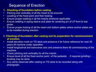
1. Checking offoundation before casting.
• Pitching and verticality of all the Insert to be ensured
• Leveling of the fixed point and their locking.
• Ensure proper welding in all the inserts wherever applicable.
• Ensure welding in piping sleeve and plate for centering pin of LP front & rear
girder.
• Ensure proper locking of all the insert and bottom plates where anchor plates are
to be installed during erection.
2. Checking of foundation after casting and its preparation for commencement
of erection.
• Install elevation mark on TG deck and preserve it for future reference for next 30
years till machine under operation.
• Install longitudinal and transverse axis and preserve them till commissioning of the
machine.
• Check pitching and verticality for all the inserts .
• Ensure level of all the fixed anchor point of the pedestal. , if required grinding /
leveling may be done.
• Any cavity observed after casting on TG deck to be recorded along with
photograph.
Sequence of Erection
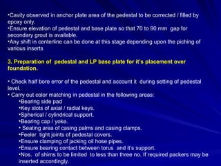
3.
•Cavity observed inanchor plate area of the pedestal to be corrected / filled by
epoxy only.
•Ensure elevation of pedestal and base plate so that 70 to 90 mm gap for
secondary grout is available.
•Any shift in centerline can be done at this stage depending upon the piching of
various inserts
3. Preparation of pedestal and LP base plate for it’s placement over
foundation.
• Check half bore error of the pedestal and account it during setting of pedestal
level.
• Carry out color matching in pedestal in the following areas:
•Bearing side pad
•Key slots of axial / radial keys.
•Spherical / cylindrical support.
•Bearing cap / yoke.
• Seating area of casing palms and casing clamps.
•Feeler tight joints of pedestal covers.
•Ensure clamping of jacking oil hose pipes.
•Ensure bearing contact between torus and it’s support.
•Nos. of shims to be limited to less than three no. If required packers may be
inserted accordingly.
4.
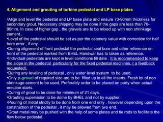
4. Alignment andgrouting of turbine pedestal and LP base plates
•Align and level the pedestal and LP base plate and ensure 70-90mm thickness for
secondary grout. Necessary chipping may be done if the gaps are less than 70-
90mm. In case of higher gap , the gravels are to be mixed up with non shrinkage
cement .
•Level of the pedestal should be set as per the catenery value with correction for half
bore error , if any.
•During alignment of front pedestal the pedestal seal bore and other reference on
front of the pedestal marked from BHEL Haridwar has to taken as reference.
•Individual pedestals are kept in level conditions till date . It is recommended to keep
the slope in the pedestal particularly for the fixed pedestal machines. ( a feedback
requested).
•During any leveling of pedestal , only water level system to be used.
•Only p-gravel of required size are to be filled up in all the inserts. Fresh lot of non
shrinkage cement to be used. Preferably order to be placed on party when actual
erection starts.
•Curing of grout to be done for minimum of 21 days.
•Grouting supervision to be dome by BHEL and not by supplier.
•Pouring of metal strictly to be done from one end only , however depending upon the
construction of the pedestal , it may be allowed from two end.
•Grout metal may be pushed with the help of some plates and tie rods to facilitate the
flow below pedestal.
5.
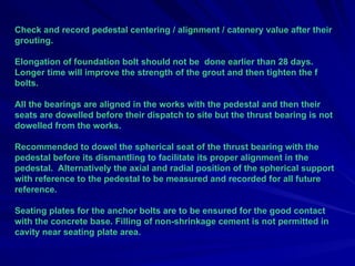
Check and recordpedestal centering / alignment / catenery value after their
grouting.
Elongation of foundation bolt should not be done earlier than 28 days.
Longer time will improve the strength of the grout and then tighten the f
bolts.
All the bearings are aligned in the works with the pedestal and then their
seats are dowelled before their dispatch to site but the thrust bearing is not
dowelled from the works.
Recommended to dowel the spherical seat of the thrust bearing with the
pedestal before its dismantling to facilitate its proper alignment in the
pedestal. Alternatively the axial and radial position of the spherical support
with reference to the pedestal to be measured and recorded for all future
reference.
Seating plates for the anchor bolts are to be ensured for the good contact
with the concrete base. Filling of non-shrinkage cement is not permitted in
cavity near seating plate area.
6.
5. Preparation andplacement of HP module over foundation.
•Carry out color matching in various key slots and palm packers area of the casing.
•Check/ correct rotor coupling faces for concavity / convexity Any correction , if
required, to be done before installation of module in position.
•Place and provisionally align HP module without removing the transport device.
Ensure parallity of radial and axial key slot of the casing with pedestal. Incase of
variation , the module may be removed and slots are to be corrected for its
parallality.
•Place / install HP module first .
•Check / Record run out of journal & coupling faces .
•Check and compare roll check and bump check value of the HP module with MU
value.
6. Place /install IP module after completing checks for HP module..
•Carry out similar checks as mentioned for HP module.
• IP rotor face run out to be checked with one side on lifting tackle.
•The bump test vale may be checked at a later stage during coupling with HP rotor.
7.
7. Alignment ofHP / IP / LP rotors.
•Align the rotors maintaining pedestal seal bore and it’s catenery. To facilitate it is
recommended to maintain initially the catenery on journal 3 & 4. Any variation / error
in seal bore reading for various rotors are to be distributed . Measurement of
catenery are to be done with height measuring blocks and water level jar.
•During alignment of rotors bearing side pads are to be kept loose or side pads may
not be fitted.
•Always install upper half of the bearing in position to avoid entry of dust and foreign
material. For any oiling on journal , the upper half bearing may be removed and put
back immediately after pouring of oil. Preferably use oil better than grade 180.
The oil can also be given in the bearing through jacking oil hose pipe with the help of
a hydraulic pump used for hydraulic jack. This will avoid removal of bearing every
time for pouring of oil.
•The alignment of bearing with respect to rotor is to be ensured before rotation of the
rotor
•Ensure SOC of the bearing when rotor is just loaded on the bearing . Any correction
in alignment of the bearing for achieving the SOC is possible till rotor is not rotated
on the bearing. The correction is to be done by rotating/tilting the cylindrical support
of the bearing.
•Slip gauge to be used for alignment of the rotor in place of feeler gauge.
•HP-IP , LP-IP rotors to be aligned without coupling of any of the rotor together.
8.
•Align and positionHP/IP/LP rotor as per their face measurement .
•Do not rotate rotor with barring gear teeth.
•Always use periphery hole for rotation of the rotor.
•Adjustment between torus and bearing body is permitted to a value of 0.35 mm in
the Left/ Right and un/down side during lifetime of the bearing. This adjustment
preferably Should be left for subsequent overhauling of the machine.
•Any adjustment in left/right direction for more than +/- 0.1mm may be done by
shifting the cylindrical support of the bearing. The height adjustment can be done
By adjusting shims below the cylindrical support.
•Please note that FIXED PEDESTAL machines requires more accuracy during
erection process compared to SLIDING PEDESTAL machines.
9.
8. Coupling ofHP / IP / LP rotors.
•Ensure that the rotor coupling faces are matched as per the face run out value.
Two numbers centering pin to be used during alignment of coupling holes .
First couple HP-IP rotor and ensure CRO and swing check preferably by using
SWING CHECK DEVICE.
•Full set of temporary bolts to be used and tightened to design elongation at this
stage.
•Indifferent tightening of bolts for achieving of swing check and CRO is not
permitted.
•Couple LP/IP rotor and ensure CRO on LP/IP coupling . Full set of clearance
bolts with design elongation to be fitted.
•Recheck CRO on HP/IP coupling and swing check after coupling of LP/IP rotor.
Any variation on CRO of HP/IP coupling and swing check is not permitted. It is
expected that HP/IP coupling and swing check is not influenced by coupling of LP
rotor.
•Any variation on CRO of HP/IP/LP coupling and swing check to be corrected
by interchanging hole position of the rotor at initial stage. In case the value are not
achieved , then the necessary correction on coupling faces are to be carried out
before reaming / honing of the coupling.
10.
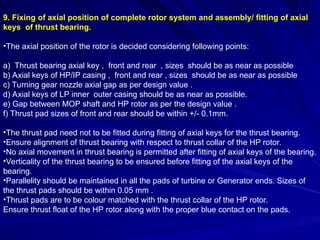
9. Fixing ofaxial position of complete rotor system and assembly/ fitting of axial
keys of thrust bearing.
•The axial position of the rotor is decided considering following points:
a) Thrust bearing axial key , front and rear , sizes should be as near as possible
b) Axial keys of HP/IP casing , front and rear , sizes should be as near as possible
c) Turning gear nozzle axial gap as per design value .
d) Axial keys of LP inner outer casing should be as near as possible.
e) Gap between MOP shaft and HP rotor as per the design value .
f) Thrust pad sizes of front and rear should be within +/- 0.1mm.
•The thrust pad need not to be fitted during fitting of axial keys for the thrust bearing.
•Ensure alignment of thrust bearing with respect to thrust collar of the HP rotor.
•No axial movement in thrust bearing is permitted after fitting of axial keys of the bearing.
•Verticality of the thrust bearing to be ensured before fitting of the axial keys of the
bearing.
•Parallelity should be maintained in all the pads of turbine or Generator ends. Sizes of
the thrust pads should be within 0.05 mm .
•Thrust pads are to be colour matched with the thrust collar of the HP rotor.
Ensure thrust float of the HP rotor along with the proper blue contact on the pads.
11.
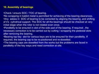
10. Assembly ofbearings
•Check / ensure SOC / TOC of bearing.
•No scrapping in babbit metal is permitted for achieving of the bearing clearances.
•Any askew in SOC of bearing to be corrected by aligning the bearing .and shifting
of it’s cylindrical support. The SOC for all the bearings should be checked at very
initial stage when the rotor is not rotated even once.
•Parallelity to be ensured in slot of the side pad of the bearing. If required , the
necessary correction is to be carried out by cutting / scrapping the pedestal slots
after removing the bearing.
•Bearing top key slot for various keys are to be ensured for their parallelity. If
required, the bearing cap to be re-positioned and re-dowelled.
•The bearing caps are dowelled from the works but the problems are faced in
parallelity of the key ways and need correction at site.
12.
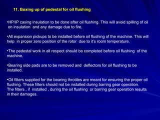
11. Boxing upof pedestal for oil flushing
•HP/IP casing insulation to be done after oil flushing. This will avoid spilling of oil
on insulation and any damage due to fire.
•All expansion pickups to be installed before oil flushing of the machine. This will
help in proper zero position of the rotor due to it’s room temperature.
•The pedestal work in all respect should be completed before oil flushing of the
machine.
•Bearing side pads are to be removed and deflectors for oil flushing to be
installed.
•Oil filters supplied for the bearing throttles are meant for ensuring the proper oil
flushing. These filters should not be installed during barring gear operation.
The filters , if installed , during the oil flushing or barring gear operation results
in their damages.
13.
12. Assembly ofLP casing
•Assembly of guarder and end wall can be done immediately after completion of LP base
plate grouting.
•Inner casing to be installed when all major components of the condenser are
positioned.
•Carry out color matching in all machined area of the LP guarder and end wall.
•Check/ensure parallity of the key slot of the end wall.
•Leveling & alignment of LP guarder & the end wall after their assembly. LP casing
level to be maintained as per the catenery of the machine.
•Radial alignment of LP casing to be done with piano wire and axial alignment with
respect to bearing centerline i.e. bearing no: 3 & 4.
•Assemble final radial / axial keys of the casing.
14.
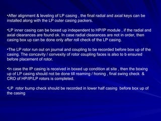
•After alignment &leveling of LP casing , the final radial and axial keys can be
installed along with the LP outer casing packers.
•LP inner casing can be boxed up independent to HP/IP module , if the radial and
axial clearances are found ok. In case radial clearances are not in order, then
casing box up can be done only after roll check of the LP casing.
•The LP rotor run out on journal and coupling to be recorded before box up of the
casing. The concavity / convexity of rotor coupling faces is also to b ensured
before placement of rotor.
•In case the IP casing is received in boxed up condition at site , then the boxing
up of LP casing should not be done till reaming / honing , final swing check &
CRO of HP/IP/LP rotors is completed.
•LP rotor bump check should be recorded in lower half casing before box up of
the casing
15.
13. HORN DROPcheck of HP-IP Casing.
•Horn drop check of the casing to be made without connection of any pipelines
with the casing.
•During making of horn drop the casing radial keys should not be installed and
rotor should be free inside the casing.
•Horn drop values should be made within 0.05 / 0.10 mm in left / right direction.
Any variation in horn drop values after connection of pipelines may be left as it is
till positive loading on the casing palm is observed.
•No correction in horn drop values can be done by adjusting the height of the
packers.
•Correction of horn drop value can only be done by identifying the defective
pipeline and subsequent cutting/re-welding.
Sequence of overhaulingactivities
• Stoppage of barring gear and oil system.
• Removal of HP/IP casing insulation after stoppage of oil circulation.
•Opening pedestal cover and upper half bearings.
•Measurement of bearing clearances.
•Measurement of catenery over the journal of the turbine rotors.
•De-coupling of LP/Gen rotors.
•Swing check measurement on HPF end of the rotor.
•Recording of CRO of the HP/IP and IP/LP coupling.
•Bump check of HP/IP casing.
•De-coupling of HP/IP/LP rotors. Horn drop check of HP/IP casing. If no loading
is observed on any of the palm of the casing , then it needs correction.
•Necessary corrections based on Horn Drop values to be done by cutting / re-
welding of pipelines , and not by adjusting the thickness of the packer.
18.
•Check / Recordmis-match of the HP inlet / exhaust pipe line before lifting of
module for future reference.
•Removal of HP module for overhaul.
•Dummy shaft to be used during overhaul of HP module. In absence of dummy shaft
the position of casing centering between HP inner/outer is not known.
•Checking of bearing contact between torus and its support and replacement of
bearing , if required.
•Checking of pedestal level as per the centenary value and level of individual
pedestal. Necessary correction in pedestal level is to be carried out , if these are
sliding pedestal.
•Checking of pedestal centering with respect to piano wire.
•Checking of pedestal packers for their contact.
•Replacement of bearing with piano wire in place of directly with rotor.
•Checking/correction concavity/convexity of rotor couplings.
•Re-finning of HP/IP rotor & casing as required.
•Coupling of HP/IP rotor to be done first and record swing check and CRO.
Afterwards IP/LP rotor to be coupled.
•No change in CRO and swing check of HP/IP rotor is permitted with the coupling of
IP/LP rotor.
19.
Specific observation duringCOH of machine
which needs special attention
a) Sinking of pedestal no:3 by around 3 mm for more than 10 years old
machine. This has resulted in reverse catenery of the machine.
b) Steam leakage through HP/IP casing glands . No efforts are made for re-
finning of rotor / casing.
c) Bearing no: 3 & 4 needs replacement after each 3-4 years due to widen
contact in torus.
d) Pitting in thrust bearing axial keys.
e) Damage in lubrite packer of the HP/IP casing in fixed pedestal machine.
f) Higher IP differential expansion in positive direction
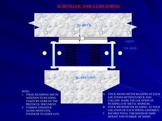
SCHEMATIC FOR GERBSPRING
TIE ROD
SHIM
TG DECK
TG COLUMN
NOTE:
1. THESE READINGS ARE IN
ADDITION TO READING
TAKEN BY GERB ON THE
PROTOCOL DOCUMENT.
2 TURBINE ENGINEER
ALONG WITH CIVIL
ENGINEER TO ASSOCIATE.
A. STICK MICRO METER READING AT FOUR
LOCATIONS BETWEEN DECK AND
COLUMN. MARK THE LOCATION OF
READING (USE METAL MARKER).
B. STICK MICROMETER READING AT FOUR
LOCATION OF EACH SPRING ASSEMBLY.
C RECORD TOTAL THICKNESS OF SHIM
HEIGHT AND NUMBER OF SHIMS.
A A
B B
C