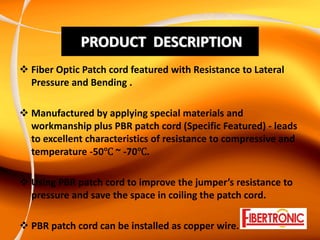
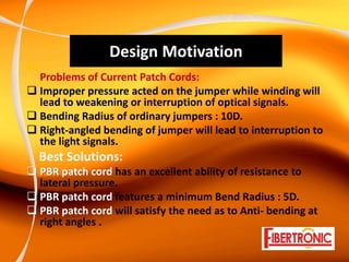
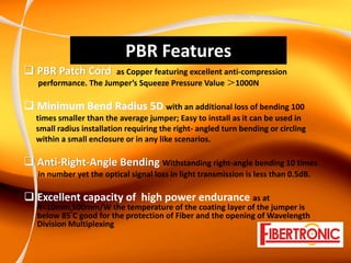
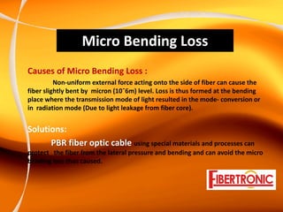
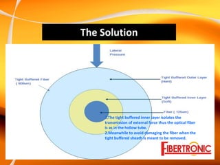
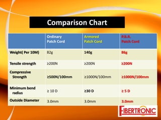
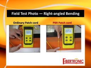
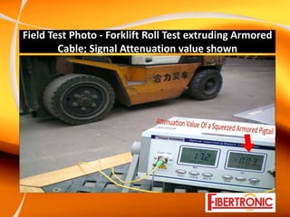
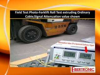
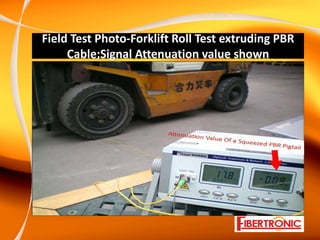
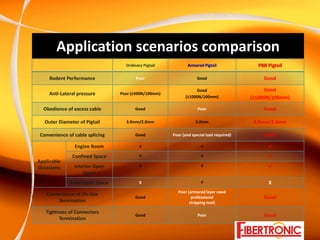
P.B.R. Patch Cord
Rodent Proof Fiber Optical Cable

A New Born Star for the Utility Room

Designed for the last ten meter in optical network FTTH

Patent No. ZL 2010 2 0137340.6
PRODUCT  DESCRIPTION
Fiber Optic Patch cord featured with Resistance to Lateral 
Pressure and Bending .

Manufactured by applying special materials and 
workmanship plus PBR patch cord (Specific Featured) ‐ leads 
to excellent characteristics of resistance to compressive and 
temperature ‐50 ~ ‐70 .

Using PBR patch cord to improve the jumper’s resistance to 
pressure and save the space in coiling the patch cord.

PBR patch cord can be installed as copper wire.
Design Motivation
Exi
      Problems of Current Patch Cords:
      Improper pressure acted on the jumper while winding will 
      lead to weakening or interruption of optical signals.
      Bending Radius of ordinary jumpers : 10D.
      Right‐angled bending of jumper will lead to interruption to 
      the light signals.
      Best Solutions:
      PBR patch cord has an excellent ability of resistance to 
      lateral pressure. 
      PBR patch cord features a minimum Bend Radius : 5D.
      PBR patch cord will satisfy the need as to Anti‐ bending at 
      right angles .
PBR Features
PBR Patch Cord      as Copper featuring excellent anti‐compression  
performance. The Jumper’s Squeeze Pressure Value >1000N

Minimum Bend Radius 5D with an additional loss of bending 100 
times smaller than the average jumper; Easy to install as it can be used in  
small radius installation requiring the right‐ angled turn bending or circling  
within a small enclosure or in any like scenarios.

Anti‐Right‐Angle Bending Withstanding right‐angle bending 10 times 
in number yet the optical signal loss in light transmission is less than 0.5dB.

Excellent capacity of  high power endurance as at 
R<10mm,500mm/W the temperature of the coating layer of the jumper is 
below 85°C good for the protection of Fiber and the opening of Wavelength 
Division Multiplexing 
Micro Bending Loss
Causes of Micro Bending Loss : 
          Non‐uniform external force acting onto the side of fiber can cause the 
fiber slightly bent by  micron (10ˉ6m) level. Loss is thus formed at the bending 
place where the transmission mode of light resulted in the mode‐ conversion or 
in  radiation mode (Due to light leakage from fiber core).


Solutions:
      PBR fiber optic cable using special materials and processes can 
protect   the fiber from the lateral pressure and bending and can avoid the micro 
bending loss thus caused.
The Solution


     1.The tight buffered inner layer isolates the 
     transmission of external force thus the optical fiber 
     is as in the hollow tube. 
     2.Meanwhile to avoid damaging the fiber when the 
     tight buffered sheath is meant to be removed. 
Comparison Chart
                    Ordinary      Armored        P.B.R.
                    Patch Cord    Patch Cord     Patch Cord

Weight( Per 10M)    82g           140g           86g

Tensile strength    ≥200N         ≥200N          ≥200N

Compressive
 Strength           ≥500N/100mm   ≥1000N/100mm   ≥1000N/100mm

Minimum bend
 radius             ≥ 10 D        ≥30 D          ≥ 5 D

Outside Diameter    3.0mm         3.0mm          3.0mm
Field Test Photos – Bending Wound
   Ordinary Patch cord                                  PBR Patch cord
Field Test Photo — Right‐angled Bending

Ordinary Patch cord    PBR Patch cord
Field Test Photo ‐ Forklift Roll Test extruding Armored 
        Cable; Signal Attenuation value shown
Field Test Photo‐Forklift Roll Test extruding Ordinary 
        Cable;Signal Attenuation value shown
Field Test Photo‐Forklift Roll Test extruding PBR 
     Cable;Signal Attenuation value shown
Application scenarios comparison
                                    Ordinary Pigtail            Armored Pigtail               PBR Pigtail 

     Rodent Performance                  Poor                        Good                        Good 

                                                                    Good                         Good
     Anti‐Lateral pressure        Poor (≥500N/100mm) 
                                                               (≥1000N/100mm)               (≥1000N/100mm) 

  Obedience of excess cable              Good                        Poor                        Good

   Outer Diameter of Pigtail        3.0mm/2.0mm                     3.0mm                    3.0mm/2.0mm

 Convenience of cable splicing           Good           Poor (and special tool required)         Good 

                Engine Room                √                           √                           √
               Confined Space              √                           √                           √
Applicable 
                Interior Open              √                           √                           √
Occasions 
                    Space 
              Field Open Space             X                           √                           X
                                                           Poor (armored layer need 
    Convenience of On‐Site 
                                         Good                     professional                   Good 
         Termination                                             stripping tool) 

   Tightness of Connectors 
                                         Good                        Poor                        Good 
         Termination 
Application Showcase
Before Adjustment   After Adjustment
Application Showcase
Adjusted Cable Spool Tray               Field Site Custom Fixed‐Length
                                                  FC Connectivity
Application Showcase
Original Groove Cabling    After sheaved Cabling
40G WDM Operational Under Fiber Bending 
 (Network Field : Guang Dong Province in China)
The field test performed against the Anti‐microbend pigtail curled with 5 tiny circling 
and of a bend diameter 1.5cm each , the signal performance data observed there‐after 
is as follows:

Optical power with the optical power input of ‐9.1dbm, the result shows that there’s an 
increase in attenuation of 0.2dbm compared with what observed before the bending of the pigtail.

BER Performance        Before test, the Bit Error Correction was 9, which is at the level of 10^9 .

Dispersion Properties The result shows that Dispersion Compensation value is 10ps/nm.
Compared to before bending, the amount of dispersion compensation increased only by
20ps/nm, which is still within the normal range.


Conclusion
Based on the result of from this Application test against a 40G Wavelength Division
system, there’s only small differences on performance before and after adding an Anti‐
microbending pigtail onto the WDM.  Also, the optical power and dispersion are in the 
normal range as expected.  While the BER Performance varies within the range of 10^9 
~ 10^10, it still meets with the normal operation demand. With the superiority of the 
anti‐bend and resistance to bend, the Anti‐microbending pigtail still fulfils the 40G high‐
speed wavelength division system performance requirements while providing more 
advantage by taking up less space and smaller footprints.  

***P.B.R. Patch Cord***