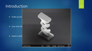
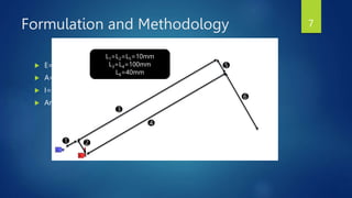
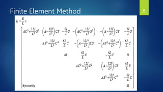
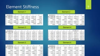
Pantograph
Mechanism
FEM SEMESTER PROJECT
PRESENTER: JAWAD ZAKIR
REGISTRATION ID: 195100 MS AE F-19
1
Introduction
 Scale up and down
 Low cost mechanism
 Used in both micro and macro level
2
Literature Review
 Manipulator design in robots [1]
 1 DOF pantograph leg mechanism for the kinematics of machine keeping in
view the idea of low cost and easy operation idea [2]
[2] Operation Analysis of a One-DOF Pantograph Leg Mechanisms (Proceedings of the RAAD 2008 17th International
Workshop on Robotics in Alpe-Adria-Danube Region September 15-17, 2008, Ancona, Italy)
[1]Yang, D. C. H., and Y. Y. Lin. “Pantograph Mechanism as a Non-Traditional Manipulator Structure.” Mechanism and
Machine Theory, vol. 20, no. 2, Jan. 1985, pp. 115–22
3
Literature Review
 Manipulator design in robots [1]
 1 DOF pantograph leg mechanism for the kinematics of machine keeping in
view the idea of low cost and easy operation idea [2]
 Thermal erosion
 Complaint mechanism
[2] Operation Analysis of a One-DOF Pantograph Leg Mechanisms (Proceedings of the RAAD 2008 17th International
Workshop on Robotics in Alpe-Adria-Danube Region September 15-17, 2008, Ancona, Italy)
[1]Yang, D. C. H., and Y. Y. Lin. “Pantograph Mechanism as a Non-Traditional Manipulator Structure.” Mechanism and
Machine Theory, vol. 20, no. 2, Jan. 1985, pp. 115–22
4
Objective
 Design a mechanism
 Observe the magnitude of increase in initial value
 Compare the data of MATLAB ® with the ANSYS ® Static Structural
5
Problem Statement
 Design a mechanism that can increase the initial displacement using a
simple pantograph mechanism. Provide a solution using analytic
calculation and compare the data with any commercially available
software. Also, explain the application of this system in industry.
6
Formulation and Methodology
 E=2e+11 Pa (structural Steel)
 A=1e-8 m2
 I=8.33e-18 m4
 Angle with global axis is 300
1 2
3
4
5
6
L1=L2=L5=10mm
L3=L4=100mm
L6=40mm
7
Finite Element Method
 Direct Force Displacement Method(DFDM)
 Beam element has been used
 Stiffness matrix is calculated
8
Element Stiffness
Element 1 Element 2
Element 3 Element 4
Element 5 Element 6
9
Global Stiffness Matrix
 K_Global
10
Displacements
 Displacements at each node
 x and y displacements are in meters
2
3
4
5
6
Node
11
Ansys Static Structural
 Mesh element size was 0.01mm and this was forced to maintained
throughout
Working Directory Meshing
12
Ansys Static Structural Results
y-axis Deformation
13
Ansys Static Structural Results Cont.
x-axis Deformation
14
Comparison
Sr No. Parameter ANSYS @ 1N Force MATLAB @1 N Force
1 Amplification 12 8
2 Displacement (mm) 0.739 0.551
15
Conclusion
 Comparison with both analytical and ANSYS
 An amplification is achieved
 Simple cost effective method
 Industry usage (automotive, sensors, or medical industry etcetera)
16

Pantograph Mechanism.pptx

  • 1.
    Pantograph Mechanism FEM SEMESTER PROJECT PRESENTER:JAWAD ZAKIR REGISTRATION ID: 195100 MS AE F-19 1
  • 2.
    Introduction  Scale upand down  Low cost mechanism  Used in both micro and macro level 2
  • 3.
    Literature Review  Manipulatordesign in robots [1]  1 DOF pantograph leg mechanism for the kinematics of machine keeping in view the idea of low cost and easy operation idea [2] [2] Operation Analysis of a One-DOF Pantograph Leg Mechanisms (Proceedings of the RAAD 2008 17th International Workshop on Robotics in Alpe-Adria-Danube Region September 15-17, 2008, Ancona, Italy) [1]Yang, D. C. H., and Y. Y. Lin. “Pantograph Mechanism as a Non-Traditional Manipulator Structure.” Mechanism and Machine Theory, vol. 20, no. 2, Jan. 1985, pp. 115–22 3
  • 4.
    Literature Review  Manipulatordesign in robots [1]  1 DOF pantograph leg mechanism for the kinematics of machine keeping in view the idea of low cost and easy operation idea [2]  Thermal erosion  Complaint mechanism [2] Operation Analysis of a One-DOF Pantograph Leg Mechanisms (Proceedings of the RAAD 2008 17th International Workshop on Robotics in Alpe-Adria-Danube Region September 15-17, 2008, Ancona, Italy) [1]Yang, D. C. H., and Y. Y. Lin. “Pantograph Mechanism as a Non-Traditional Manipulator Structure.” Mechanism and Machine Theory, vol. 20, no. 2, Jan. 1985, pp. 115–22 4
  • 5.
    Objective  Design amechanism  Observe the magnitude of increase in initial value  Compare the data of MATLAB ® with the ANSYS ® Static Structural 5
  • 6.
    Problem Statement  Designa mechanism that can increase the initial displacement using a simple pantograph mechanism. Provide a solution using analytic calculation and compare the data with any commercially available software. Also, explain the application of this system in industry. 6
  • 7.
    Formulation and Methodology E=2e+11 Pa (structural Steel)  A=1e-8 m2  I=8.33e-18 m4  Angle with global axis is 300 1 2 3 4 5 6 L1=L2=L5=10mm L3=L4=100mm L6=40mm 7
  • 8.
    Finite Element Method Direct Force Displacement Method(DFDM)  Beam element has been used  Stiffness matrix is calculated 8
  • 9.
    Element Stiffness Element 1Element 2 Element 3 Element 4 Element 5 Element 6 9
  • 10.
  • 11.
    Displacements  Displacements ateach node  x and y displacements are in meters 2 3 4 5 6 Node 11
  • 12.
    Ansys Static Structural Mesh element size was 0.01mm and this was forced to maintained throughout Working Directory Meshing 12
  • 13.
    Ansys Static StructuralResults y-axis Deformation 13
  • 14.
    Ansys Static StructuralResults Cont. x-axis Deformation 14
  • 15.
    Comparison Sr No. ParameterANSYS @ 1N Force MATLAB @1 N Force 1 Amplification 12 8 2 Displacement (mm) 0.739 0.551 15
  • 16.
    Conclusion  Comparison withboth analytical and ANSYS  An amplification is achieved  Simple cost effective method  Industry usage (automotive, sensors, or medical industry etcetera) 16