Downloaded 136 times
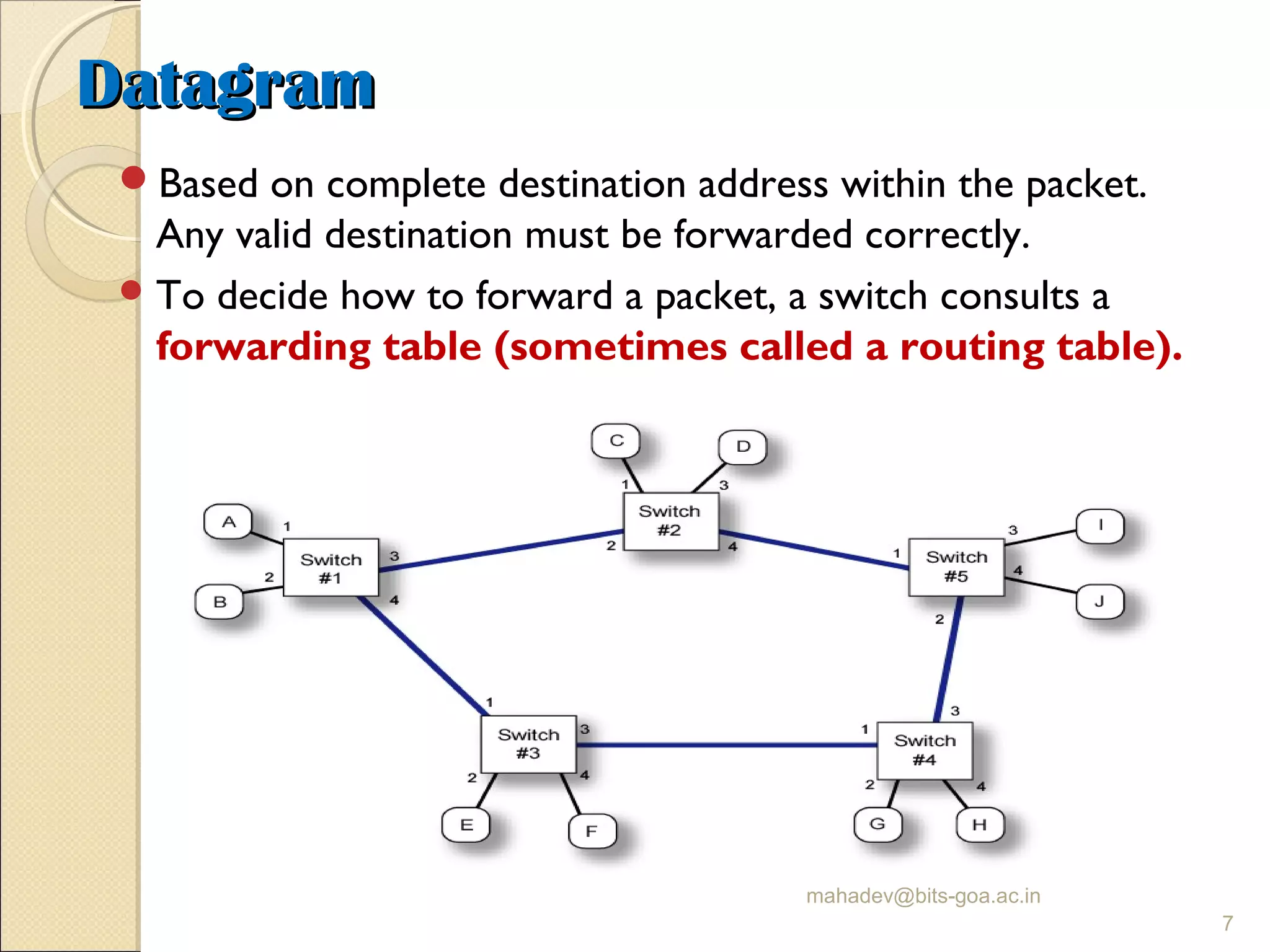
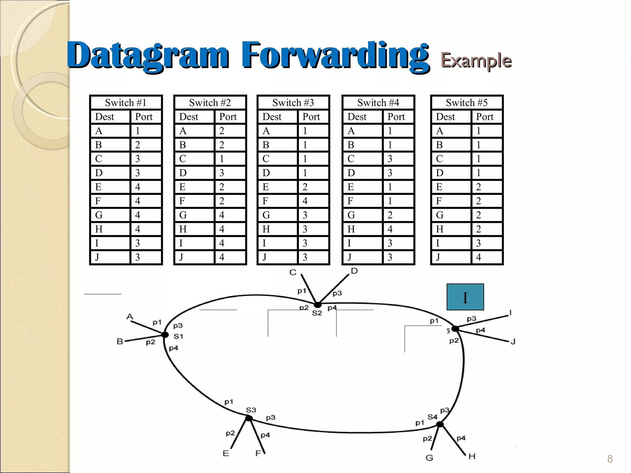
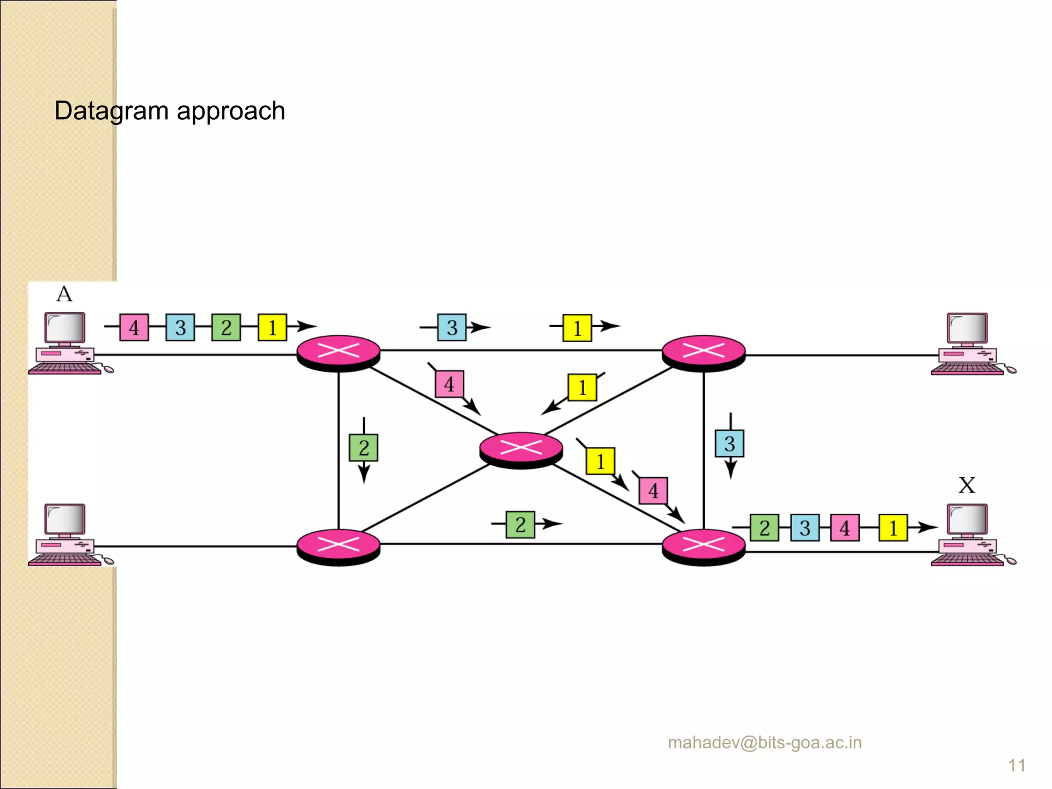
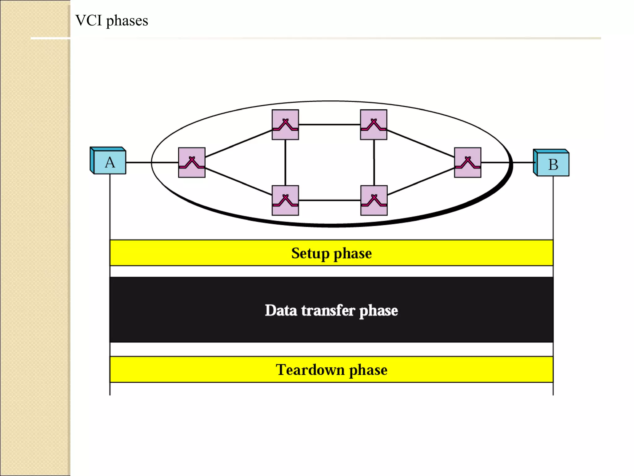
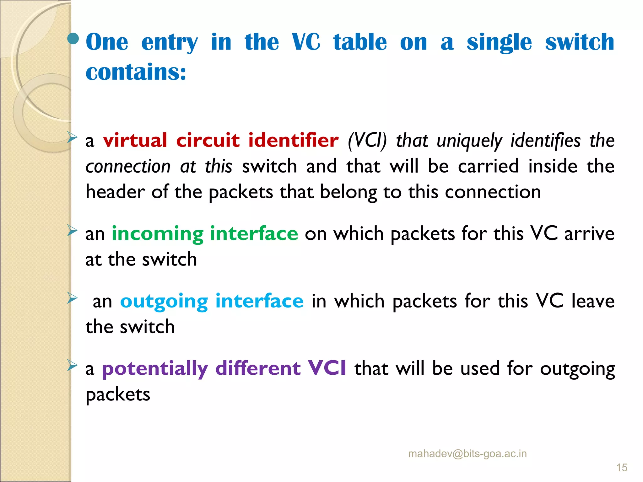
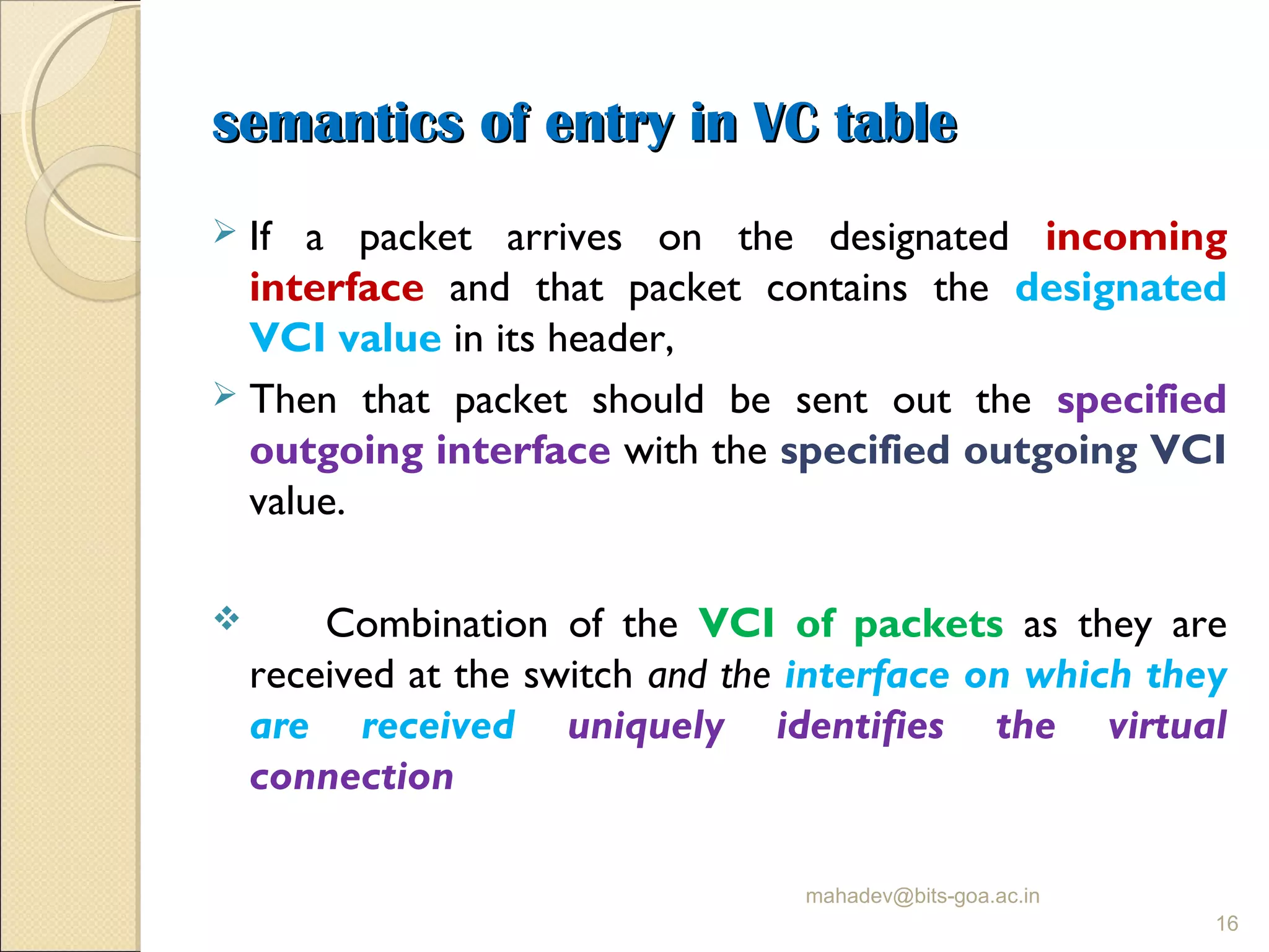
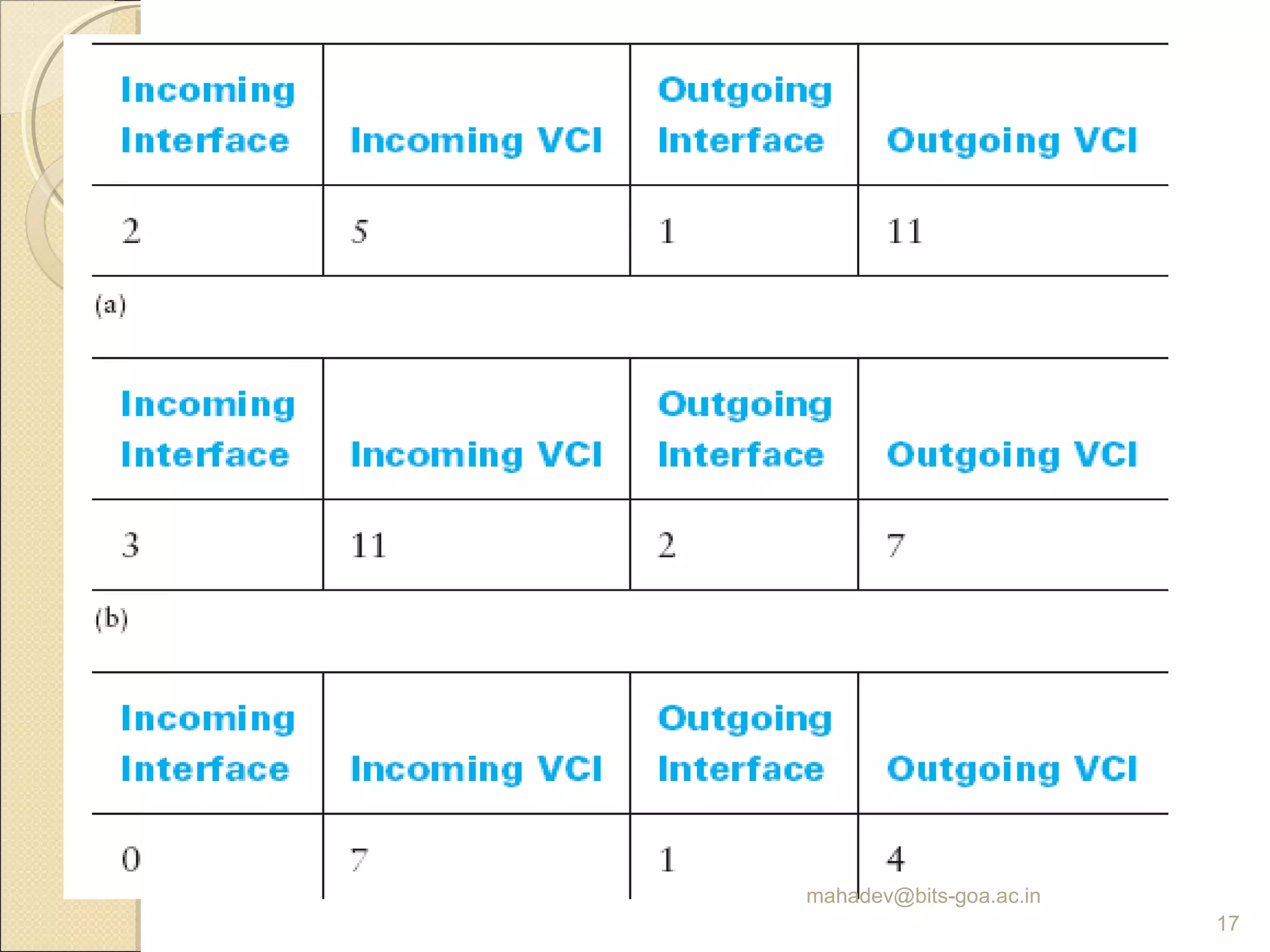
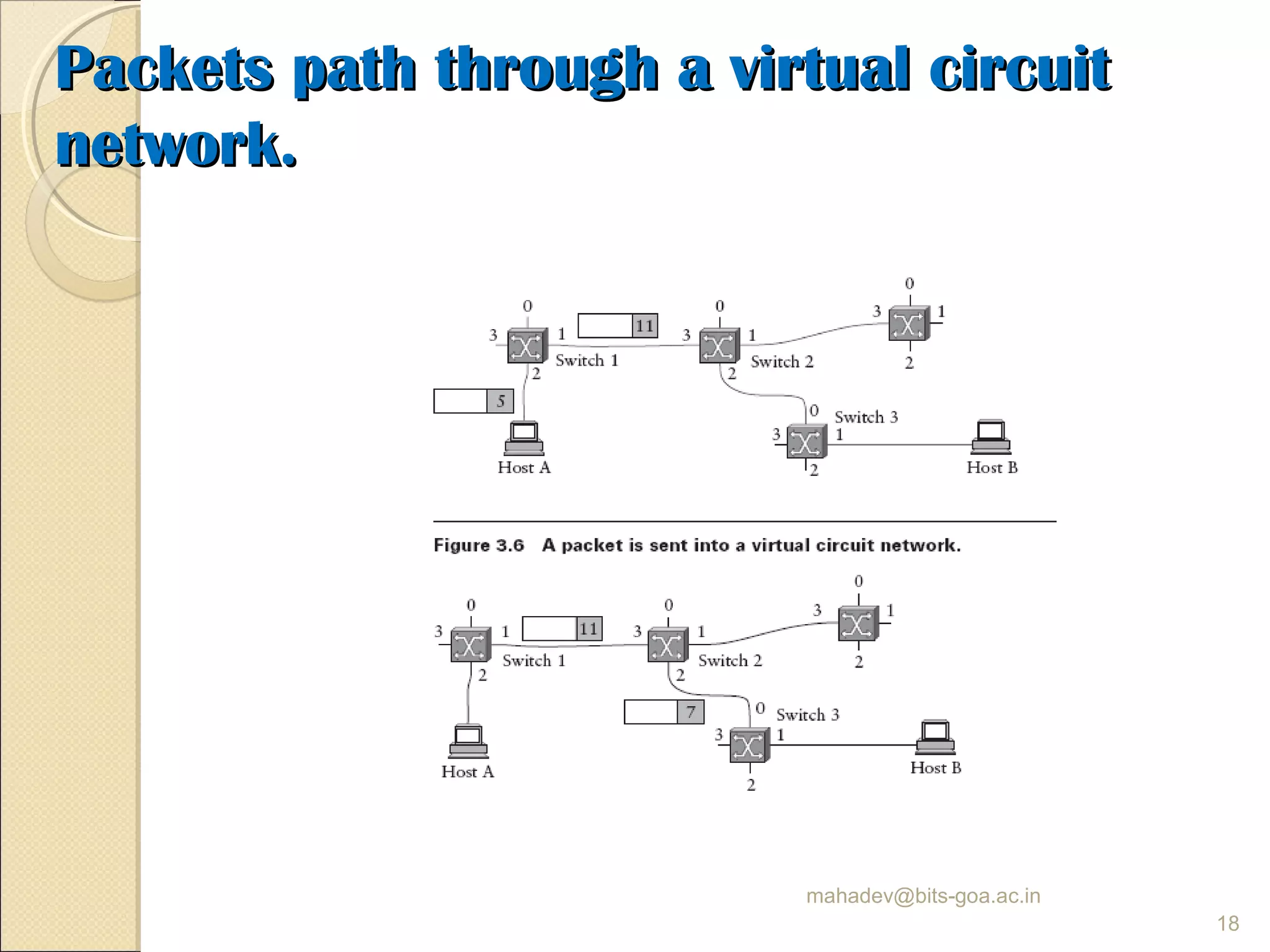
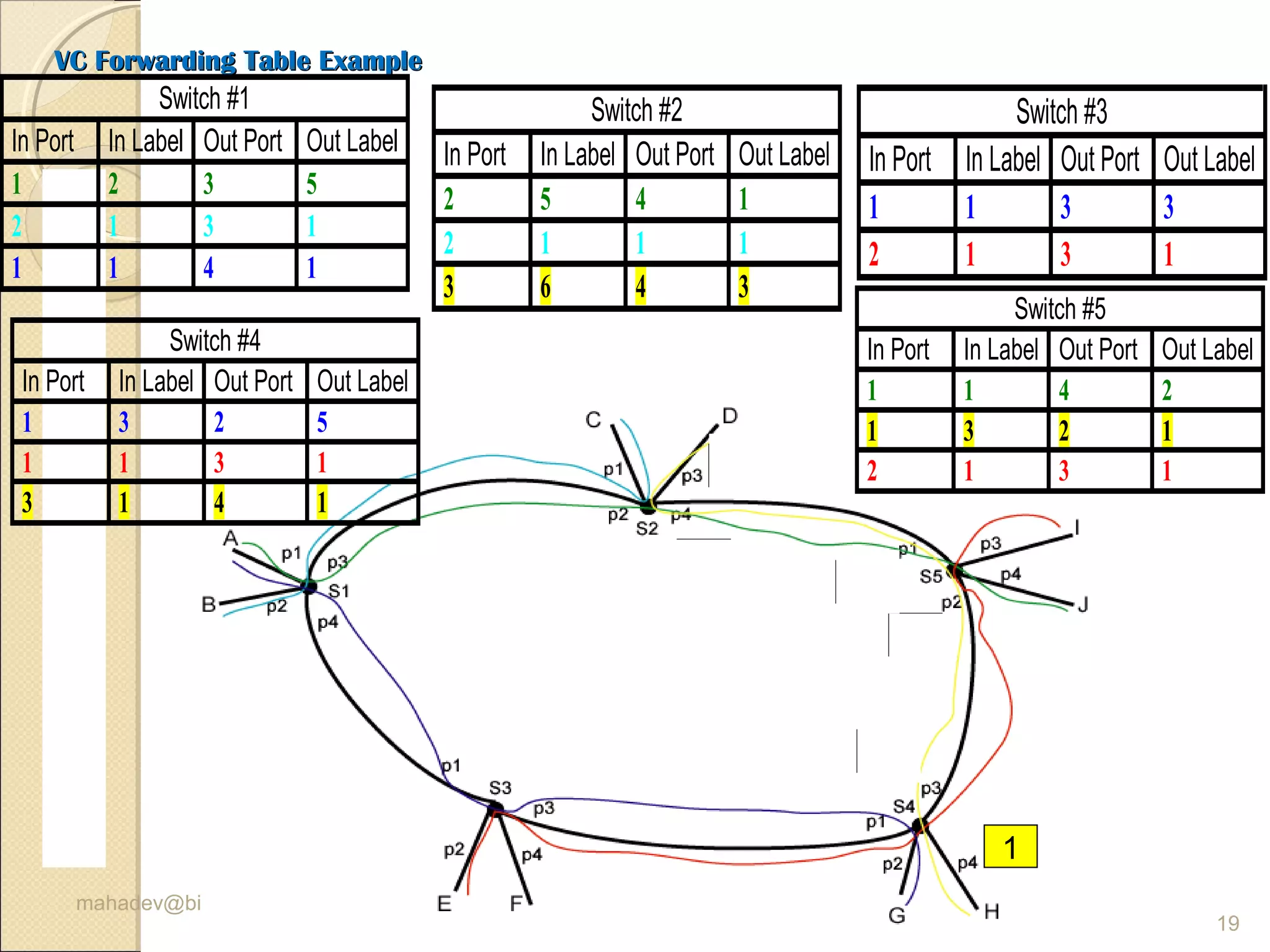
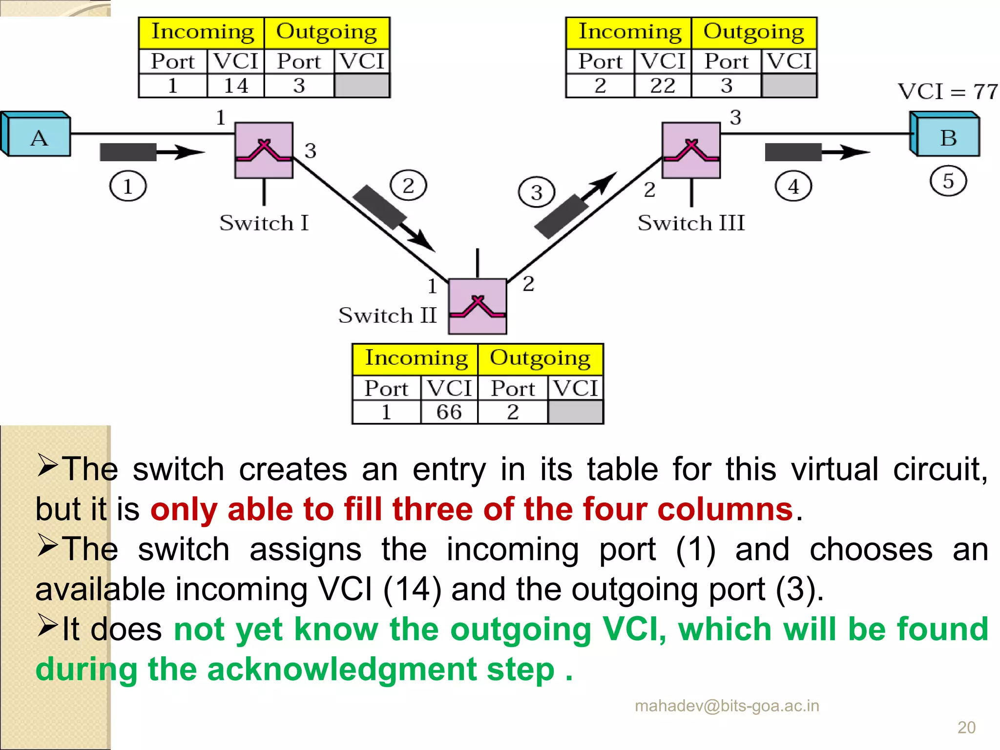
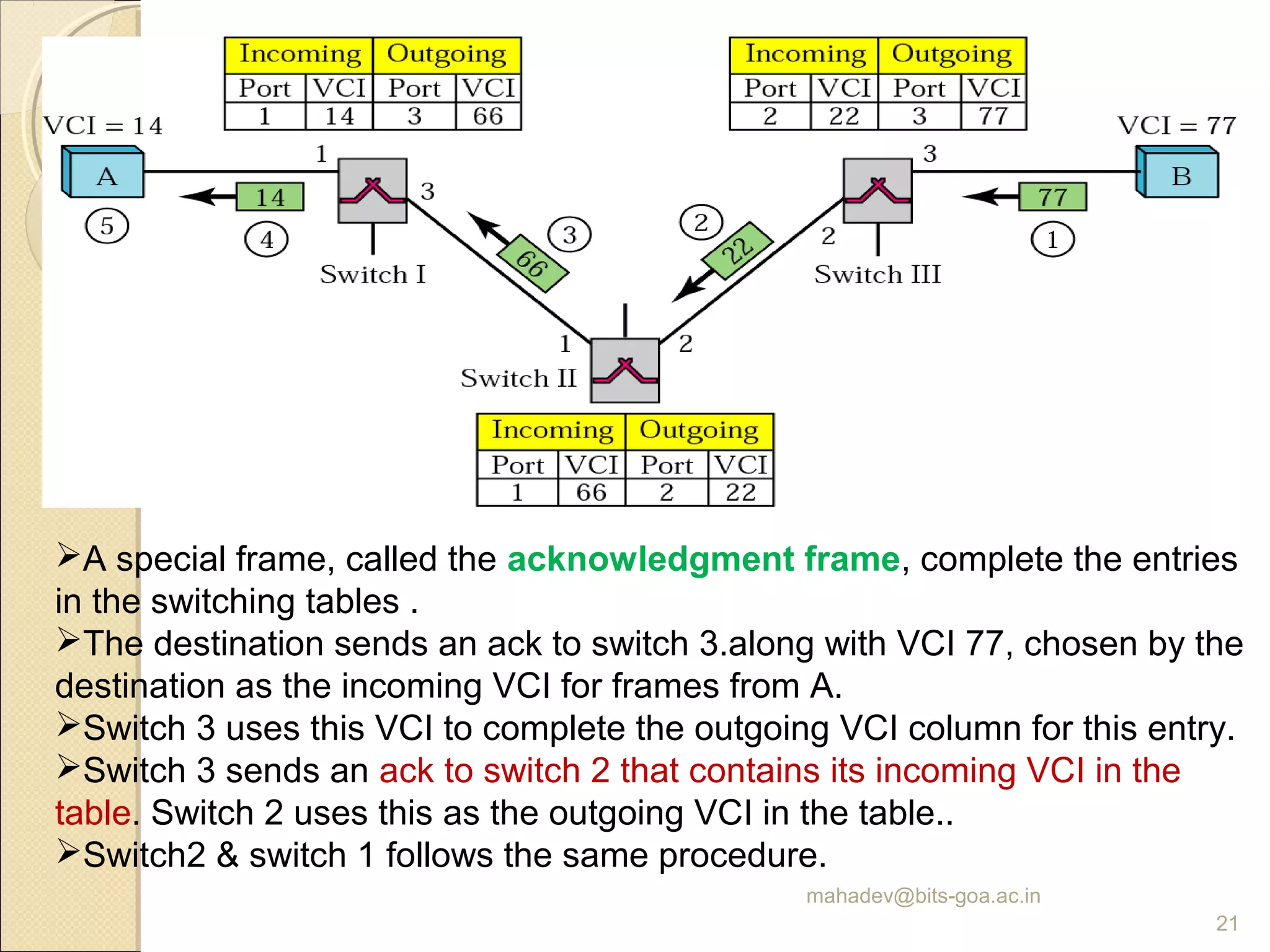
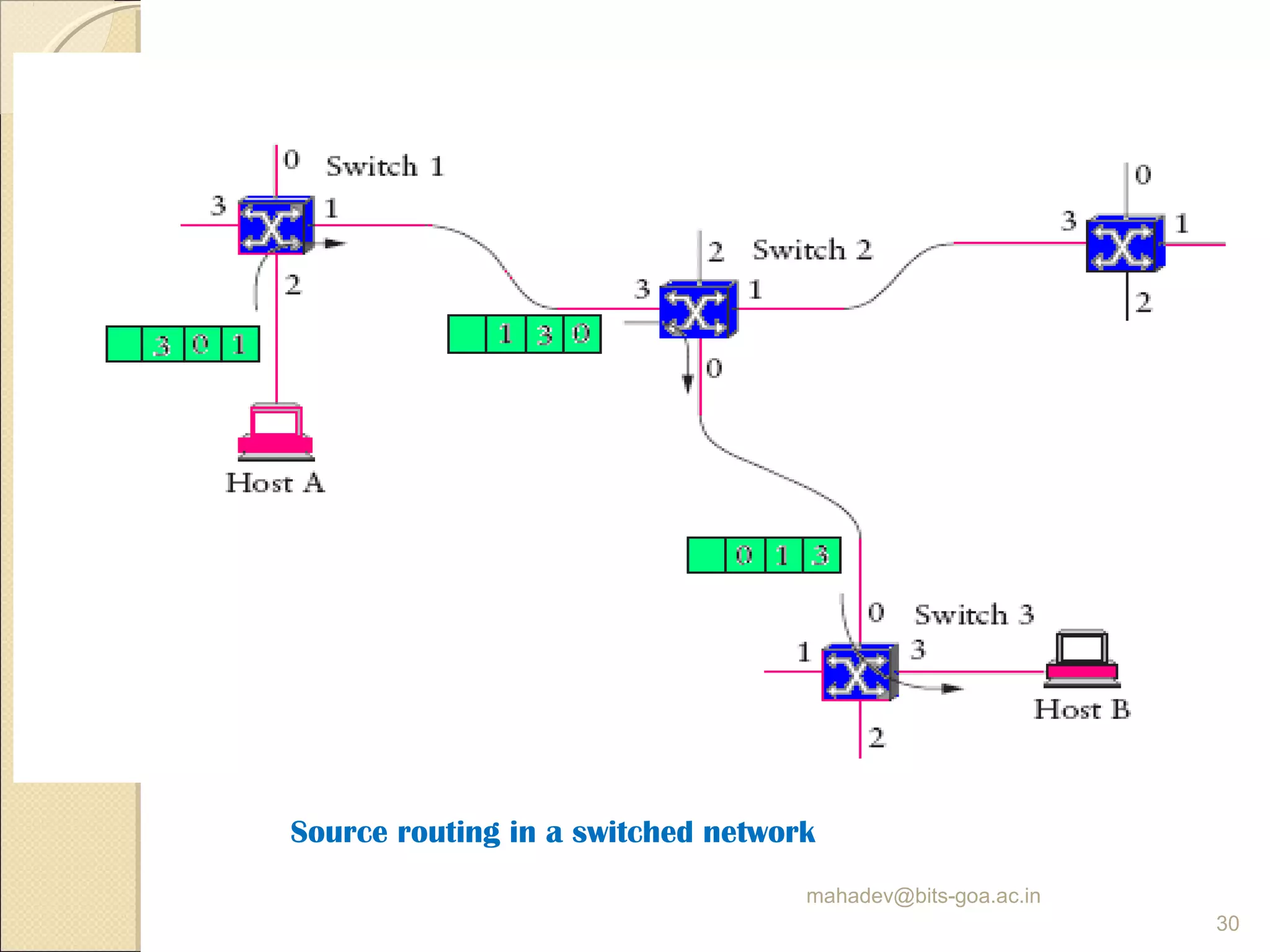

The document discusses packet switching and computer networks. It describes how packet switches enable packets to travel between hosts even without a direct connection by using buffers and queues. It explains the two main approaches to packet switching - connectionless datagram switching which uses destination addresses, and connection-oriented virtual circuit switching which establishes connections using labels. The key aspects of each approach like forwarding tables, signaling process, and connection setup and teardown are outlined.