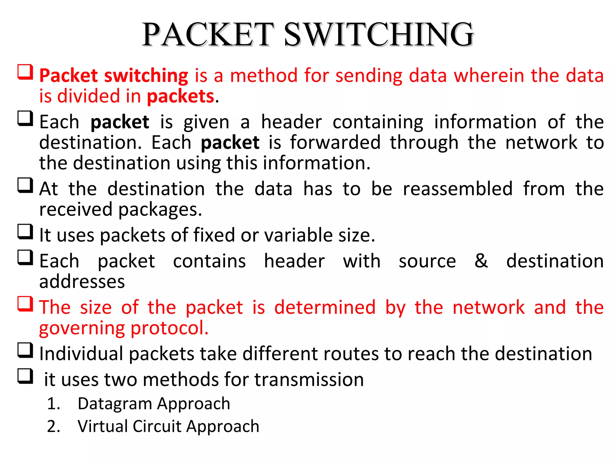
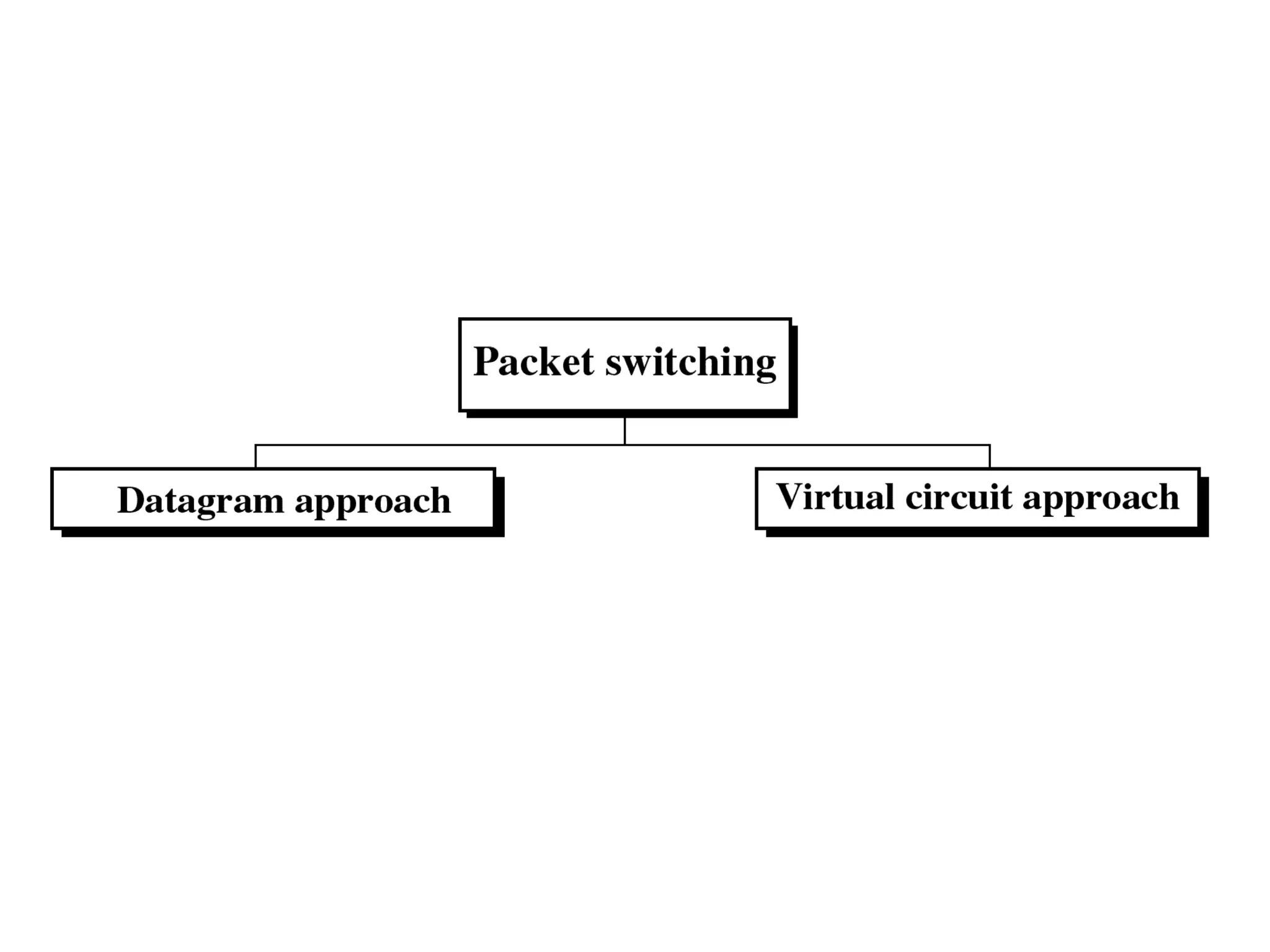
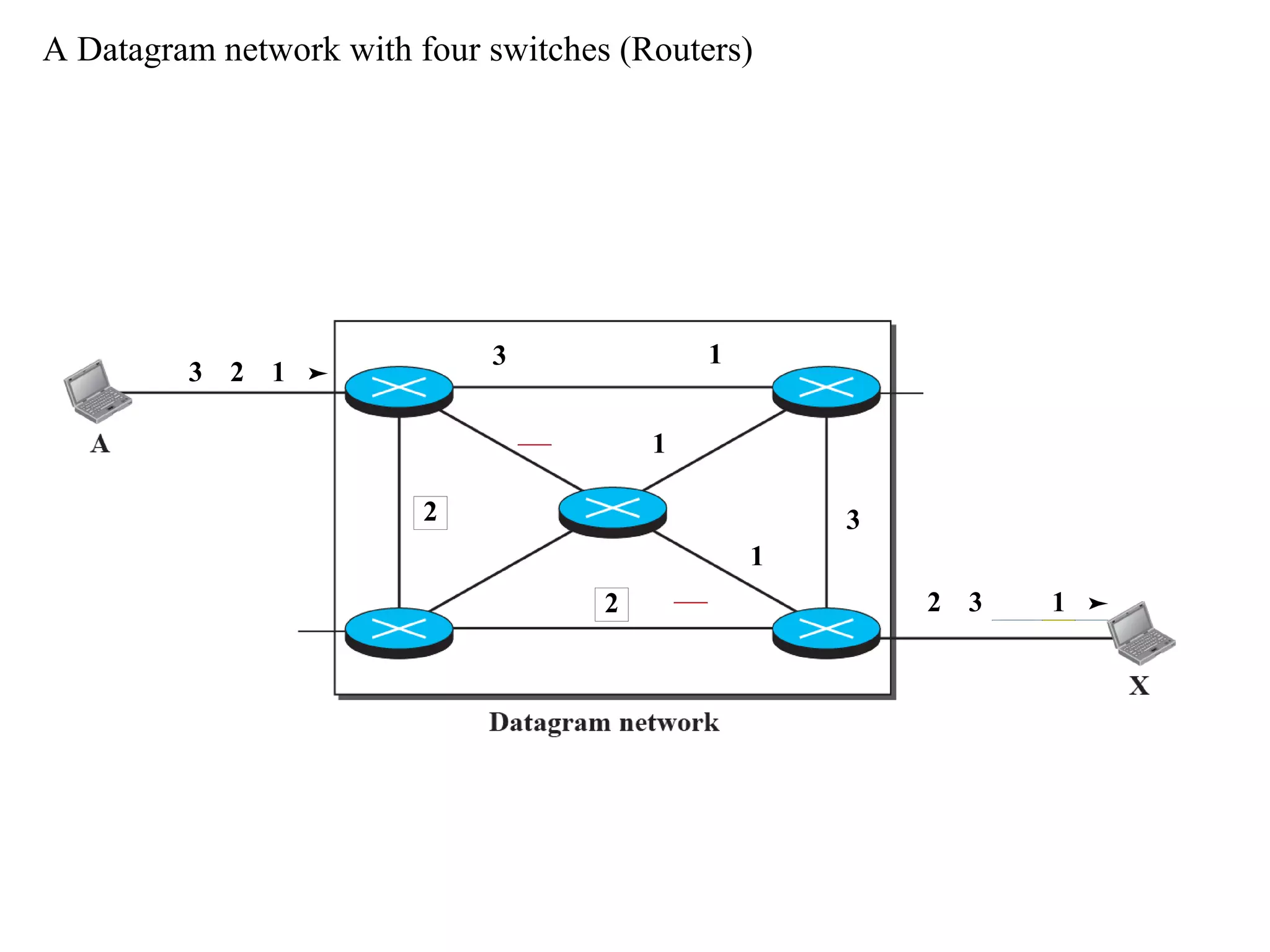
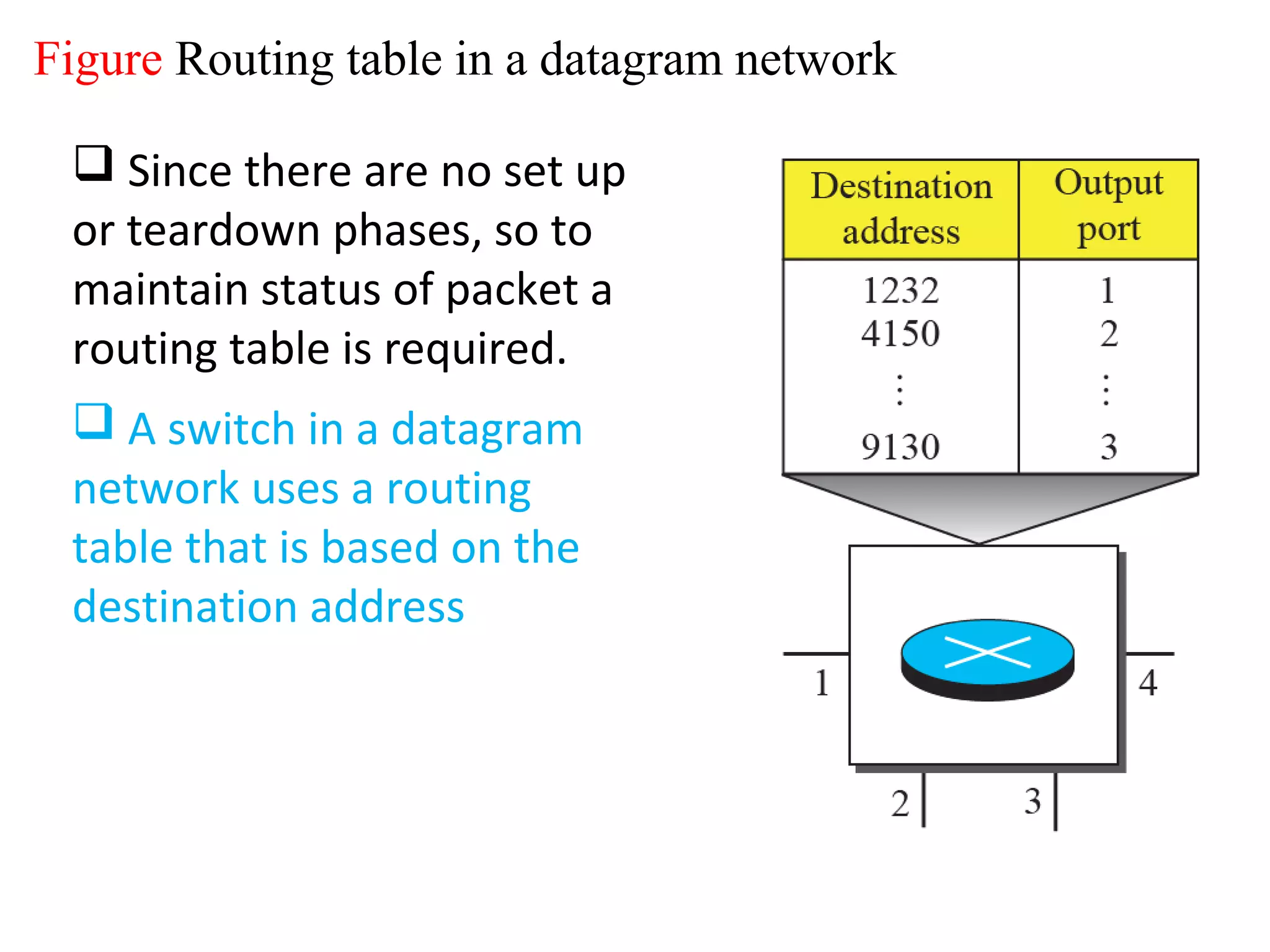
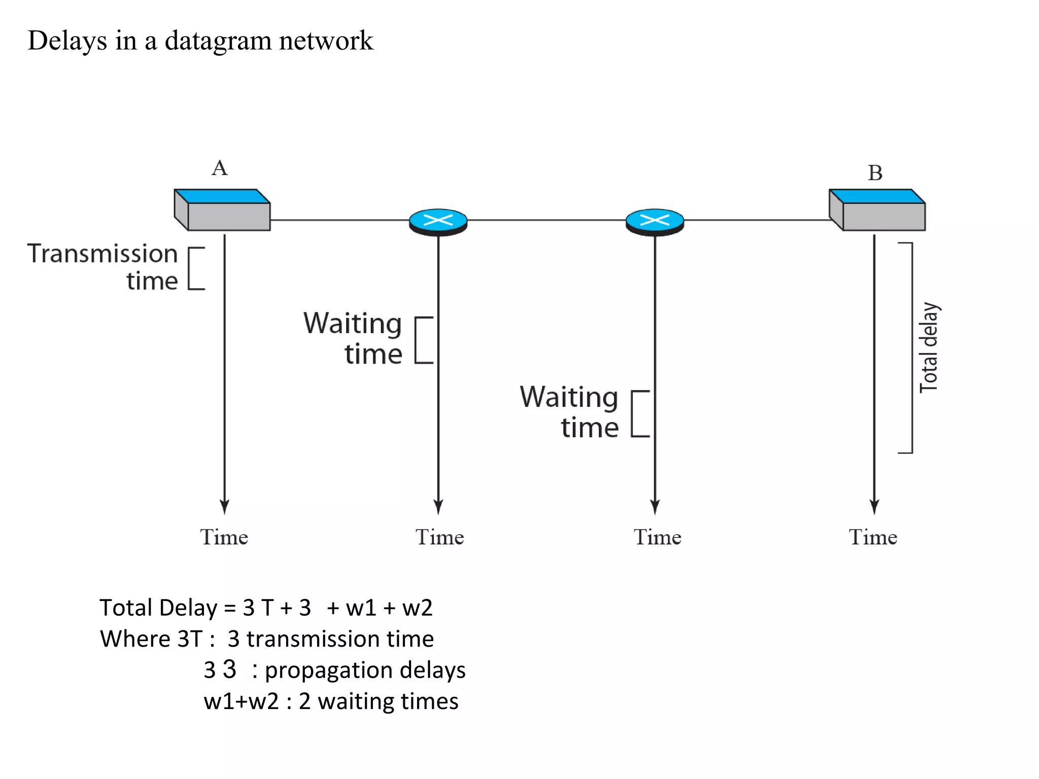
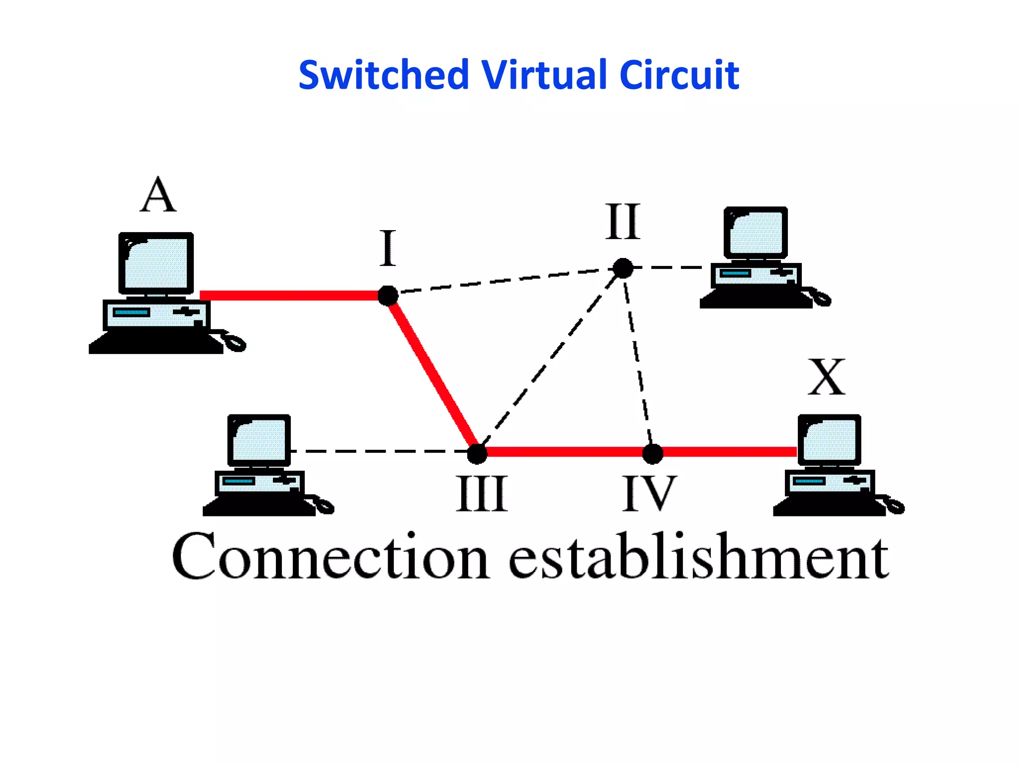
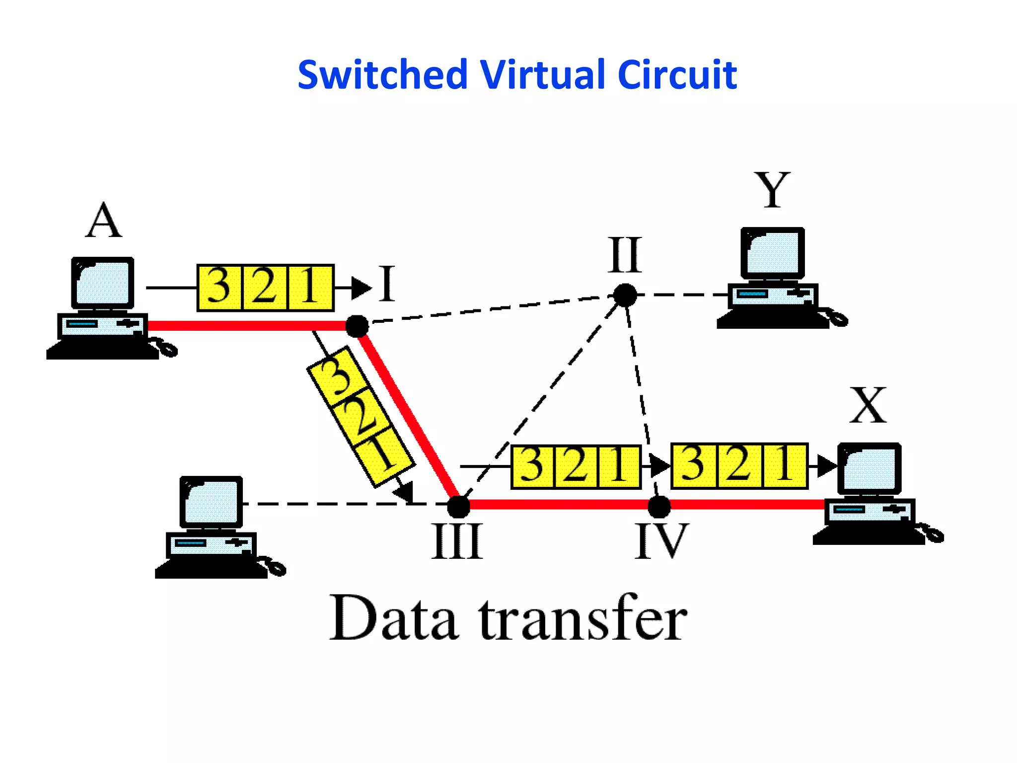
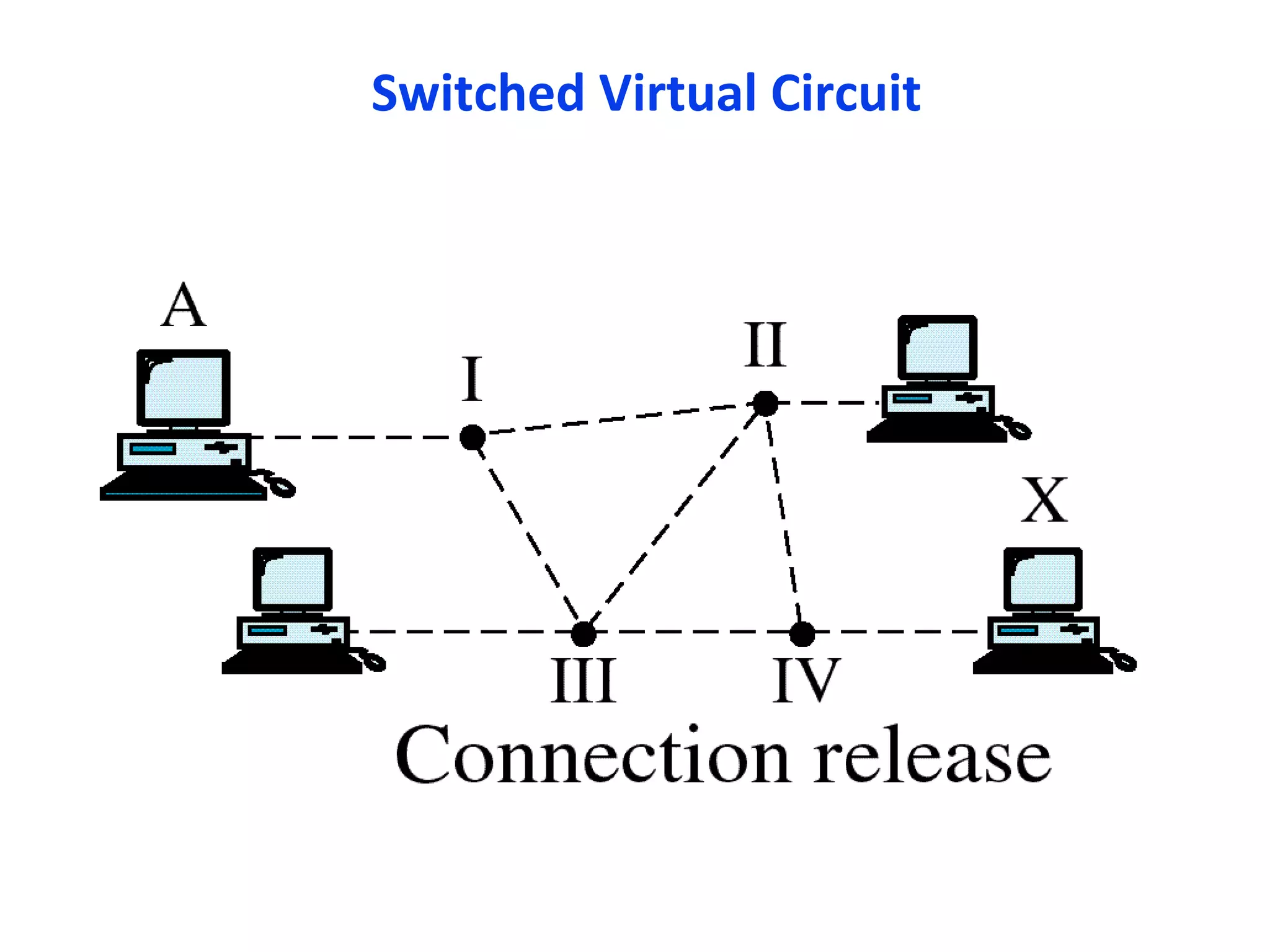
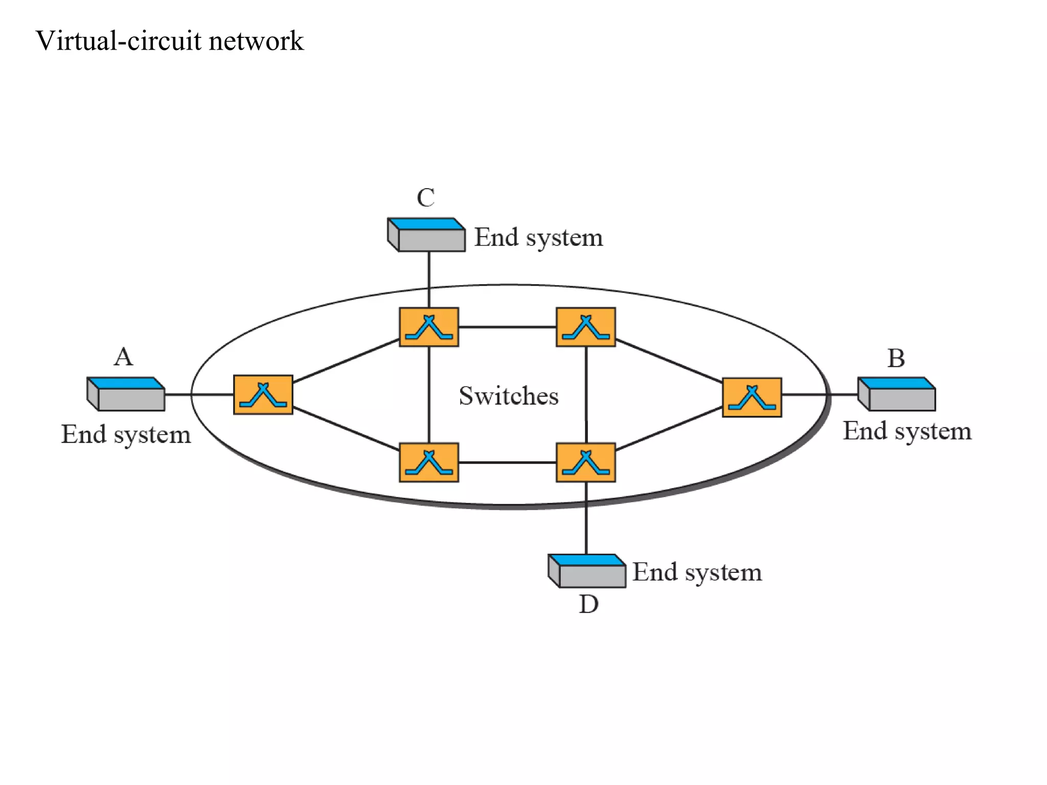
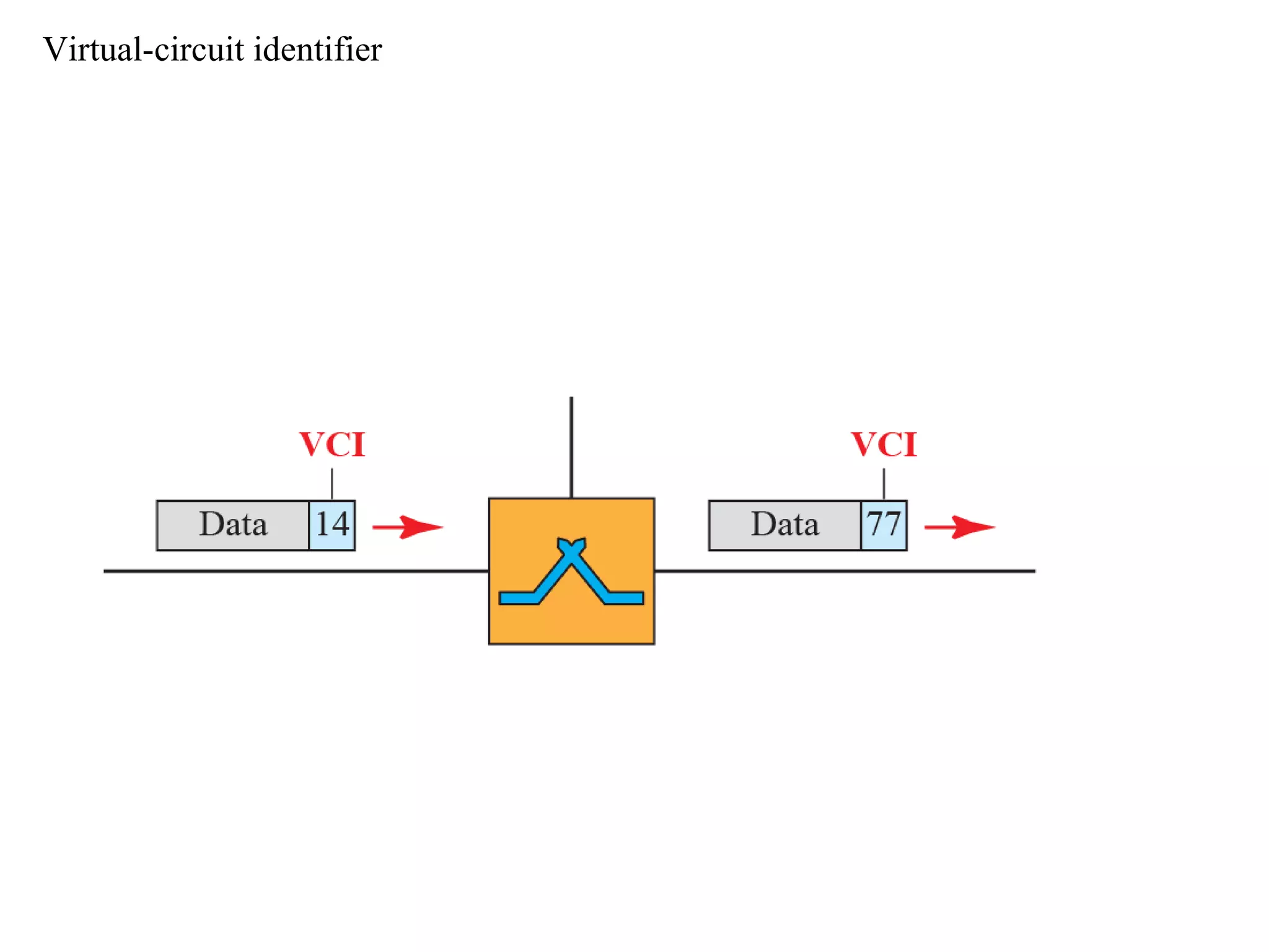
Introduction to Data communication
Topic: Packet Switching
Lecture #7
Dr Rajiv Srivastava
Director
Sagar Institute of Research & Technology (SIRT)
Sagar Group of Institutions, Bhopal
http://www.sirtbhopal.ac.in
Unit 2
Lecture 7
Course Lecture 23
Packet Switching
PACKET SWITCHINGPACKET SWITCHING
 Packet switching is a method for sending data wherein the data
is divided in packets.
 Each packet is given a header containing information of the
destination. Each packet is forwarded through the network to
the destination using this information.
 At the destination the data has to be reassembled from the
received packages.
 It uses packets of fixed or variable size.
 Each packet contains header with source & destination
addresses
 The size of the packet is determined by the network and the
governing protocol.
 Individual packets take different routes to reach the destination
 it uses two methods for transmission
1. Datagram Approach
2. Virtual Circuit Approach
• In a datagram network, each packet is treated independently
of all others.
• Packets in this approach are referred to as datagrams.
• each packet is separately addressed & treated as
independent
• Switches devices route for each packet independently, each
intermediate node defines next route for this packet
• No dedicated connection is established between sender &
receiver
• Resources are not allocated for any packet so there is no
reserved bandwidth or no scheduled processing time for each
packet
DATAGRAM PACKET SWITCHING
• When a switch receives a packet, it has to
wait if there are any other packets being
processed. This increases delay.
• Packet transfer processing takes place at
network layer. These packets are called as
Datagram
• Figure explains the theory of datagram
transmission clearly.
A Datagram network with four switches (Routers)
4 3 2 1
1
4
3
2
1
1
2
3
4
432 1
• The datagram networks are also referred as
connectionless networks, which means it need
to keep track of connections status.
• There are no tear down phases as circuit
switching
• Each packet is treated the same by a switch
regardless of its source or destination.
Figure Routing table in a datagram network
 Since there are no set up
or teardown phases, so to
maintain status of packet a
routing table is required.
 A switch in a datagram
network uses a routing
table that is based on the
destination address
Destination address
• Every packet in the datagram network carries
a header that contains destination address
along with some other information. This
address is used to route the packet to its
destination
• The destination address in the header of the
packet remains unchanged throughout its
journey in the network.
Efficiency
• the efficiency of the datagram network is
better than that of circuit switched network
• Resources are allocated only when the
packets are to be transferred
• If a source sends a packet & there is a delay
of few minutes before another packet can
be sent then the resources can be
reallocated during these minutes for other
packets from other resources.
Delay
• There may be greater delay in datagram
network than virtual circuit network
• There are no setup & tear down phases
• Each packet may experience delay at a switch
before it is forwarded
• Since all packets travel through different
routes/switches so delay is also not identical.
Delays in a datagram network
Total Delay = 3 T + 3 + w1 + w2
Where 3T : 3 transmission time
3 :3 propagation delays
w1+w2 : 2 waiting times
2nd
Approach
Virtual Circuit Network
• Virtual circuit network is implemented at the
data link layer
• a circuit switch network is implemented at
physical layer
• datagram is implemented at network layer.
• A virtual circuit network is a cross between a
circuit switched network & a datagram network.
It has some characteristics of both.
• Similarities with circuit switch:
– Setup & tear down phases
– Resources allocation during setup phase
– All packet follow the same path established during
connection
• Similarities with datagram approach:
– Resources may be allocated on demand
– Data are packetized & each packet carries an
address in the header. However, address in the
header has local jurisdiction, not end to end
jurisdiction
Switched Virtual Circuit
Virtual-circuit network
Addressing in Virtual Circuit Network
• Global Addressing
• Local (virtual Circuit Identifier) VCI
– VCI – it is actual identifier used for data transfer
– It is a small number that has only switch scope
– It is used by frame between two switches
– When a frame arrives at a switch it has different
VCI & when it leaves switch it has another VCI
Virtual-circuit identifier
Thank You
Dr Rajiv Srivastava
Director
Sagar Institute of Research & Technology (SIRT)
Sagar Group of Institutions, Bhopal
http://www.sirtbhopal.ac.in

Topic Packet switching

  • 1.
    Introduction to Datacommunication Topic: Packet Switching Lecture #7 Dr Rajiv Srivastava Director Sagar Institute of Research & Technology (SIRT) Sagar Group of Institutions, Bhopal http://www.sirtbhopal.ac.in
  • 2.
    Unit 2 Lecture 7 CourseLecture 23 Packet Switching
  • 3.
    PACKET SWITCHINGPACKET SWITCHING Packet switching is a method for sending data wherein the data is divided in packets.  Each packet is given a header containing information of the destination. Each packet is forwarded through the network to the destination using this information.  At the destination the data has to be reassembled from the received packages.  It uses packets of fixed or variable size.  Each packet contains header with source & destination addresses  The size of the packet is determined by the network and the governing protocol.  Individual packets take different routes to reach the destination  it uses two methods for transmission 1. Datagram Approach 2. Virtual Circuit Approach
  • 5.
    • In adatagram network, each packet is treated independently of all others. • Packets in this approach are referred to as datagrams. • each packet is separately addressed & treated as independent • Switches devices route for each packet independently, each intermediate node defines next route for this packet • No dedicated connection is established between sender & receiver • Resources are not allocated for any packet so there is no reserved bandwidth or no scheduled processing time for each packet DATAGRAM PACKET SWITCHING
  • 6.
    • When aswitch receives a packet, it has to wait if there are any other packets being processed. This increases delay. • Packet transfer processing takes place at network layer. These packets are called as Datagram • Figure explains the theory of datagram transmission clearly.
  • 7.
    A Datagram networkwith four switches (Routers) 4 3 2 1 1 4 3 2 1 1 2 3 4 432 1
  • 8.
    • The datagramnetworks are also referred as connectionless networks, which means it need to keep track of connections status. • There are no tear down phases as circuit switching • Each packet is treated the same by a switch regardless of its source or destination.
  • 9.
    Figure Routing tablein a datagram network  Since there are no set up or teardown phases, so to maintain status of packet a routing table is required.  A switch in a datagram network uses a routing table that is based on the destination address
  • 10.
    Destination address • Everypacket in the datagram network carries a header that contains destination address along with some other information. This address is used to route the packet to its destination • The destination address in the header of the packet remains unchanged throughout its journey in the network.
  • 11.
    Efficiency • the efficiencyof the datagram network is better than that of circuit switched network • Resources are allocated only when the packets are to be transferred • If a source sends a packet & there is a delay of few minutes before another packet can be sent then the resources can be reallocated during these minutes for other packets from other resources.
  • 12.
    Delay • There maybe greater delay in datagram network than virtual circuit network • There are no setup & tear down phases • Each packet may experience delay at a switch before it is forwarded • Since all packets travel through different routes/switches so delay is also not identical.
  • 13.
    Delays in adatagram network Total Delay = 3 T + 3 + w1 + w2 Where 3T : 3 transmission time 3 :3 propagation delays w1+w2 : 2 waiting times
  • 14.
    2nd Approach Virtual Circuit Network •Virtual circuit network is implemented at the data link layer • a circuit switch network is implemented at physical layer • datagram is implemented at network layer. • A virtual circuit network is a cross between a circuit switched network & a datagram network. It has some characteristics of both.
  • 15.
    • Similarities withcircuit switch: – Setup & tear down phases – Resources allocation during setup phase – All packet follow the same path established during connection • Similarities with datagram approach: – Resources may be allocated on demand – Data are packetized & each packet carries an address in the header. However, address in the header has local jurisdiction, not end to end jurisdiction
  • 16.
  • 17.
  • 18.
  • 19.
  • 20.
    Addressing in VirtualCircuit Network • Global Addressing • Local (virtual Circuit Identifier) VCI – VCI – it is actual identifier used for data transfer – It is a small number that has only switch scope – It is used by frame between two switches – When a frame arrives at a switch it has different VCI & when it leaves switch it has another VCI
  • 21.
  • 22.
    Thank You Dr RajivSrivastava Director Sagar Institute of Research & Technology (SIRT) Sagar Group of Institutions, Bhopal http://www.sirtbhopal.ac.in