1. Fixed Gas Detector
Description
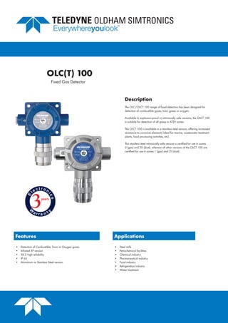
The OLC/OLCT 100 range of fixed detectors has been designed for
detection of combustible gases, toxic gases or oxygen.
Available in explosion-proof or intrinsically safe versions, the OLCT 100
is suitable for detection of all gases in ATEX zones.
The OLCT 100 is available in a stainless steel version, offering increased
resistance to corrosive elements (ideal for marine, wastewater treatment
plants, food processing activities, etc).
This stainless steel intrinsically safe version is certified for use in zones
0 (gas) and 20 (dust), whereas all other versions of the OLCT 100 are
certified for use in zones 1 (gas) and 21 (dust).
Features Applications
• Detection of Combustible, Toxic or Oxygen gases
• Infrared XP version
• SIL 2 high reliability
• IP 66
• Aluminium or Stainless Steel version
• Steel mills
• Petrochemical facilities
• Chemical industry
• Pharmaceutical industry
• Food industry
• Refrigeration industry
• Water treatment
OLC(T) 100
2. OLC(T) 100
Cellule
G
a r a n t i
e
3ans
Se n s or
W
a r r a n t y
3years
2ans
Our products are always application-driven, solution-oriented.
Options include:
• OLCT 100 transmitter with 4-20 mA output
• OLC 100 detector with a Wheatstone bridge output for detection of combustible gases
The infrared sensor provides detection of CO2
and refrigerant gases and is warranty 2 years.
IR Sensor
Fixed Gas Detection
3. OLC(T) 100
OLCT 100 XP
Explosion-proof version is equipped with a catalytic,
electrochemical or semiconductor sensor, for detection of
combustible, toxic gases or oxygen.
OLCT 100 IS
Intrinsically safe version is equipped with an
electrochemical sensor for detection of toxic
gases or oxygen.
OLCT 100 XP IR
Explosion-proof IR version is equipped with an infrared sensor
for detection of CO2
, SF6
and some freons.
OLCT 100 XP HT
High temperature explosion-proof version for
detection of combustible gases up to 200°C.
High temperature cable included: 5, 10, 15
meter lengths.
GAS
HAZARD
Toxic or O2
OLCT 100 XP
OLCT 100 IS
Combustible
OLC 100
OLCT 100 XP HT
OLCT 100 XP
CO2 OLCT 100 XP IR
R134a, R1234yf, R407f OLCT 100 XP IR
SF6
OLCT 100 XP IR
Fixed Gas Detection
4. OLC(T) 100
Fixed Gas Detection
Gas Measure SIL Capability DU
PFDavg
Test Period
Combustibles (a)
Catalytic (C1000) SIL 2 0,189.10-6
8.3 10-4
12 months
O2
(b)(c)
Electrochemical SIL 2 0.74 10-6
1.62 10-3
6 months
CO (b)
Electrochemical SIL 2 1.09 10-6
1.19 10-3
3 months
H2
S (b)
Electrochemical SIL 2 2.98 10-6
3.26 10-3
3 months
NH3
(b)
Electrochemical SIL 2 4.48 10-6
4.91 10-3
3 months
The OLC(T) 100 is SIL 2 certified by INERIS, according to the EN 50402 standard, which corresponds to
IEC/EN 61508 for gas detectors.
(a) complete unit, according to certificate INERIS No. 93664/2012
(b) software and hardware according to certificate INERIS No. 93664/2012, sensors data according to proven in use
(c) O2 sensor with 28 months life expectancy
Reliability
5. OLC(T) 100
Gas
Measuring Range
(ppm)
XP
Version
IS
Version
Temperature Range
(°C)
% RH Accuracy (ppm)
Average Life
Expectancy (month)
Response Time
T50
/T90
(s)
Storage
Condition
Com-
bustible
Gases
Catalytic 0-100% LEL • -40 to +70 0 - 95 +/- 1% LEL (from 0 to 70% LEL) 40 6/15 (CH4
) (b)
Catalytic
High Temperature
0-100% LEL • -20 to +200 0 - 95 +/- 1% LEL (from 0 to 70% LEL) 40 6/15 (CH4
) (b)
AsH3
Arsine 1.00 • -20 to +40 20 - 90 +/- 0.05 18 30/120 (a)
CH2
O Formaldehyde 50.0 • -20 to +50 15 - 90 +/- 1.0 36 50/240 (a)
Cl2
Chlorine 10.0 • -20 to +40 10 - 90 +/- 0.4 24 10/60 (a)
ClO2
Chlorine dioxide 3.00 • -20 to +40 10 - 90 +/- 0.3 24 20/120 (a)
CO Carbon monoxide
100
300
1000
•
•
•
•
•
•
-20 to +50 15 - 90 +/- 3 (range 0-100) 40 15/40 (a)
CO2
Carbon dioxide
0-5000ppm
0-5% vol.
0-10% vol.
0-100% vol.
•
•
•
•
-20 to +40 10 - 90 +/- 3% 48 20/120 (a)
COCl2
Phosgene 1.00 • -20 to +40 15 - 90 +/- 0.05 12 60/180 (c)
ETO Ethylene oxide 30.0 • -20 to +50 15 - 90 +/- 1.0 36 50/240 (a)
H2
Hydrogen 2000 • • -20 to +50 15 - 90 +/- 5% 24 30/50 (a)
H2
S Hydrogen sulfide
30.0
100
1000
•
•
•
•
•
•
-40 to +50 15 - 90 +/- 1.5 (range 0-30) 36 15/30 (a)
HCl Hydrochloric chloride
30.0
100
•
•
-20 to +40 15 - 95 +/- 0.4 (range 0-10) 24 30/150 (a)
HCN Hydrogen cyanide
10.0
30.0
•
•
-40 to +40 15 - 95 +/- 0.3 (range 0-10) 18 30/120 (c)
NH3
Ammonia
1000 • • -40 to +40 15 - 90 +/- 20 24 --
(a)
100
1000
5000
•
•
•
•
•
•
-20 to +40
15 - 90
+/- 5
+/- 20
+/- 150 or 10%
24
25/70
20/60
60/180
NO Nitrogen monoxide
100
300
1000
•
•
•
•
•
•
-20 to +50 15 - 90 +/- 2 (range 0-100) 36 10/30 (a)
NO2
Nitrogen dioxide
10.0
30.0
•
•
-20 to +50 15 - 90 +/- 0.8 24 30/60 (a)
O2
Oxygen
0-30% vol • • -20 to +50 15 - 90
0.4% Vol
(from 15 to 22% O2
)
28 6-15
(a)
0-30% vol • -40 to +50 10 - 90 +/-1,5% 60 15/25
(a)
PH3
Phosphine 1.00 • -20 to +40 20 - 90 +/- 0.05 18 30/120
SiH4
Silane 50.0 • -20 to +40 20 - 95 +/- 1.0 18 25/120 (a)
SO2
Sulphur dioxide
10.0
30.0
100
•
•
•
-20 to +50 15 - 90 +/- 0.7 (range 0-10) 36 15/45 (a)
CH3
Cl Methyl chloride 500 • -20 to +55 20 - 95 +/- 15% (from 20 to 70% FS) 40 25/50 (d)
CH2
Cl2
Methylene chloride 500 • -20 to +55 20 - 95 +/- 15% (from 20 to 70% FS) 40 25/50 (d)
Freon R12 1% vol • -20 to +55 20 - 95 +/- 15% (from 20 to 70% FS) 40 25/50 (d)
Freon R22 2000 • -20 to +55 20 - 95 +/- 15% (from 20 to 70% FS) 40 25/50 (d)
Freon R123 2000 • -20 to +55 20 - 95 +/- 15% (from 20 to 70% FS) 40 25/50 (d)
FX56 2000 • -20 to +55 20 - 95 +/- 15% (from 20 to 70% FS) 40 25/50 (d)
Freon R134 a
2000 • -20 to +55 20 - 95 +/- 15% (from 20 to 70% FS) 40 25/50 (d)
2000ppm • (IR) -20 to +50 0 - 95 +/- 40ppm (from 0 to 50% range) 60 40/170 (e)
Freon R1
1 1% vol • -20 to +55 20 - 95 +/- 15% (from 20 to 70% FS) 40 25/50 (d)
Freon R23 1% vol • -20 to +55 20 - 95 +/- 15% (from 20 to 70% FS) 40 25/50 (d)
Freon R143a 2000 • -20 to +55 20 - 95 +/- 15% (from 20 to 70% FS) 40 25/50 (d)
Freon R404 a 2000 • -20 to +55 20 - 95 +/- 15% (from 20 to 70% FS) 40 25/50 (d)
Freon R507 2000 • -20 to +55 20 - 95 +/- 15% (from 20 to 70% FS) 40 25/50 (d)
Freon R410a 1000 • -20 to +55 20 - 95 +/- 15% (from 20 to 70% FS) 40 25/50 (d)
Freon R32 1000 • -20 to +55 20 - 95 +/- 15% (from 20 to 70% FS) 40 25/50 (d)
Freon R407c 1000 • -20 to +60 20 - 95 +/- 15% (from 20 to 70% FS) 40 25/50 (d)
Freon R407f
1000 • -20 to +55 20 - 95 +/- 15% (from 20 to 70% FS) 40 25/50 (d)
2000 • (IR) -20 to +50 0 - 95 +/- 40ppm (from 0 to 50% range) 60 40/105 (e)
Freon R408a 1000 • -20 to +55 20 - 95 +/- 15% (from 20 to 70% FS) 40 25/50 (d)
Ethanol 500 • -20 to +55 20 - 95 +/- 15% (from 20 to 70% FS) 40 25/50 (d)
Toluene 500 • -20 to +55 20 - 95 +/- 15% (from 20 to 70% FS) 40 25/50 (d)
Isopropanol 500 • -20 to +55 20 - 95 +/- 15% (from 20 to 70% FS) 40 25/50 (d)
2-butanone (MEK) 500 • -20 to +55 20 - 95 +/- 15% (from 20 to 70% FS) 40 25/50 (d)
Xylene 500 • -20 to +55 20 - 95 +/- 15% (from 20 to 70% FS) 40 25/50 (d)
SF6 2000 • (IR) -20 to +50 0 - 95 +/- 40ppm (from 0 to 50% range) 60 25/120 (e)
1000 • -20 to +55 20 - 95 +/- 15% (from 20 to 70% FS) 40 25/50 (d)
R1234yf (HFO) 2000 • (IR) - 20 to +50 0 - 95 +/- 40ppm (from 0 to 50% range) 60 25/120 (e)
0-100% LEL • (IR) - 20 to +50 0 - 95 +/- 2% LEL (from 0 to 50% LEL) 60 30/1
15 (e)
R1234ze 1000 • -20 to +55 20 - 95 +/- 15% (from 20 to 70% FS) 40 25/50 (d)
(a) +4°C to +20°C / 20 % to 60% HR (b) -50°C to +70°C / 20 % to 60 % HR (c) +4°C to +20°C / 20 % to 60 % HR (d) -20°C to +50°C / 20 % to 60 % HR (e) -40°C to +85°C / 0-80% RH
1 bar ± 10 % / 6 month maximum 1 bar ± 10 % / 6 month maximum 1 bar ± 10 % / 3 month maximum 1 bar ± 10 % / 6 month maximum 1 bar ± 10 % / 6 month maximum
Fixed Gas Detection
6. OLC(T) 100
Fixed Gas Detection
Model OLC 100 OLCT 100 XP OLCT 100 XP IR OLCT 100 XP OLCT 100 XP HT OLCT 100 XP OLCT 100 IS
Sensor Catalytic bead Catalytic bead Infrared Electrochemical Catalytic bead Semi-conductor Electrochemical
Material
Epoxy-coated aluminium housing (Inox 316L optional).
316 stainless steel sensors
Dimensions (mm)
(inches)
135 x 133 x 84
5.43 x 5.24 x 3.31"
135 x 133 x 84
5.43 x 5.24 x 3.31"
179 x 138 x 84
7.05 x 5.43 x 3.31"
179 x 138 x 84
7.05 x 5.43 x 3.31"
150 x 138 x 84
5.91 x 5.43 x 3.31"
179 x 138 x 84
7.05 x 5.43 x 3.31"
179 x 138 x 84
7.05 x 5.43 x 3.31"
Weight (kg) 0.95 1 1.1 1.1 1.8 1.1 1.1
Ingress Protection IP66
Cable Entry M20 or ¾ NPT
Supply Voltage
only by OLDHAM
Controller
15.5 to 32 VDC 13.5 to 32 VDC 10 to 32 VDC 15.5 to 32 VDC 15.5 to 32 VDC 15.5 to 32 VDC
Average
Consumption
340 mA 1
10 mA 60 mA 23.5 mA 100 mA 100 mA 23.5 mA
Pressure atmospheric ± 10%
Output signal
Usual source encoded from 0 to 23 mA (not isolated)
- linear 4 to 20 mA output, reserved for measurement
- 0 mA : electronic fault or no power supply
- < 1 mA: fault
- 2 mA: initialization mode
- > 23 mA: out of range
Approvals
Compliant with European directive ATEX 2014/34/EU and with IECEx schedule for explosion-proof detectors.
OLC 100, OLCT 100 XP, OLCT 100 XP IR : ATEX II 2 GD / Ex d IIC T6 Gb / Ex tb IIIC T85°C Db IP66
OLCT 100 XP HT: ATEX II 2 GD / Ex d IIC T6 Gb / Ex tb IIIC T85°C Db IP66 (for the transmitter to be installed in a cold zone)
ATEX II 2 G / Ex d IIC T4..T2 Gb (for the sensor to be installed in the hot zone)
OLCT 100 IS Aluminum : ATEX II 2 GD / Ex ia IIC T4 Gb / Ex ia IIIC T135°C Db IP66
OLCT 100 IS Stainless Steel : ATEX II 1 GD / Ex ia IIC T4 Ga / Ex ia IIIC T135°C Da IP66
SIL 2 according to EN 50402 / EN 61508 for catalytic versions, O2, CO, NH3 and H2S
Metrological performances according to EN/IEC 60079-29-1
Electromagnetic compatibility according to EN 50270
Cable
3 active wires, shielded
cable
3 active wires, shielded
cable
3 active wires, shielded
cable
2 active wires, shielded
cable
3 active wires, shielded
cable
3 active wires, shielded
cable
2 active wires,
shielded cable
7. OLC(T) 100
H
G
J K
I
A
B
C
D E F
A Calibration cup (6331
141)
allows introduction of calibration gas on the sensor
B Bypass adapter (6327910)
allows measurement of samples
C Splash guard system (6329004)
protects the detector from liquid projections
D Remote gas introduction head (632791
1)
allows introduction of gas without opening the detector
E Removable protective filter (6335975)
protects the sensor against projections and dust
F Duct measurement kit (6793322)
allows gas monitoring in a duct
G Mounting bracket (6322420)
allows the mounting of the detector to the ceiling
H Protective cover (6123716)
protects the detector against bad weather conditions or against
direct sun radiations
I Adapter plate (6793718)
allows the replacement of another OLDHAM detector without re-
drilling
J Wall mounted collecting cone (6331
169)
for use with lighter-than-air gases
K Ceiling mount collecting cone (6331
168)
for use with lighter-than-air gases
The reference is broken down as follows:
OLCT 100-XP-001-1
OLCT 100 XP Transmitter, 0-100% LEL CH4
, ATEX, M20 cable entry
Type:
XP
IS
XPIR
Gas:
Codified from 1 to 999,
includes gas and detection
range
Approval and entry of cable range:
1 - ATEX and M20 cable entry - Aluminium
3 - ATEX and 3
/4
NPT cable entry - Aluminium
5 - ATEX and M20 cable entry - Stainless steel
7 - ATEX and 3
/4
NPT cable entry - Stainless steel
Range:
OLC 100
OLCT 100
OLCT 100 HT5*
OLCT 100 HT10*
OLCT 100 HT15*
*Sensor movable up to 5, 10, or 15 meters using a high temperature cable
Accessories
Ordering Information
Fixed Gas Detection