When you finishthis course, you will be able to:
– Identify the various types of shaft seals
– Describe the construction of mechanical seals
– Install shaft packings
– Install seals
– List the pre-seal installation inspection criteria
Course Objectives
4.
Oil Seals
• Oilseals or shaft seals are an integral part
in any rotating and moving part assembly.
• Oil seals find great deal of usage in
gearboxes, hydraulic cylinders, etc.
• The usage of the seals in areas concerned
with motion also earns them a name of
“Dynamic Oil Seals.”
5.
Oil Seals
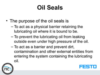
• Thepurpose of the oil seals is
– To act as a physical barrier retaining the
lubricating oil where it is bound to be.
– To prevent the lubricating oil from leaking
outside even under high pressure of the oil.
– To act as a barrier and prevent dirt,
contamination and other external entities from
entering the system containing the lubricating
oil.
6.
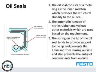
Oil Seals 1.The oil seal consists of a metal
ring as the inner skeleton
which provides the structural
stability to the oil seal.
2. The outer skin is made of
nitrile rubber and various
other materials which are used
based on the requirement.
3. The spring on the lip of the oil
seal tends to provide support
to the lip and prevents the
lubricant from leaking outside
and also prevents the entry of
contaminants from outside.
7.
Oil Seals
• Basedon the application of the oil seal, the outer
skin layer tends to differ.
• Here are some types of the materials used for the
outer skin of the oil seal.
– Nitrile rubber - The commonly used material for oil
seals
– Silicone – Used in specific applications where only light
loads are applied.
– Poly acrylate
– Fluroelastomer also popularly known as Viton. – The
high temperature resistant material used in places
where temperature is more than 120 Degree Celcius.
– PolytetraFluroEthylene (PTFE)
8.
Oil Seals
• Theoils seals require certain prerequisites to be
maintained for their proper working.
• They are as follows:
– The shaft on which the oil seal is to be mounted should be
ground with the surface finish or surface roughness
between 0.2 to 0.8 Microns. It is best for the shaft to be
hardened at least to 40 – 45 HRc in order to prevent
groove formation on the shaft due to the pressure exerted
by the spring.
– The area where the oil seal is seated is to be plunge
ground in order to prevent wear grooves that normally tend
to wear out the lip of the oil seal at a faster rate.
– The lip of the oil seal needs to be lubricated in order to
prevent the direct contact of the oil seal lip to the shaft.
9.
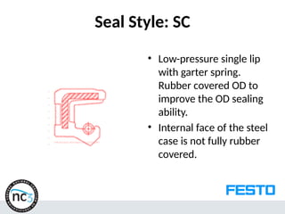
Seal Style: SC
•Low-pressure single lip
with garter spring.
Rubber covered OD to
improve the OD sealing
ability.
• Internal face of the steel
case is not fully rubber
covered.
10.
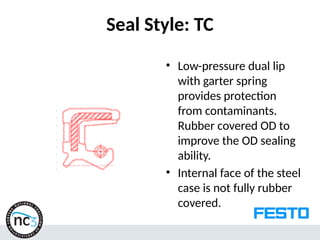
Seal Style: TC
•Low-pressure dual lip
with garter spring
provides protection
from contaminants.
Rubber covered OD to
improve the OD sealing
ability.
• Internal face of the steel
case is not fully rubber
covered.
11.
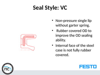
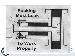
Seal Style: VC
•Non-pressure single lip
without garter spring.
• Rubber covered OD to
improve the OD sealing
ability.
• Internal face of the steel
case is not fully rubber
covered.
12.
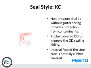
Seal Style: KC
•Non-pressure dual lip
without garter spring
provides protection
from contaminants.
• Rubber covered OD to
improve the OD sealing
ability.
• Internal face of the steel
case is not fully rubber
covered.
13.
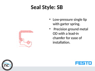
Seal Style: SB
•Low-pressure single lip
with garter spring.
• Precision ground metal
OD with a lead-in
chamfer for ease of
installation.
14.
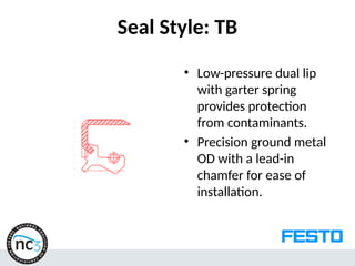
Seal Style: TB
•Low-pressure dual lip
with garter spring
provides protection
from contaminants.
• Precision ground metal
OD with a lead-in
chamfer for ease of
installation.
15.
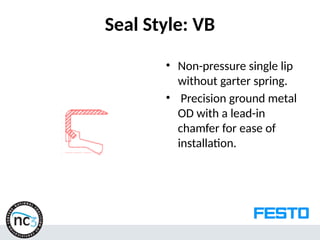
Seal Style: VB
•Non-pressure single lip
without garter spring.
• Precision ground metal
OD with a lead-in
chamfer for ease of
installation.
16.
Seal Style: KB
•Non-pressure dual lip
without garter spring
provides protection
from contaminants.
Precision ground metal
OD with a lead-in
chamfer for ease of
installation.
17.
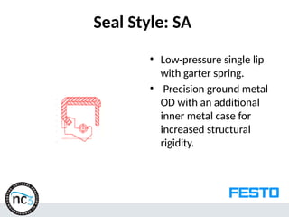
Seal Style: SA
•Low-pressure single lip
with garter spring.
• Precision ground metal
OD with an additional
inner metal case for
increased structural
rigidity.
18.
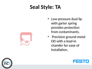
Seal Style: TA
•Low-pressure dual lip
with garter spring
provides protection
from contaminants.
• Precision ground metal
OD with a lead-in
chamfer for ease of
installation.
19.
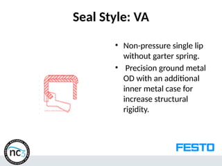
Seal Style: VA
•Non-pressure single lip
without garter spring.
• Precision ground metal
OD with an additional
inner metal case for
increase structural
rigidity.
20.
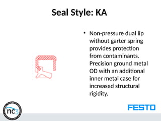
Seal Style: KA
•Non-pressure dual lip
without garter spring
provides protection
from contaminants.
Precision ground metal
OD with an additional
inner metal case for
increased structural
rigidity.
21.
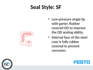
Seal Style: SF
•Low-pressure single lip
with garter. Rubber
covered OD to improve
the OD sealing ability.
• Internal face of the steel
case is fully rubber
covered to prevent
corrosion.
22.
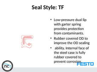
Seal Style: TF
•Low-pressure dual lip
with garter spring
provides protection
from contaminants.
• Rubber covered OD to
improve the OD sealing
• ability. Internal face of
the steel case is fully
rubber covered to
prevent corrosion.
23.
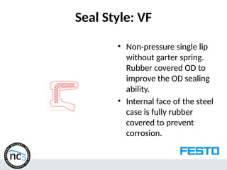
Seal Style: VF
•Non-pressure single lip
without garter spring.
Rubber covered OD to
improve the OD sealing
ability.
• Internal face of the steel
case is fully rubber
covered to prevent
corrosion.
24.
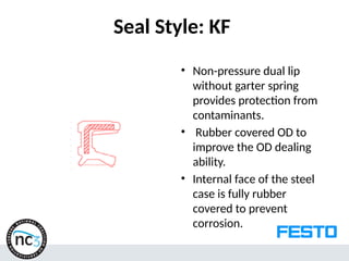
Seal Style: KF
•Non-pressure dual lip
without garter spring
provides protection from
contaminants.
• Rubber covered OD to
improve the OD dealing
ability.
• Internal face of the steel
case is fully rubber
covered to prevent
corrosion.
25.
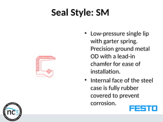
Seal Style: SM
•Low-pressure single lip
with garter spring.
Precision ground metal
OD with a lead-in
chamfer for ease of
installation.
• Internal face of the steel
case is fully rubber
covered to prevent
corrosion.
26.
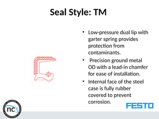
Seal Style: TM
•Low-pressure dual lip with
garter spring provides
protection from
contaminants.
• Precision ground metal
OD with a lead-in chamfer
for ease of installation.
• Internal face of the steel
case is fully rubber
covered to prevent
corrosion.
27.
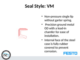
Seal Style: VM
•Non-pressure single lip
without garter spring.
• Precision ground metal
OD with a lead-in
chamfer for ease of
installation.
• Internal face of the steel
case is fully rubber
covered to prevent
corrosion.
28.
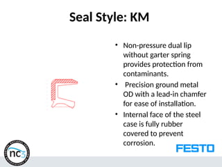
Seal Style: KM
•Non-pressure dual lip
without garter spring
provides protection from
contaminants.
• Precision ground metal
OD with a lead-in chamfer
for ease of installation.
• Internal face of the steel
case is fully rubber
covered to prevent
corrosion.
29.
Review Questions
• Ashaft seal is a barrier designed to retain
lubricants and ________________
Confine pressure, Exclude dirt, Separate fluids
• Selecting the right seal depends on
application parameters, including________?
Shaft speed, Fluid compatibility Operating
pressure
30.
Review Questions
• Typicalradial seal applications include
_________________.Gearboxes, Motors, Pumps
• Simultaneous exclusion and retention is best
performed with _________________ .
a. a combination of two seals back to back
b. single lip design seals
c. a combination of two seals front to back
d. V-Ring seals
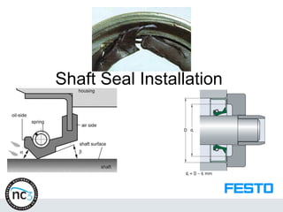
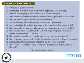
Shaft Seal Installation
•Simple as that may sound, proper seal
installation is not always easy.
• As a matter of fact, it can be quite difficult,
which explains why improper installation is
the number one cause of shaft seal failure!
33.
Pre-Installation
• Because itis the most important part of the
seal, the sealing lip should be closely
inspected to make sure there are no nicks
or tears at any point around its
circumference.
• You should also be certain that the lip is not
turned back.
• Either a torn or turned lip will quickly fail in
service.
34.
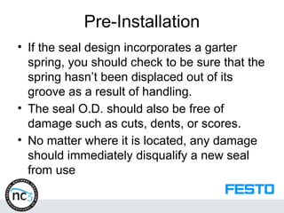
Pre-Installation
• If theseal design incorporates a garter
spring, you should check to be sure that the
spring hasn’t been displaced out of its
groove as a result of handling.
• The seal O.D. should also be free of
damage such as cuts, dents, or scores.
• No matter where it is located, any damage
should immediately disqualify a new seal
from use
35.
Pre-Installation
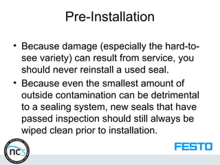
• Because damage(especially the hard-to-
see variety) can result from service, you
should never reinstall a used seal.
• Because even the smallest amount of
outside contamination can be detrimental
to a sealing system, new seals that have
passed inspection should still always be
wiped clean prior to installation.
36.
Pre-Installation
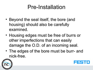
• Beyond theseal itself, the bore (and
housing) should also be carefully
examined.
• Housing edges must be free of burrs or
other imperfections that can easily
damage the O.D. of an incoming seal.
• The edges of the bore must be burr- and
nick-free.
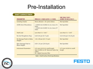
Pre-Installation
• The shaftshould be inspected to ensure
there are no nicks or burrs, and it should
be finished to RMA (Rubber Manufacturing
Association – Publications OS-1 and OS-
1-1) standards as listed in Table 1.
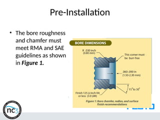
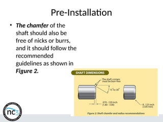
Pre-Installation
• The chamferof the
shaft should also be
free of nicks or burrs,
and it should follow the
recommended
guidelines as shown in
Figure 2.
41.
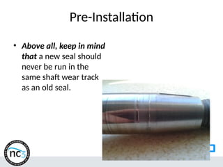
Pre-Installation
• Above all,keep in mind
that a new seal should
never be run in the
same shaft wear track
as an old seal.
42.
Pre-Installation
• If groovingof the shaft surface exists from
previous service, three options are available.
– A spacer can be placed within the bore (behind
the seal) in order to make sure the seal contacts
an un-grooved portion of the shaft.
– A metallic wear sleeve may be fitted over (and, if
need be, adhered to) the damaged shaft to
provide a suitable sealing surface.
• Use of a thin-walled sleeve will normally make it
possible to retrofit a damaged shaft surface without
changing the seal dimensions or design.
– In some cases, it may be necessary to refinish or
replace the shaft.
43.
Installation
• Because ashaft seal should never run
without proper lubrication, both the seal lip
and the shaft should be lubricated (typically
with the same oil or grease being sealed)
prior to installation of the seal.
• In addition to making the installation both
easier and less potentially damaging to the
seal, lubrication also helps protect the
sealing element during the initial break-in
period.
44.
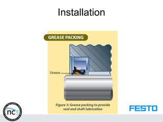
Installation
• Figure 3shows a double lip seal
packed with grease between the primary
and secondary lips.
• When two seals are installed in tandem,
the entire space between the two seals
may be packed with grease.
• In some cases, seal suppliers will pre-lube
seals upon request.
Installation
• As obviousas it may sound, care must be
taken to install the seal in the right direction.
• If replacing a previously used seal, be sure to
note the direction in which the primary lip of the
old seal was facing, then ensure that the
primary lip of the new seal faces the same way.
• Failure to orient the seal properly relative to the
fluid being sealed will result in instantaneous
leakage upon startup.
47.
Installation
• But evenif it’s facing the right direction, the
seal must also be installed at a right angle
(perpendicular) to the centerlines of both the
shaft and the bore.
• Anything less than a right angle means the
seal is angularly misaligned (cocked).
• Installing a standard shaft seal into a
housing can be a problem if there is no
counter-bore to help align and seat the seal.
48.
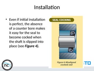
Installation
• Even ifinitial installation
is perfect, the absence
of a counter bore makes
it easy for the seal to
become cocked when
the shaft is slipped into
place (see Figure 4).
49.
Installation
• Seal cockingis most common in blind
designs that prevent the field assembly
team from seeing whether the seal is
properly seated.
50.
Installation
• Seal cockingis problematic for several reasons.
• For example, it can contribute to uneven wearing of the
sealing lip.
• Cocking also increases the chances that any garter spring
might become dislodged from its groove in the lip (known as
spring pop out).
• Damage to the lip itself and/or to the seal O.D. is also more
likely.
• In addition, seal cocking increases the temperature at the
interface between the shaft and the seal lip.
• High temperature hastens hardening and cracking of the
seal.
51.
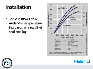
Installation
• Table 2shows how
under-lip temperature
increases as a result of
seal cocking.
52.
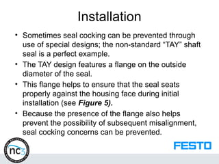
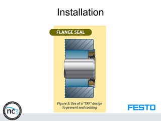
Installation
• Sometimes sealcocking can be prevented through
use of special designs; the non-standard “TAY” shaft
seal is a perfect example.
• The TAY design features a flange on the outside
diameter of the seal.
• This flange helps to ensure that the seal seats
properly against the housing face during initial
installation (see Figure 5).
• Because the presence of the flange also helps
prevent the possibility of subsequent misalignment,
seal cocking concerns can be prevented.
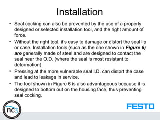
Installation
• Seal cockingcan also be prevented by the use of a properly
designed or selected installation tool, and the right amount of
force.
• Without the right tool, it’s easy to damage or distort the seal lip
or case. Installation tools (such as the one shown in Figure 6)
are generally made of steel and are designed to contact the
seal near the O.D. (where the seal is most resistant to
deformation).
• Pressing at the more vulnerable seal I.D. can distort the case
and lead to leakage in service.
• The tool shown in Figure 6 is also advantageous because it is
designed to bottom out on the housing face, thus preventing
seal cocking.
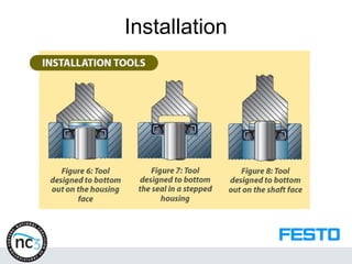
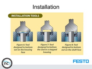
Installation
• Depending onthe specifics of the
application, the tool may also be designed
such that it can keep pressing until the
seal bottoms out (as in a stepped housing,
see Figure 7) or until the tool bottoms
out against the shaft face (see Figure 8).
Installation
• Depending onthe application, the seal may
be installed with the shaft already in place, or
the shaft may be fitted into the assembly after
the seal has been installed into the housing.
• Either way, it is necessary to protect the
sealing lip from splines, keyways, burrs on
the shaft, and improperly finished chamfering
areas.
• Use of a shield and/or lubrication can help.
59.
Installation
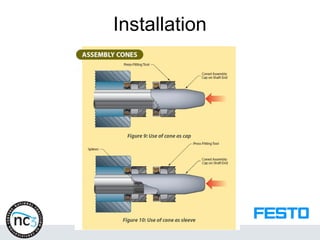
• An assemblycone (acting as either a cap, as in
Figure 9, or a sleeve, as in Figure 10) can be
temporarily fitted onto or over the shaft to
facilitate avoidance of potential hazards.
• If lip inversion (the turning over of the sealing lip
due to friction during installation) is a concern,
the cone can be oiled, or it can be made of a
low-friction material such as PTFE.
• Assembly cones must be routinely inspected to
make sure they have no burrs or scratches.
Installation
• But evenproper tools are no guarantee of good installation.
• Without the right amount of force, the seal will still not be
installed properly.
• If installation is taking place in a factory, this force is often
supplied by a hydraulic or pneumatic press.
• Use of such automated presses can eliminate guesswork by
providing a constant force with which to push the seal into its
housing.
• Because this force is closely controlled, the chances of
inadvertently damaging the seal are greatly reduced.
• Factory installations also tend to be cleaner due to the ability
to more closely control the work environment.
62.
Installation
• In contrast,installations done in the field tend to be both dirtier
(due to reduced environmental control) and less precise (due
to forced reliance on less reliable installation aids).
• Tools such as those used in factories aren’t as common in the
field.
• Installation force is often provided solely by hand-operated
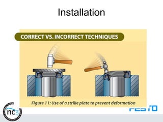
• arbor presses or soft-faced mallets (used in conjunction
• with strike plates, see Figure 11).
• The results are almost always less consistent than with
automated equipment.
• Because of these inconsistencies, the chances of
inadvertently damaging the seal are greater.
Installation
• In somecases, it may be helpful to apply a thin coat
of bore sealant to the O.D. of the seal.
• This adhesive coating can help the seal stay in place
(and form a more leak-proof seal) once it’s installed in
the housing.
• Be careful, however, that any sealant you may use
does not contaminate other parts of the seal,
particularly the lip, or the surface of the shaft.
• Such contamination can impair or inhibit the
functioning of the seal by blocking the proper
development of the lip-shaft interface.
65.
Post Installation
• Youshould also be cognizant of any treatments (such
as painting or cleaning) to which the assembly in
general (and the seal in particular) may be subjected.
• Unless proper precautions are taken to shield the
seal, post installation treatments can impair the seal’s
functionality and thus hasten its failure.
• For example, you should be careful to ensure that a
painted assembly does not remain in the bake oven
any longer than necessary to cure the paint;
prolonged heat exposure can be very detrimental to
the seal lip material.
66.
Post Installation
• Finally,the overall design of the assembly can hold
hidden dangers that, if not addressed, can doom any
shaft seal.
• For example, the assembly must provide adequate
ventilation for the internal pressure within the seal area.
• Without proper ventilation, pressure can build to
dangerous levels, even to the point of blowing the seal
out of its housing.
• If a vent exists, make sure it is not clogged during
painting.
• Clogged vents can cause excessive pressure to build
up that could blow out the seal.
68.
Review Questions
• True/FalseWhen the seal’s basic function is to
retain, the lip of the seal should face away from
the lubricant or pressure being retained. False
• _________________ is the most popular
material for the majority of sealing applications
today.
a. Leather
b. Felt
c. Nitrile
d. Silicone
69.
Review Questions
• _________________refers to the outside
diameter of the shaft at the location where
• the seal is mounted.
a. Size bore
b. Seal I.D.
c. Seal width
d. Shaft diameter
70.
Review Questions
The sealis ready to be installed in the bore
when _________________ .
a. the shaft and bore have been checked
and cleaned
b. the seal has been pre-lubricated
c. both of the above
d. none of the above
71.
Review Questions
For bestseal performance, use a(n)
_________________ or soft-face hammer
for seal installation.
a. screwdriver
b. arbor press
c. chisel
d. steel hammer
72.
Review Questions
• True/False. A direct blow on one side of the seal
distorts the shell and can cause the lip to be
pressed against the shaft. True
The wrong installation tool can _________ .
a. cut the seal lip
b. damage the seal case
c. distort the seal
d. all of the above
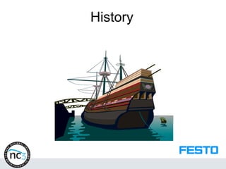
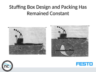
History
• Primitive manbuilt boats for fishing and to
explore his world
• The rudder appeared in some of the
original boat designs
• Sailors could steer or navigate their boats
by rotating the rudder shaft
75.
History
• The holein the bottom of the boat where
the rudder shaft passed through was a
point of leakage where water entered
• Early ship builders designed a housing
around the rudder shaft hole with a type of
gland press. The sailors stuffed their old
clothes, hair, rotten ropes, sails, leather
scraps and grease into the housing and
tightened the press
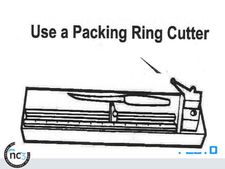
Reciprocating Action
• In1712 the reciprocating steam engine became
a reality. Inside the engine a load of steam was
discharged against a piston and reciprocating
shaft
• Through a crankshaft mechanism the
reciprocating shaft made propulsion
paddlewheels rotate
• In order to contain the steam inside the cylinders
with the reciprocating rods and pistons the
stuffing box design was incorporated, with its
box housing, gland, and stopa material
78.
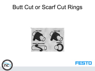
Stopa Becomes Packing
•The old rudder shaft of the ancient boat
only moved sufficiently to change the
direction of the boat
• The reciprocating shaft of the steam
engine is in constant movement with more
velocity and friction
• Compare the temperature and pressure of
seawater against the rudder packing with
steam against the constantly moving shaft
79.
Stopa Becomes Packing
•With refinements and improvements in
steam engines the pressure rapidly
climbed
• The industry stopped using the word
“stopa” and adopted the term packing
• The new packing on reciprocating steam
rods could withstand the temperatures,
abrasion and pressures generated by
steam
80.
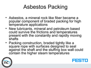
Asbestos Packing
• Asbestos,a mineral rock like fiber became a
popular component of braded packing for high
temperature applications
• New lubricants, mineral and petroleum based
could survive the frictions and temperatures
present with the constantly and rapidly moving
shafts
• Packing construction, braded tightly like a
square rope with surfaces designed to seal
against the shaft and the stuffing box wall could
contain the higher steam temperatures
81.
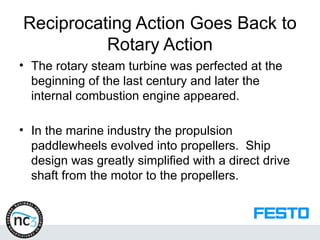
Reciprocating Action GoesBack to
Rotary Action
• The rotary steam turbine was perfected at the
beginning of the last century and later the
internal combustion engine appeared.
• In the marine industry the propulsion
paddlewheels evolved into propellers. Ship
design was greatly simplified with a direct drive
shaft from the motor to the propellers.
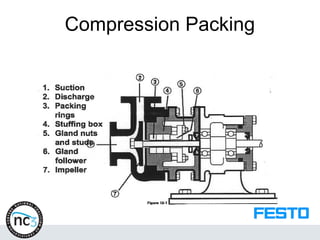
Compression Packing
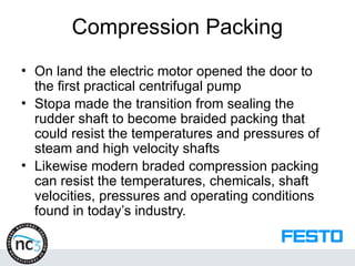
• Onland the electric motor opened the door to
the first practical centrifugal pump
• Stopa made the transition from sealing the
rudder shaft to become braided packing that
could resist the temperatures and pressures of
steam and high velocity shafts
• Likewise modern braded compression packing
can resist the temperatures, chemicals, shaft
velocities, pressures and operating conditions
found in today’s industry.
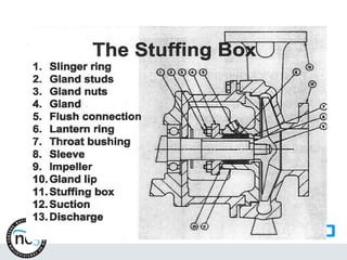
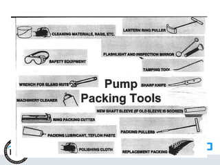
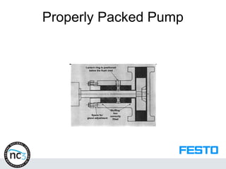
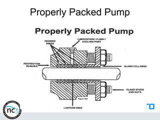
The Lantern Ringand Flush
• Supplies additional lubricant to the packing rings
• Supplies “back pressure” tot eh pumped fluid to
prevent the entrance of abrasive and corrosive
material into the stuffing box
• Cools and cleans the packing shaft
96.
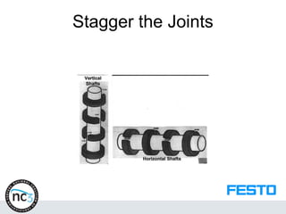
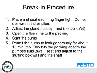
Break-in Procedure
1. Placeand seat each ring finger tight. Do not
use wrenched or pliers
2. Adjust the gland nuts by hand (no tools Yet)
3. Open the flush line to the packing
4. Start the pump
5. Permit the pump to leak generously for about
15 minutes. This lets the packing absorb the
pumped fluid ,swell, seat and adjust to the
stuffing box wall and the shaft
97.
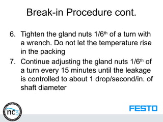
Break-in Procedure cont.
6.Tighten the gland nuts 1/6th
of a turn with
a wrench. Do not let the temperature rise
in the packing
7. Continue adjusting the gland nuts 1/6th
of
a turn every 15 minutes until the leakage
is controlled to about 1 drop/second/in. of
shaft diameter
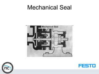
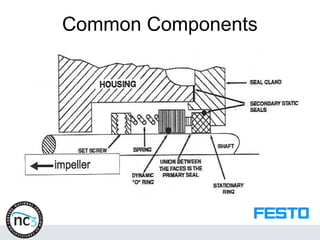
Why Use MechanicalSeals?
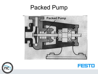
Pump Shaft Packing
• Requires maintenance
• Leaks
• Consumes high energy
• Reduces efficiency
• Corrodes
• Stresses bearings
• Contaminated the lube
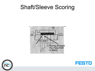
• Destroys the shaft/sleeve
• Contaminates the environment
103.
Are Mechanical SealsReliable?
• The family car has about 6 pumps with
seals:
– The radiator water pump
– The fuel pump
– The oil pump
– The power steering pump
– The windshield washer fluid pump
– The air conditioning compressor
104.
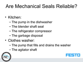
Are Mechanical SealsReliable?
• Kitchen:
– The pump in the dishwasher
– The blender shaft seal
– The refrigerator compressor
– The garbage disposal
• Clothes washer:
– The pump that fills and drains the washer
– The agitator shaft
105.
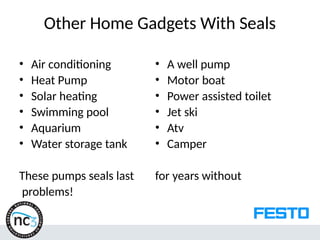
Other Home GadgetsWith Seals
• Air conditioning
• Heat Pump
• Solar heating
• Swimming pool
• Aquarium
• Water storage tank
These pumps seals last
problems!
• A well pump
• Motor boat
• Power assisted toilet
• Jet ski
• Atv
• Camper
for years without
106.
Industrial Pump Seals
•Environmental laws favor mechanical
seals
• The need to conserve energy favors
mechanical seals
• The need to reduce labor costs and
consumption of natural resources favor the
mechanical seal over packing.
107.
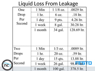
Liquid Loss FromLeakage
One
Drop
Per
Second
1 Min 1 1/8 oz. .0029 ltr.
1 hr. 6 oz. .18 ltr.
1 day 9 pts. 4.26 ltr.
1 week 8 gal. 30.28 ltr.
1 month 34 gal. 128.69 ltr.
Two
Drops
Per
Second
1 Min 1/3 oz. .0089 ltr.
1 hr. 20 oz. .59 ltr.
1 day 15 qts. 13.88 ltr.
1 week 26 gal. 98.41 ltr.
1 month 100 gal. 378.5 ltr.
108.
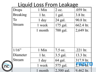
Liquid Loss FromLeakage
Drops
Breaking
To
Stream
1 Min 2 oz. .059 ltr.
1 hr. 1 gal. 3.8 ltr.
1 day 24 gal. 90.8 ltr.
1 week 175 gal. 662.4 ltr.
1 month 700 gal. 2,649 ltr.
1/16”
Diameter
Stream
1 Min 7.5 oz. .221 ltr.
1 hr. 3.5 gal. 13.3 ltr.
1 day 64 gal. 317.9 ltr.
1 week 575 gal. 2,176 ltr.
1 month 2,500 gal. 9,462 ltr.
109.
Industrial Pump Seals
•Most pump manufacturers offer their products
with standard or optional mechanical seals
• Most seal manufacturers make seal models
designed to directly substitute packing
• The majority of pumps can be converted to
mechanical seals without machining or design
change
• Other pumps can be converted with a slight
design adjustment that will not alter the flow or
head
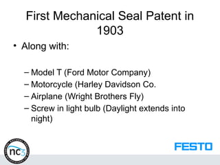
First Mechanical SealPatent in
1903
• Along with:
– Model T (Ford Motor Company)
– Motorcycle (Harley Davidson Co.
– Airplane (Wright Brothers Fly)
– Screw in light bulb (Daylight extends into
night)
113.
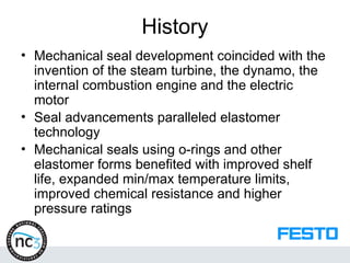
History
• Mechanical sealdevelopment coincided with the
invention of the steam turbine, the dynamo, the
internal combustion engine and the electric
motor
• Seal advancements paralleled elastomer
technology
• Mechanical seals using o-rings and other
elastomer forms benefited with improved shelf
life, expanded min/max temperature limits,
improved chemical resistance and higher
pressure ratings
114.
Modern Seals
• Todaythere isn’t a liquid, condition or
pump operating situation that cannot be
sealed successfully with a mechanical seal
• Mechanical seal manufacturers must
prove to the ASTM that their seals are
designed for 40,000 hours of service
• Mechanical seals have permitted us to
explore the ocean depths….
115.
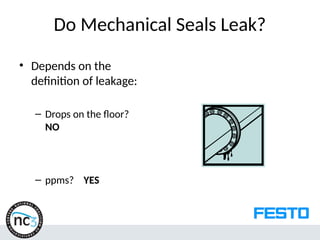
Do Mechanical SealsLeak?
• Depends on the
definition of leakage:
– Drops on the floor?
NO
– ppms? YES
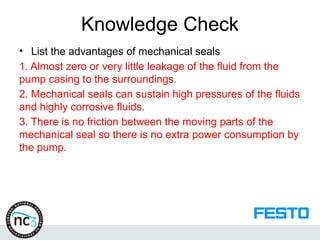
Knowledge Check
• Listthe advantages of mechanical seals
1. Almost zero or very little leakage of the fluid from the
pump casing to the surroundings.
2. Mechanical seals can sustain high pressures of the fluids
and highly corrosive fluids.
3. There is no friction between the moving parts of the
mechanical seal so there is no extra power consumption by
the pump.
120.
Knowledge Check
• Listthe shaft seal pre-inspection items.
The elastomer is not damaged.
The case is not damaged.
The garter spring is properly placed.
Wipe the seal and shaft of any debris.
The assembly lube is compatible with the lubricant in operation
The elastomer is of the proper specification
The lip seal is pointing in the correct direction
The shaft is free of defects
The bore is free of defects
Proper installation tools are used to avoid damaging seals
Equal pressure is applied during installation to ensure the seal is not
cocked
121.
Knowledge Check
• Whyis it important to lubricate a shaft seal
before installation? To prevent tearing or
sticking
• What is a lantern ring?
The lantern ring is used to distribute
cooling water to all packing rings as
well as keep the stuffing box clean of
containments