Download as PDF, PPTX
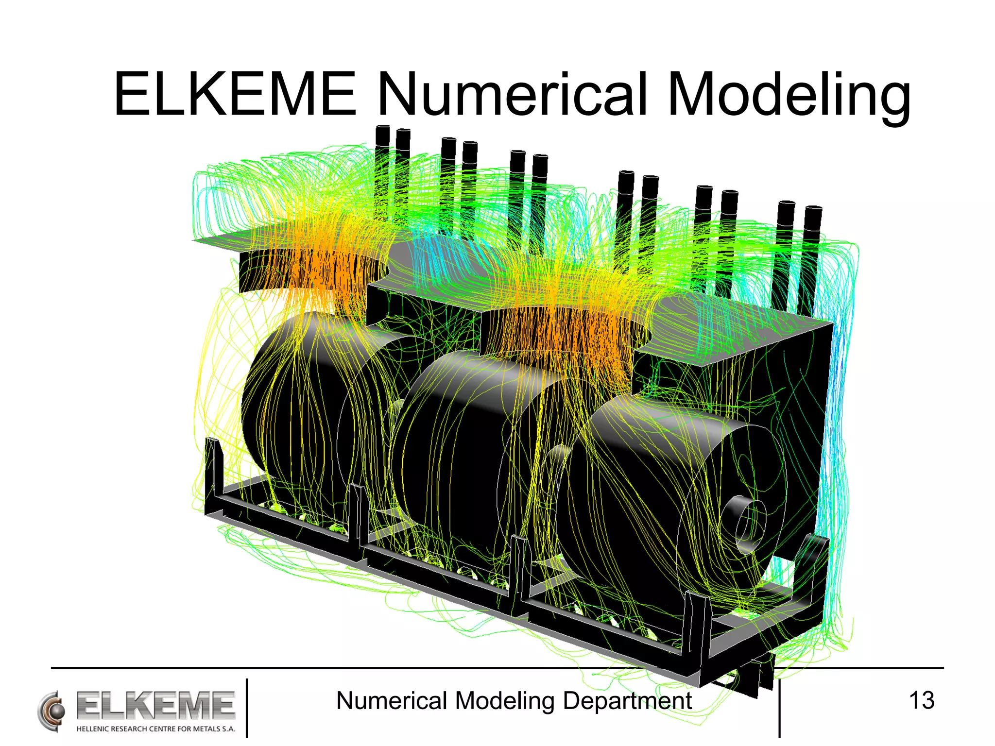
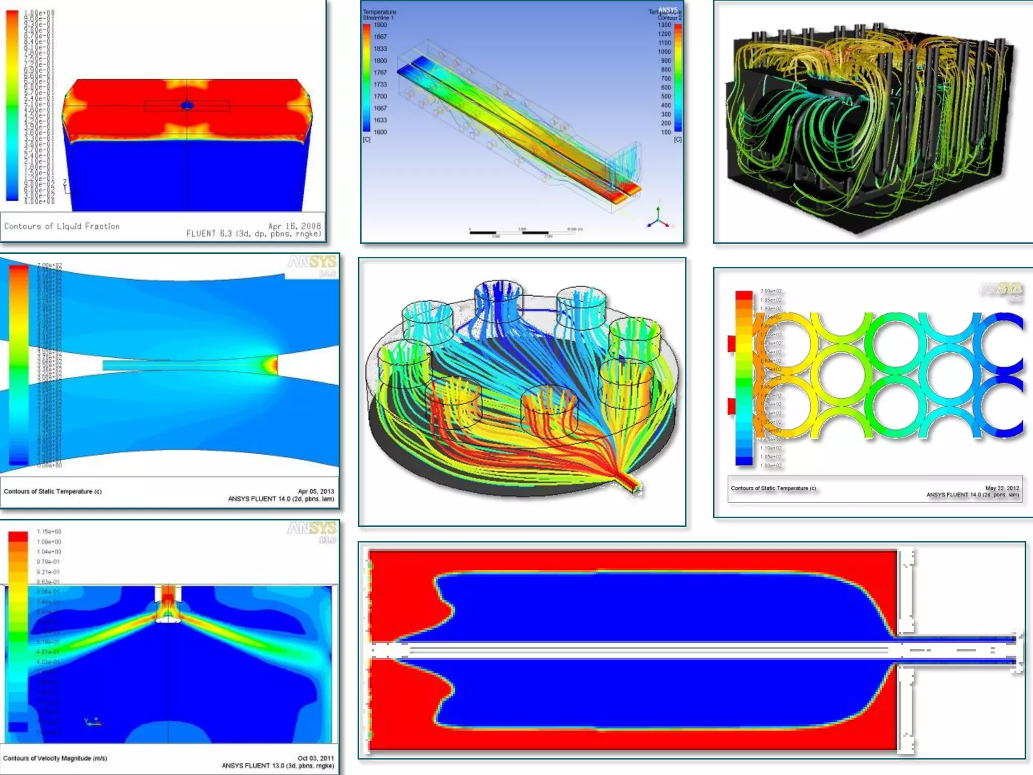
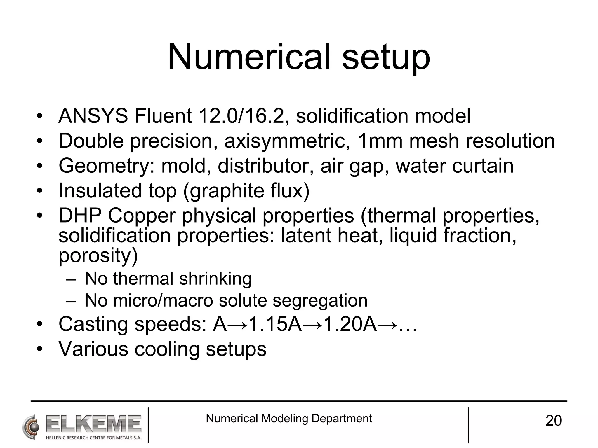
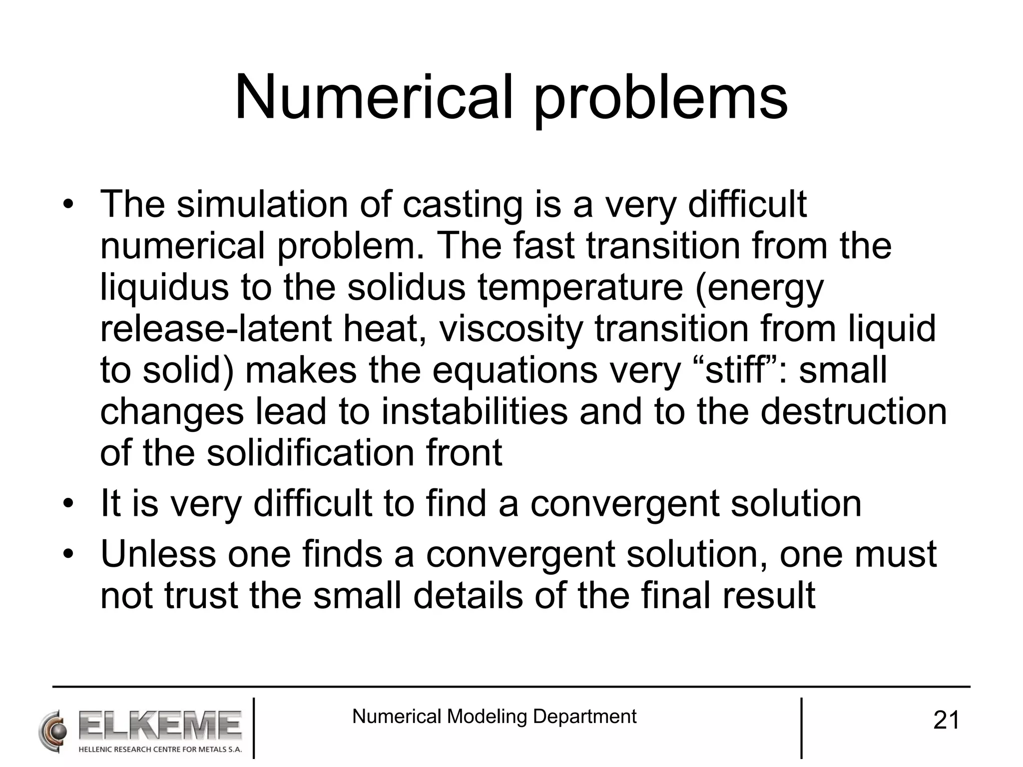
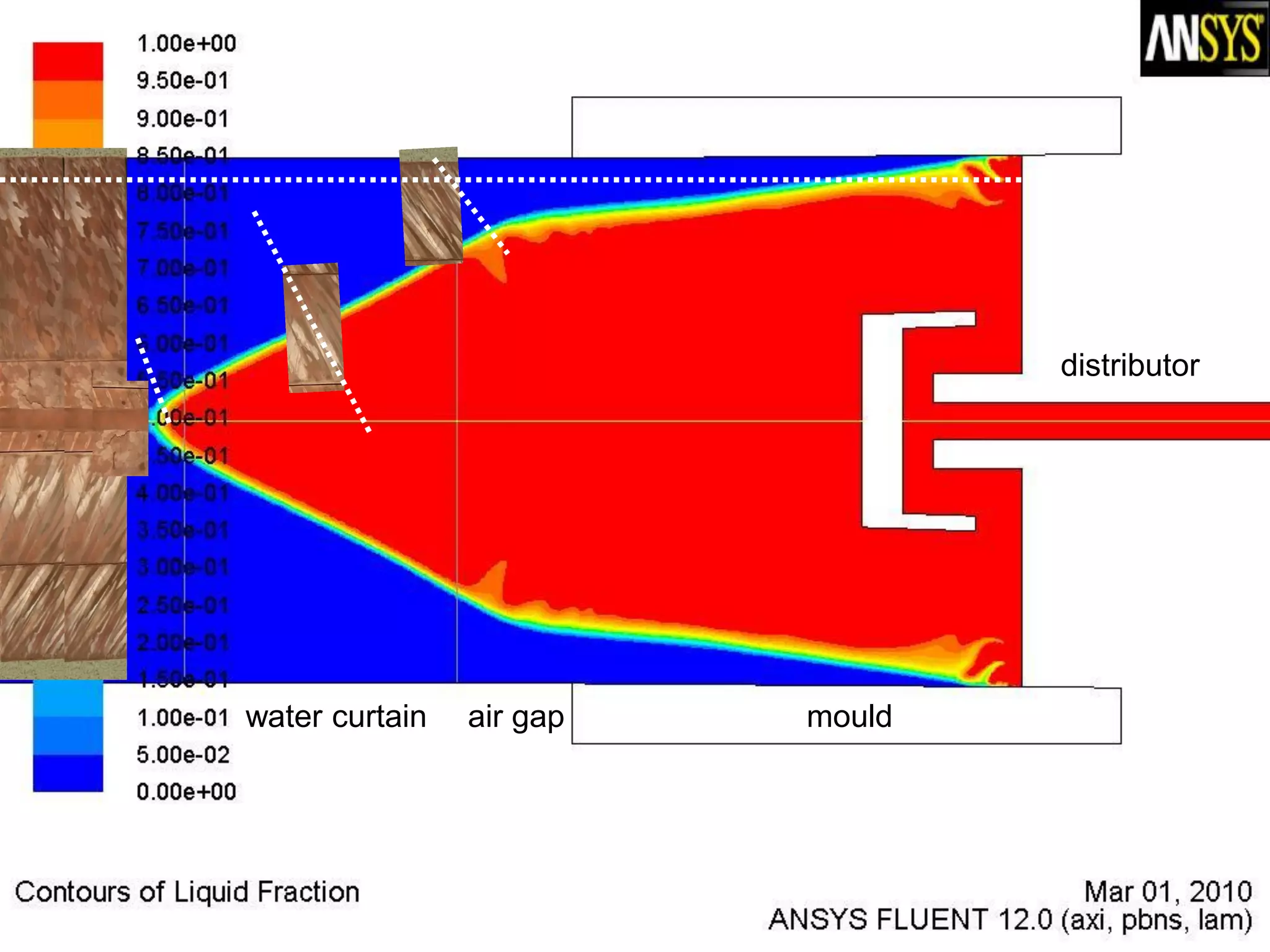
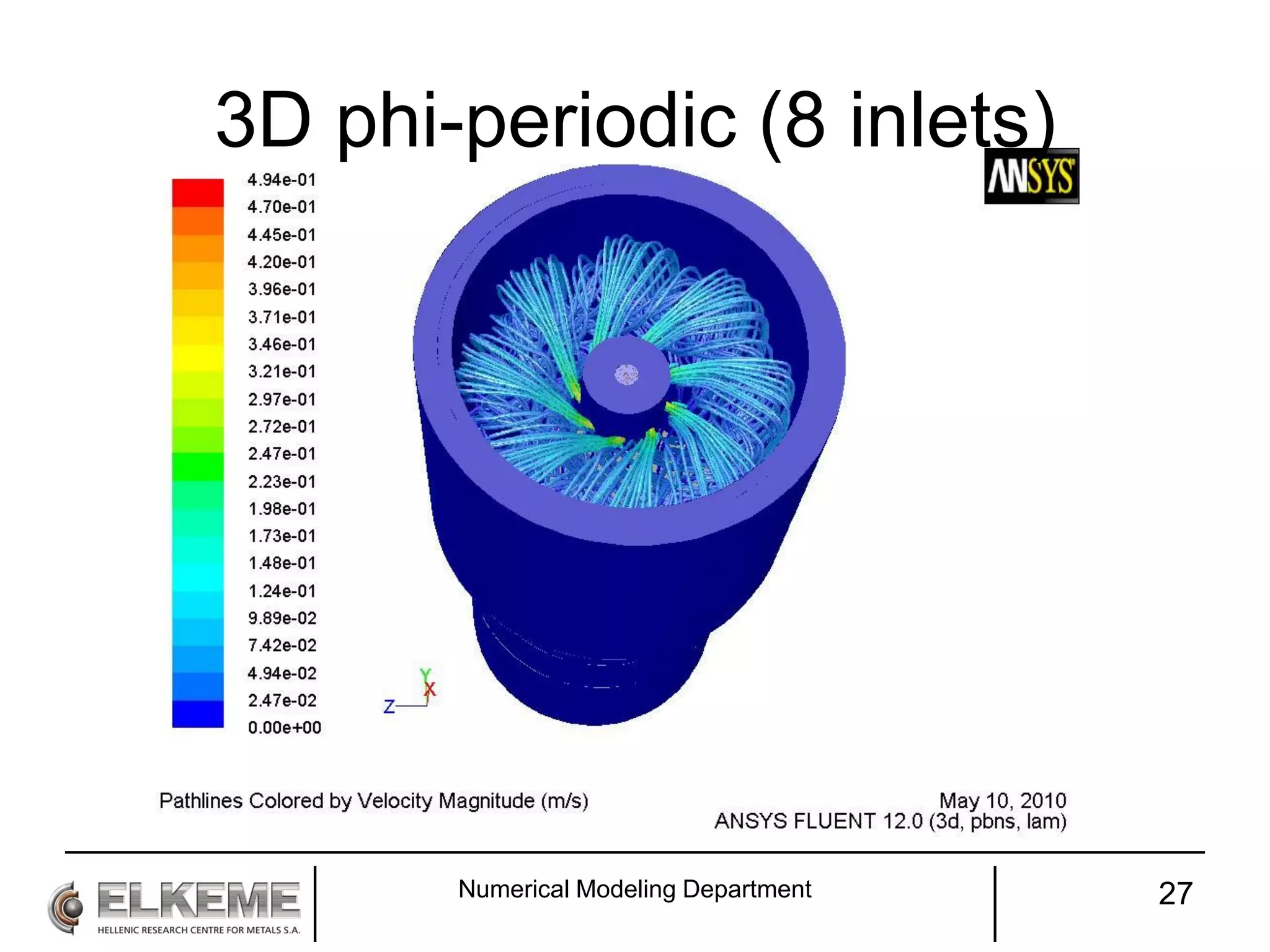
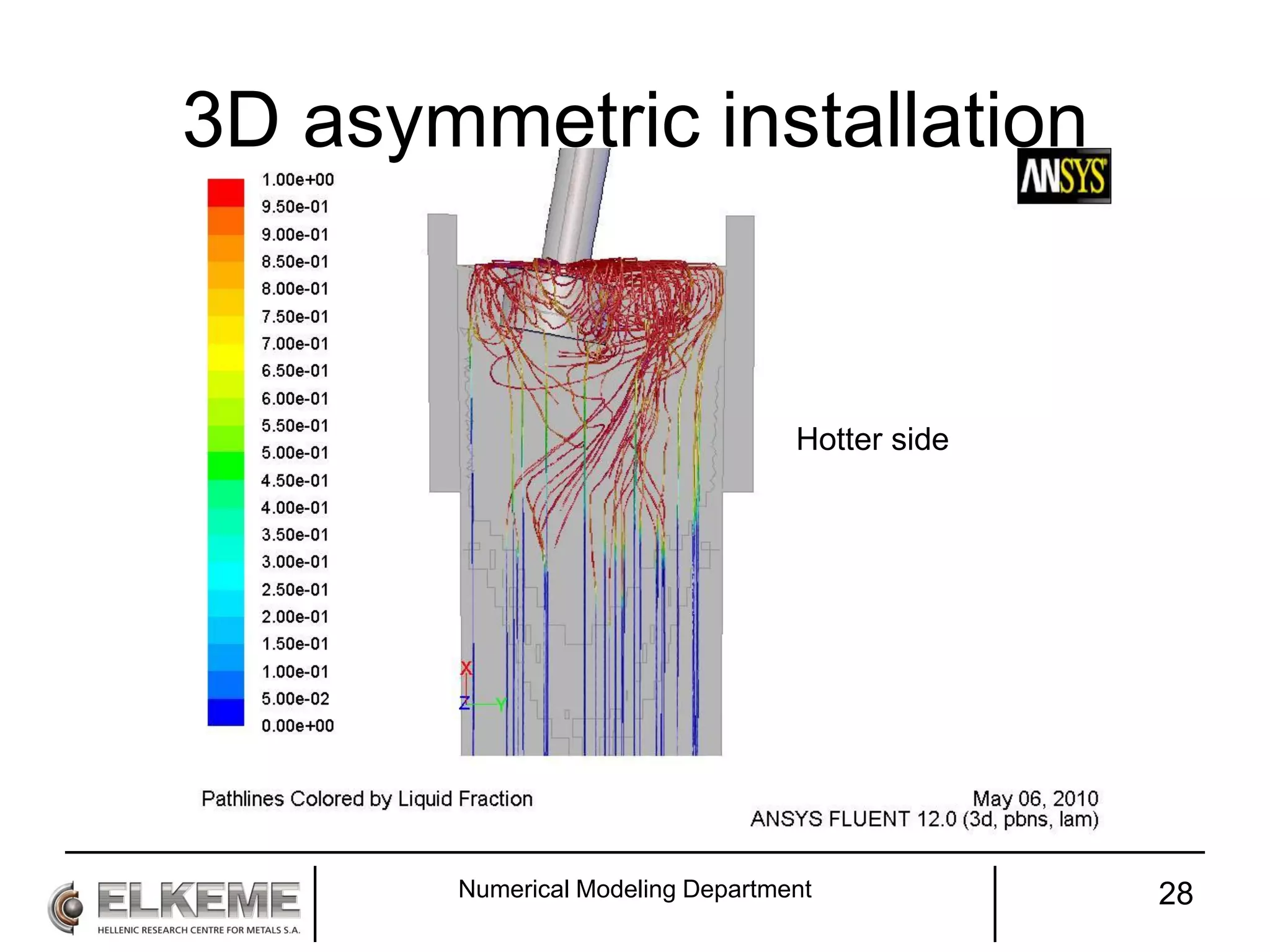
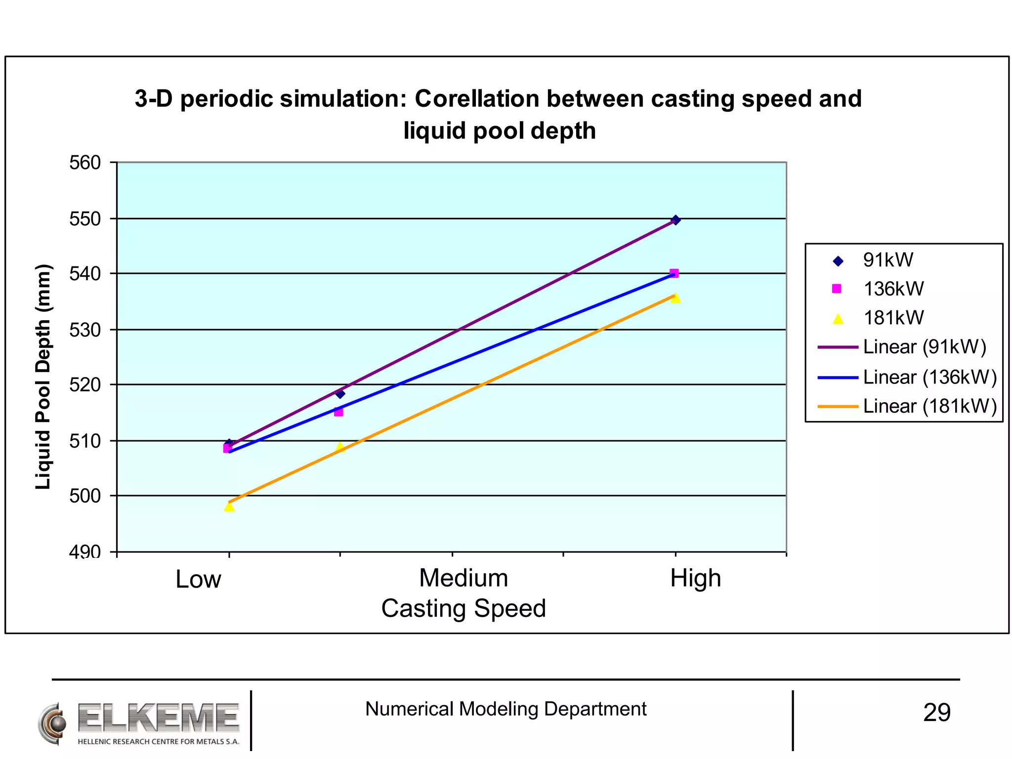
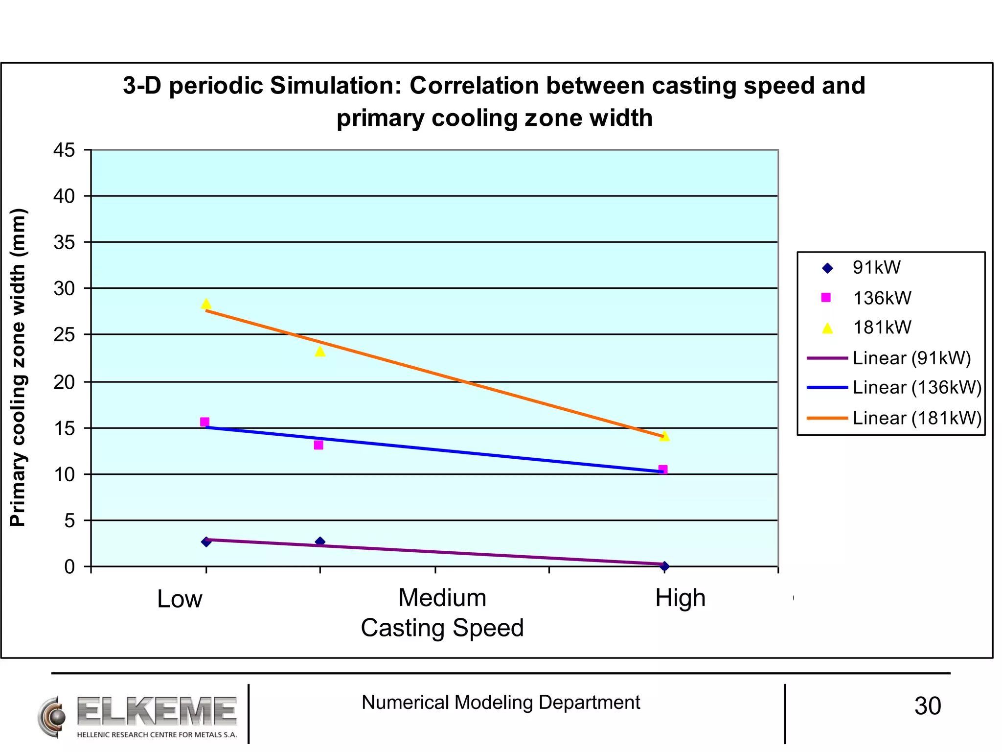
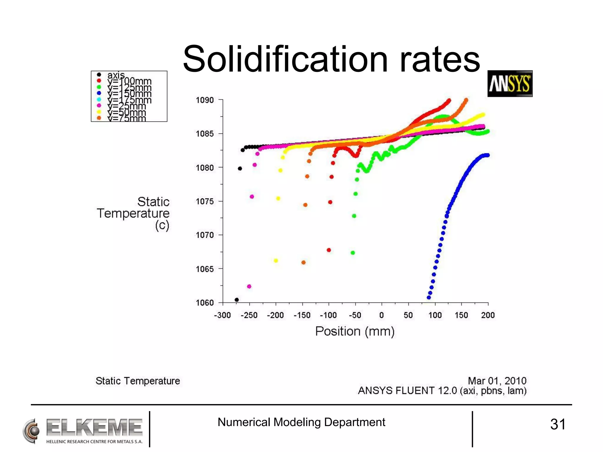
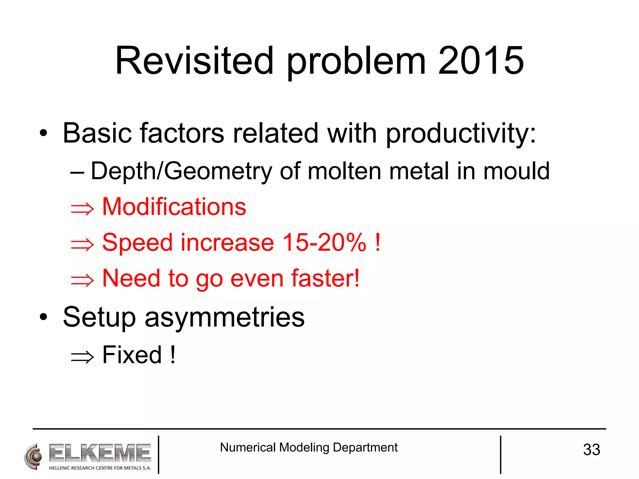

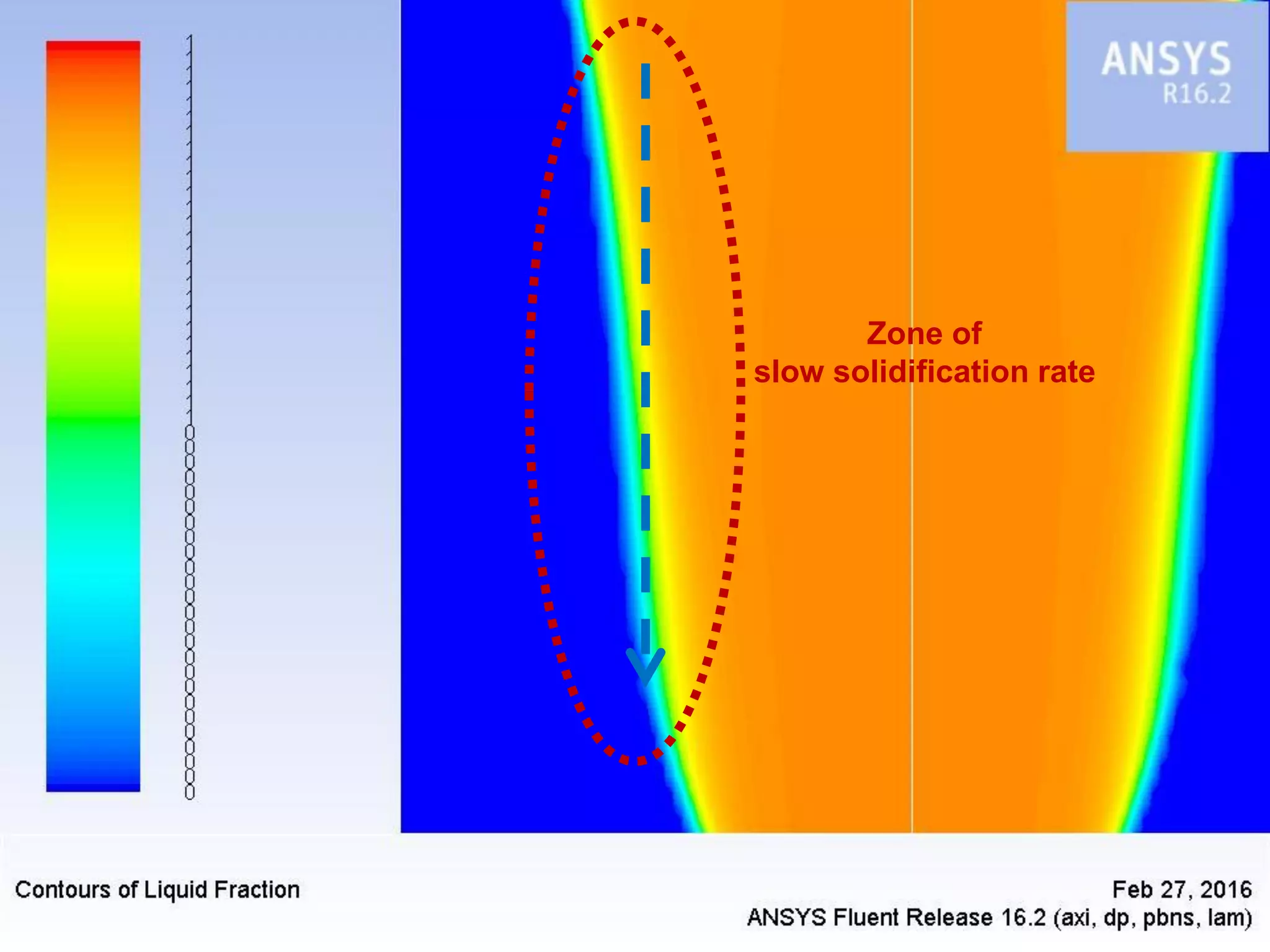
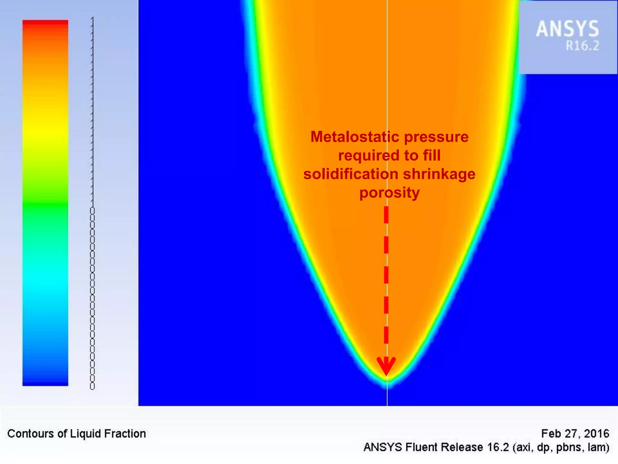
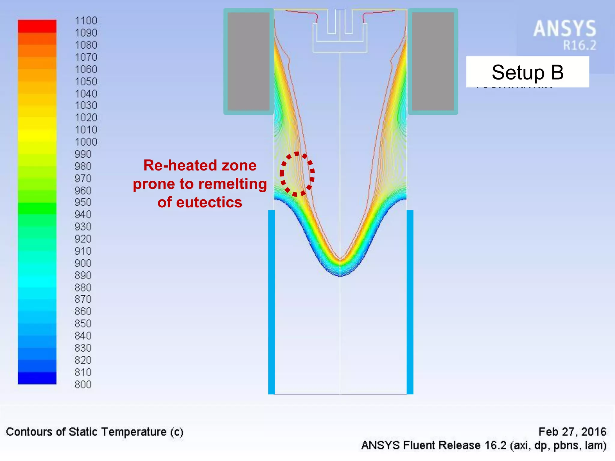
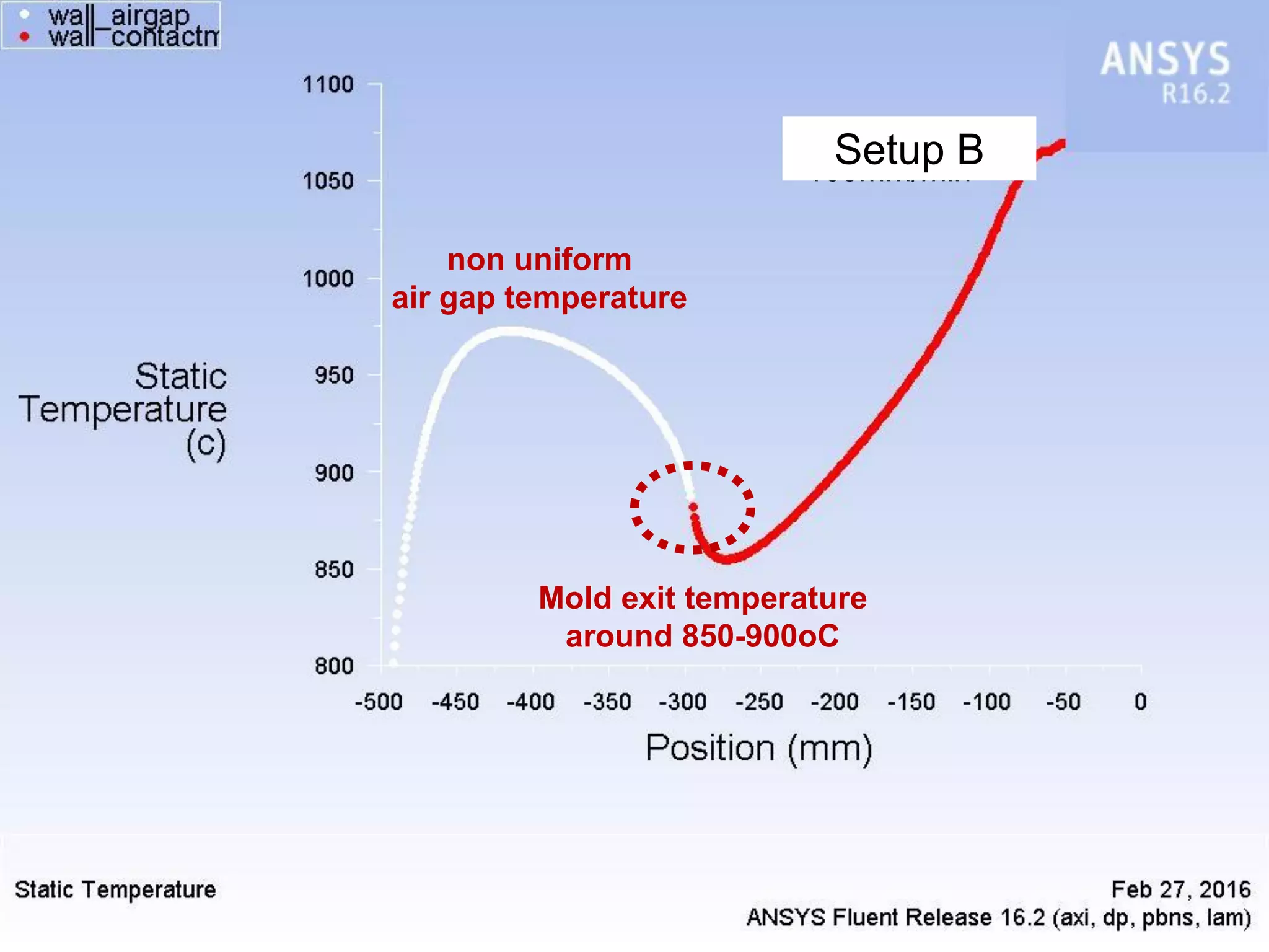

The document discusses the numerical modeling techniques used in copper billet casting at ELKEME, emphasizing the optimization of industrial processes, improvements in productivity, and technical collaborations. It highlights the challenges of simulating the casting process due to rapid phase transitions and the development of reliable numerical solutions. Recent findings show that modifications to casting setups can significantly enhance production speed and solidification front geometry.


