This document provides an overview of transport terminals and modal interchanges. It discusses the history of notable interchanges from the 20th century, challenges of integrating different transport systems, and examples of successful interchanges. It also examines studies and initiatives from the UK and international organizations that are working to improve interchange design. The bulk of the document consists of a taxonomy of different types of rail, airport, bus, and ferry terminals around the world, analyzing their layouts, operations, and interfaces between modes of transportation. Common standards, requirements, and trends for 21st century interchanges are also addressed.


![Transport
terminals
and
modal
interchanges
12
The
future
development
of
integrated
transport
2
1
4
3
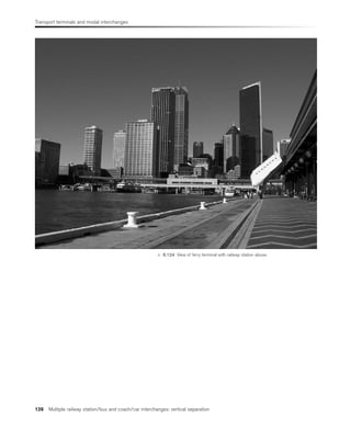
A 415
F
o
rm
e
r
A
3
3
8
B
4
0
1
7
Formerly
Garford
Drayton
Steventon
Grove
Marcham
Lyford
Abingdon
B
4
0
1
7
River
Ock
Existing railway
Frilford
A 4130
B 4016
A
34
(T
)
Ancient Woodland: Hutchins’s Copse
Milton
A 34 (T)
West Hanney
A 415
F
o
r
m
e
r
A
3
3
8
East Hanney
A 4130
Frilford bypass
B
D
iv
e
r
te
d
A
3
3
8
S
Projected Swindon link road
L
Area of High Landscape Value
Oxfordshire Structure Plan: 2001
P
Modified junction
D
iv
e
rt
e
d
A
3
3
8
Sewage Works
River Ock
D
A
A
Abingdon
Common
H E
Sewage Works
Y
new
u/g
ETL
V
I
N
C
Q
Z
Projected urban expansion
G
G
Relocated Golf Course
M2
500 0 1
1000 Metres 2
Kilometres
R
Relocated electical sub-station
Electricity
transmission
line
D
iv
e
rt
e
d
e
le
c
tr
ic
it
y
tr
a
n
s
m
is
s
io
n
li
n
e
C
F
F
F
M1
N
K
D
Scale 1:25 000 [at A3]
SEWAGE WORKS
HOLDING POND (2.25 million cubic m)
STAFF CAR PARKING
LONG-TERM PUBLIC CAR PARKING
DEVELOPMENT ZONE (230 Ha)
MAIN-LINE RAIL STATION
DEMOLITIONS
ACOUSTICAL BUNDS
RELOCATED VENN MILL:
WILDLIFE RESERVE CENTRE
K
L
M 1
M 2
N
P
Q
R
S
T
PASSENGER TERMINAL
PASSENGER RAIL STATION
SHORT-TERM PUBLIC CAR PARKING
WILDLIFE RESERVES WASHPLAINS (603 Ha)
SKY BRIDGE TO SATELLITES
SATELLITE
RESCUE FIRE FIGHTING STATION
SECURITY BASE
CONTROL TOWER AIRPORT CONTROL
AIR CARGO CENTRE
AIR CARGO RAIL STATION
AIR CARGO FREIGHT YARD
ENGINE TEST BAY
RESCUE TRAINING BASE
AIRCRAFT MAINTENANCE FACILITIES
POWER STATION
AIRPORT OPERATIONAL BASE
ANCILLARY FACILITIES
FUEL FARM
FUEL RAIL HEAD
A
B
C
D
E
F
G
H
I
J
U
V
W
X
Y
Z
LEGEND
A 415
M
a
r
c
h
a
m
B
y
p
a
s
s
D
U
T
D
D
D
*
*
Former
Golf Course D
X
W
F
J
J
G
NORTH
Copyright © 2003 Pleiade Associates Ltd 38 AA 28C v2A
3.3 London Oxford (LOX) satellite airport proposal, showing road and rail connections in detail (Courtesy of Pleiade Associates – see website
www.pleiade.org).](https://image.slidesharecdn.com/modelodetransportes-210910232552/85/Modelo-de-transportes-23-320.jpg)