1. MALLA REDDY ENGINEERING COLLEGEFOR WOMEN (AUTONOMOUS INSTITUION-UGC, GOVT. OF.INDIA )
DEPT.OF.ECE
DEVELOPMENT OF CLOUD BASED AUTOMATIC IRRIGATION SYSTEM USING IOT Page 1
CHAPTER-1
INTRODUCTION
The world population has seen an explosion with the advancements of the technology in
the last decades. As a result of this huge growth in the global population, the required
amount of food production is increased. In order to achieve this, new approaches such
as hydroponics, vertical farming, biotechnology, etc. are being applied. On the other
hand, development of methods for effective utilization of water resources is required
because shortage of water supplies, which is one of the leading consequences of
emerging climate change, is on the rise. Therefore, it becomes inevitable to include
automation and data processing methods in modern agricultural irrigation systems in
order to optimize the water usage. The studies in this area are generally based on
indirectly estimating the water need of plants and determining optimum duration of
irrigation accordingly. This is accomplished by using daily meteorological data, soil
moisture sensors , drainage lysimeters or evaporation pans. Majority of the automated
irrigation system studies use soil moisture data to determine the irrigation amount. For
example, the system developed by Gutiérrez et al. consists of soil moisture and
temperature sensors for data collection, a gateway unit for triggering actuators and
internet connection, and a web application for monitoring and programming of the
system . Their system was tested on a sage crop field and achieved water savings up to
90% compared with traditional irrigation practices. In another work, irrigation
scheduling for cucumber is performed through a standalone smart irrigation system with
ZigBee and GPRS communication capabilities. The system is programmed to keep the
soil moisture above 17%. Irrigation control is achieved through fuzzy logic method
which uses sensor data such as soil moisture, ambient temperature, solar radiation and
amount of water consumed. Drought stress and irrigation in potted plants are controlled
using an automated system proposed by Nemali and Iersel . The system consists of a
dielectric moisture sensor, data logger and solenoid valves. In this system volumetric
water content of a substrate is measured every 20 minutes and irrigation is controlled
according to this measurement. A solar powered and versatile drip irrigation system is
2. MALLA REDDY ENGINEERING COLLEGEFOR WOMEN (AUTONOMOUS INSTITUION-UGC, GOVT. OF.INDIA )
DEPT.OF.ECE
DEVELOPMENT OF CLOUD BASED AUTOMATIC IRRIGATION SYSTEM USING IOT Page 2
developed by Dursun and Özden . Their work involves generating a soil moisture
distribution map in an orchard. This is achieved by placing a number of soil moisture
sensors and an artificial neural network model. Using this system, unnecessary
irrigation is prevented and consequently water and energy consumption is reduced. In a
relatively recent work, computer and mobile modules are developed for facilitating
irrigation scheduling in the strawberry sector especially during the crop season . The
irrigation time within this system is calculated by using a previously built database
which contains various agricultural data proven to be affecting the irrigation
requirements. Even though there are various methods for irrigation automation in the
literature, systems using evaporation pans featuring cloud connection is not mentioned.
In evaporation pan applications, the pan is mounted in a greenhouse and the water level
in the pan is observed on a regular basis. At a given time interval, the water loss in the
soil is estimated according to the amount of water evaporated from the pan.
Conventionally, the water level in the pan is observed with bare eyes and the valves are
controlled manually. This method brings some disadvantages such as wasting time and
energy. In this study, a cloud-based automatic drip irrigation system that involves
measurement of the water level in a Class-A evaporation pan is proposed.
Measurements from a water levelsensor attached to the pan and an environmental sensor
are continuously transmitted to a microcontroller that controls the solenoid valves.
Using a GSM/GPRS module, the received sensor data and system status related
information are sent to a cloud server. Opening hour of the valves and irrigation
frequency are determined by the user. On the other hand, the duration of irrigation is
automatically calculated according to the water level decrement in the pan. Also, an
Android application is developed to monitor system status remotely and update the
water level information in the cloud
EXISTING SYSTEM
The project Crop monitoring system using tackle the problems of agricultural
sector regarding irrigation at times, motor pumps are left running for longer than what is
necessary because of the effort involved. In the existing system farmers have to travel to
fields often at odd hours just to switch on/off the motor due to erratic power supply.
Existing aids like auto starters are especially when a farmer in switching off. To
overcome the drawbacks of existing system like high cost, difficult in maintenance and
more wired connection, we introduce a new system which will have wireless connection
between server and nodes. We introduce a new design of embedded web server making
3. MALLA REDDY ENGINEERING COLLEGEFOR WOMEN (AUTONOMOUS INSTITUION-UGC, GOVT. OF.INDIA )
DEPT.OF.ECE
DEVELOPMENT OF CLOUD BASED AUTOMATIC IRRIGATION SYSTEM USING IOT Page 3
use of GSM network technology in this paper. Compared to the wired link web server
system, this system is characterized by having no wires between the web server and
terminal nodes. In proposed system the irrigation will take place only when there will be
intense requirement of water.
DISADVANTAGES
1. High cost and complex circuit.
2. Difficult to handle.
LITERATURE REVIEW
IN “T. OJHA, S. MISRA, N. SINGH RAGHUWANSHI,”WIRELESS SENSOR
NETWORKS FOR AGRICULTURE: THE STATE-OF-THE-ART IN PRACTICE
AND FUTURE CHALLENGES,” COMPUTERS AND ELECTRONICS IN
AGRICULTURE, VOL.1, NO. 18, PP. 66-84, SEPTEMBER 2015.” The advent of
Wireless Sensor Networks (WSNs) spurred a new direction of research in agricultural
and farming domain. In recent times, WSNs are widely applied in various agricultural
applications. In this paper, we review the potential WSN applications, and the specific
issues and challenges associated with deploying WSNs for improved farming. To focus
on the specific requirements, the devices, sensors and communication techniques
associated with WSNs in agricultural applications are analyzed comprehensively. We
present various case studies to thoroughly explore the existing solutions proposed in the
literature in various categories according to their design and implementation related
parameters. In this regard, the WSN deployments for various farming applications in the
Indian as well as global scenario are surveyed. We highlight the prospects and problems
of these solutions, while identifying the factors for improvement and future directions of
work using the new age technologies Modern day farming demands increased
production of food to accommodate the large global population. Towards this goal, new
technologies and solutions to enhance productivity. Moreover, the alarming climate
change and scarcity of water (Postel, 1999; Bouwer, 2000; Saleth and Dinar, 2000; Jury
and, 2007; Falloon and Betts, 2010; Mueller et al., 2012) demand new and improved
methods for modern agricultural fields. Consequently, the need for automation and
intelligent decision making is becoming more important to accomplish this mission (ur
Rehman et al., 2014; Suprem et al., 2013; Wang et al., 2006; Hart and Martinez, 2006).
4. MALLA REDDY ENGINEERING COLLEGEFOR WOMEN (AUTONOMOUS INSTITUION-UGC, GOVT. OF.INDIA )
DEPT.OF.ECE
DEVELOPMENT OF CLOUD BASED AUTOMATIC IRRIGATION SYSTEM USING IOT Page 4
In this regard, technologies such as ubiquitous computing (Burrell et al., 2004), wireless
ad-hoc and sensor networks (Diallo et al., 2015; Srbinovska et al., 2015; Zhao et al.,
2013; Karim et al., 2013; Zhang et al., 2013; Krishna et al., 2012; Zhang and Zhang,
2012; Misra et al., 2011; Mirabella and Brischetto, 2011; Lloret et al., 2011; Garcia et
al., 2010; Bri et al., 2009; Lloret et al., 2009; Lin et al., 2008; Wang et al., 2006), Radio
Frequency Identifier (RFID) (Ruiz-Garcia and Lunadei, 2011).A system developed for
malting barley cultivations in large areas of land allowed for the optimizing of irrigation
through decision support software and its integration with an infield wireless sensor
network (WSN) driving an irrigationmachine converted to make sprinkler nozzles
controllable. Communication between the sensor nodes and the data receiver is via the
Zigbee protocol , under the IEEE 802.15.4 WPAN. This receiver unit also has a duplex
communication link based on a cellular-Internet interface, using general packet radio
service (GPRS) protocol, which is a packet-oriented mobile data service used in 2G and
3G cellular global system for mobile communications (GSM). The Internet connection
allows the data inspection in real time on a website, where the soil-moisture and
temperature levels are graphically displayed through an application interface and stored
in a database server. This access also enables direct programming of scheduled
irrigation schemes and trigger values in the receiver according the crop growth and
season management. Because of its energy autonomy and low cost, the system has
potential use for organic crops, which are mainly located in geographically isolated
areas where the energy grid is far away
BLOCK DIAGRAM
NODE-MCU
POWER SUPPLY
TEMPERATURE
SOIL MOISTURE
R
E
L
A
Y
WATER
PUMP
5. MALLA REDDY ENGINEERING COLLEGEFOR WOMEN (AUTONOMOUS INSTITUION-UGC, GOVT. OF.INDIA )
DEPT.OF.ECE
DEVELOPMENT OF CLOUD BASED AUTOMATIC IRRIGATION SYSTEM USING IOT Page 5
CHAPTER 2
INTRODUCTION TO EMBEDDED SYSTEMS
Many embedded systems have substantially different design constraints than
desktop computing applications. No single characterization applies to the diverse
spectrum of embedded systems. However, some combination of cost pressure, long life-
cycle, real-time requirements, reliability requirements, and design culture dysfunction
can make it difficult to be successful applying traditional computer design
methodologies and tools to embedded applications. Embedded systems in many cases
must be optimizedfor life-cycle and business-driven factors rather than for maximum
computing throughput. There is currently little tool support for expanding embedded
computer design to the scope of holistic embedded system design. However, knowing
the strengths and weaknesses of current approaches can set expectations appropriately,
identify risk areas to tool adopters, and suggest ways in which tool builders can meet
industrial needs. If we look around us, today we see numerous appliances which we use
daily, be it our refrigerator, the microwave oven, cars, PDAs etc. Most appliances
today are powered by something beneath the sheath that makes them do what they do.
These are tiny microprocessors, which respond to various keystrokes or inputs. These
tiny microprocessors, working on basic assembly languages, are the heart of the
WATER LEVEL
6. MALLA REDDY ENGINEERING COLLEGEFOR WOMEN (AUTONOMOUS INSTITUION-UGC, GOVT. OF.INDIA )
DEPT.OF.ECE
DEVELOPMENT OF CLOUD BASED AUTOMATIC IRRIGATION SYSTEM USING IOT Page 6
appliances. We call them embedded systems. Of all the semiconductor industries, the
embedded systems market place is the most conservative, and engineering decisions
here usually lean towards established, low risk solutions. Welcome to the world of
embedded systems, of computers that will not look like computers and won’t function
like anything we are familiar with.
2.1 CLASSIFICATION
Embedded systems are divided into autonomous, realtime, networked & mobile
categories.
Autonomous systems
They function in standalone mode. Many embedded systems used for process
control in manufacturing units& automobiles fall under this category.
Real-time embedded systems
These are required to carry out specific tasks in a specified amount of time.
These systems are extensively used to carry out time critical tasks in process control.
Networked embedded systems
They monitor plant parameters such as temperature, pressure and humidity and
send the data over the network to a centralized system for on line monitoring.
Hardware
Good software design in embedded systems stems from a good understanding of
the hardware behind it. All embedded systems need a microprocessor, and the kinds of
microprocessors used in them are quite varied. A list of some of the common
microprocessors families are: ARM family, The Zilog Z8 family, Intel 8051/X86
family, Motorola 68K family and the power PC family. For processing of information
and execution of programs, embedded system incorporates microprocessor or micro-
controllerThis type of memory is called ROM. Embedded applications commonly
7. MALLA REDDY ENGINEERING COLLEGEFOR WOMEN (AUTONOMOUS INSTITUION-UGC, GOVT. OF.INDIA )
DEPT.OF.ECE
DEVELOPMENT OF CLOUD BASED AUTOMATIC IRRIGATION SYSTEM USING IOT Page 7
employ a special type of ROM that can be programmed or reprogrammed with the help
of special devices.
2.2 OTHER COMMON PARTS FOUND ON MANY EMBEDDED
SYSTEMS
UART& RS232
PLD
ASIC’s& FPGA’s
Watch dog timer etc.
2.3 DESIGN PROCESS
Embedded system design is a quantitative job. The pillars of the system design
methodology are the separation between function and architecture, is an essential step
from conception to implementation. In recent past, the search and industrial community
has paid significant attention to the topic of hardware-software (HW/SW) code sign and
has tackled the problem of coordinating the design of the parts to be implemented as
software and the parts to be implemented as hardware avoiding the HW/SW integration
problem marred the electronics system industry so long Hardware can be simulated at
different levels such as electrical circuits, logic gates, RTL e.t.c. using VHDL
description. In some environments software development tools can be coupled with
hardware simulators, while in others the software is executed on the simulated
hardware. The later approach is feasible only for small parts of embedded systems.
Design of an embedded system using Intel’s 80C188EB chip is shown in the figure.
Inorder to reduce complexity, the design process is divided in four major steps:
specification, system synthesis, implementation synthesis and performance evaluation
of the prototype.
2.3.1 SPECIFICATION
During this part of the design process, the informal requirements of the analysis
are transformed to formal specification using SDL.
2.3.2 SYSTEM-SYNTHESIS
For performing an automatic HW/SW partitioning, the system synthesis step
8. MALLA REDDY ENGINEERING COLLEGEFOR WOMEN (AUTONOMOUS INSTITUION-UGC, GOVT. OF.INDIA )
DEPT.OF.ECE
DEVELOPMENT OF CLOUD BASED AUTOMATIC IRRIGATION SYSTEM USING IOT Page 8
translates the SDL specification to an internal system model switch contains problem
graph& architecture graph. After system synthesis, the resulting system model is
translated back to SDL.
2.3.3 IMPLEMENTATION-SYNTHESIS
SDL specification is then translated into conventional implementation languages
such as VHDL for hardware modules and C for software parts of the system.
2.3.4 PROTOTYPING
On a prototyping platform, the implementation of the system under development
is executed with the software parts running on multiprocessor unit and the hardware part
running on a FPGA board known as phoenix, prototype hardware for Embedded
Network Interconnect Accelerators.
2.3.5 APPLICATIONS
Embedded systems are finding their way into robotic toys and electronic pets,
intelligent cars and remote controllable home appliances. All the major toy makers
across the world have been coming out with advanced interactive toys that can become
our friends for life. ‘Furby’ and ‘AIBO’ are good examples at this kind. Furbies have a
distinct life cycle just like human beings, starting from being a baby and growing to an
adult one IBM is developing an air conditioner that we can control over the net.
Embedded systems cover such a broad range of products that generalization is difficult.
Here are some broad categories.
9. MALLA REDDY ENGINEERING COLLEGEFOR WOMEN (AUTONOMOUS INSTITUION-UGC, GOVT. OF.INDIA )
DEPT.OF.ECE
DEVELOPMENT OF CLOUD BASED AUTOMATIC IRRIGATION SYSTEM USING IOT Page 9
Fig 2.1: Embedded Development Life Cycle
Aerospace and defence electronics: Fire control, radar, robotics/sensors, sonar.
Automotive: Auto body electronics, auto power train, auto safety, car
information systems.
Broadcast & entertainment: Analog and digital sound products, cameras,
DVDs, Set top boxes, virtual reality systems, graphic products.
Requirement
analysis
Specification
System
architecture
H/w design S/w design
S/w
implementation
H/w testing S/w testing
System integration
H/w
implementation
Systemvalidation
Operation
Maintenance
Evolution
10. MALLA REDDY ENGINEERING COLLEGEFOR WOMEN (AUTONOMOUS INSTITUION-UGC, GOVT. OF.INDIA )
DEPT.OF.ECE
DEVELOPMENT OF CLOUD BASED AUTOMATIC IRRIGATION SYSTEM USING IOT Page 10
Consumer/internet appliances: Business handheld computers, business
network computers/terminals, electronic books, internet smart handheld devices,
PDAs.
Data communications: Analog modems, ATM switches, cable modems, XDSL
modems, Ethernet switches, concentrators.
Digital imaging: Copiers, digital still cameras, Fax machines, printers, scanners.
Industrial measurement and control: Hydro electric utility research &
management traffic management systems, train marine vessel management
systems.
Medical electronics: Diagnostic devices, real time medical imaging systems,
surgical devices, critical care systems.
Server I/O: Embedded servers, enterprise PC servers, PCI LAN/NIC
controllers, RAID devices, SCSI devices.
Telecommunications: ATM communication products, base stations, networking
switches, SONET/SDH cross connect, multiplexer.
Mobile data infrastructures: Mobile data terminals, pagers, VSATs, Wireless
LANs, Wireless phones.
11. MALLA REDDY ENGINEERING COLLEGEFOR WOMEN (AUTONOMOUS INSTITUION-UGC, GOVT. OF.INDIA )
DEPT.OF.ECE
DEVELOPMENT OF CLOUD BASED AUTOMATIC IRRIGATION SYSTEM USING IOT Page 11
CHAPTER 3
NODE-MCU
NODE MCU:
Node-MCU is a low-cost open source IoT platform. It initially included firmware which
runs on the ESP8266 Wi-Fi SoC from Espressif Systems, and hardware which was
based on the ESP-12 module.[6][7] Later, support for the ESP32 32-bit MCU was
added
3.1 OVERVIEW:
Node MCU is an open source firmware for which open source prototyping board
designs are available. The name "Node MCU" combines "node" and "MCU" (micro-
controller unit).[8]. The term "Node MCU" strictly speaking refers to the firmware
rather than the associated development kits.[citation needed]
Both the firmware and prototyping board designs are open source.
The firmware uses the Lua scripting language. The firmware is based on the eLua
project, and built on the Espressif Non-OS SDK for ESP8266. It uses many open source
projects, such as lua-cjson[10] and SPIFFS.[11] Due to resource constraints, users need
to select the modules relevant for their project and build a firmware tailored to their
needs. Support for the 32-bit ESP32 has also been implemented.
The prototyping hardware typically used is a circuit board functioning as a dual in-line
package (DIP) which integrates a USB controller with a smaller surface-mounted board
containing the MCU and antenna. The choice of the DIP format allows for easy
prototyping on breadboards. The design was initially was based on the ESP-12 module
of the ESP8266, which is a Wi-Fi SoC integrated with a TensilicaXtensa LX106 core,
widely used in IoT applications
12. MALLA REDDY ENGINEERING COLLEGEFOR WOMEN (AUTONOMOUS INSTITUION-UGC, GOVT. OF.INDIA )
DEPT.OF.ECE
DEVELOPMENT OF CLOUD BASED AUTOMATIC IRRIGATION SYSTEM USING IOT Page 12
3.2 HISTORY:
Node MCU was created shortly after the ESP8266 came out. On December 30, 2013,
Espressif Systems[6] began production of the ESP8266.[12] Node MCU started on 13
Oct 2014, when Hong committed the first file of Node MCU-firmware to GitHub.[13]
Two months later, the project expanded to include an open-hardware platform when
developer Huang R committed the gerber file of an ESP8266 board, named devkit
v0.9.[14] Later that month, Tuan PM ported MQTT client library from Contiki to the
ESP8266 SoC platform,[15] and committed to Node MCU project, then Node MCU
was able to support the MQTT IoT protocol, using Lua to access the MQTT broker.
Another important update was made on 30 Jan 2015, when Devsaurus ported the
u8glib[16] to the Node MCU project,[17] enabling Node MCU to easily drive LCD,
Screen, OLED, even VGA displays. In the summer of 2015 the original creators
abandoned the firmware project and a group of independent contributors took over. By
the summer of 2016 the Node MCU included more than 40 different modules.
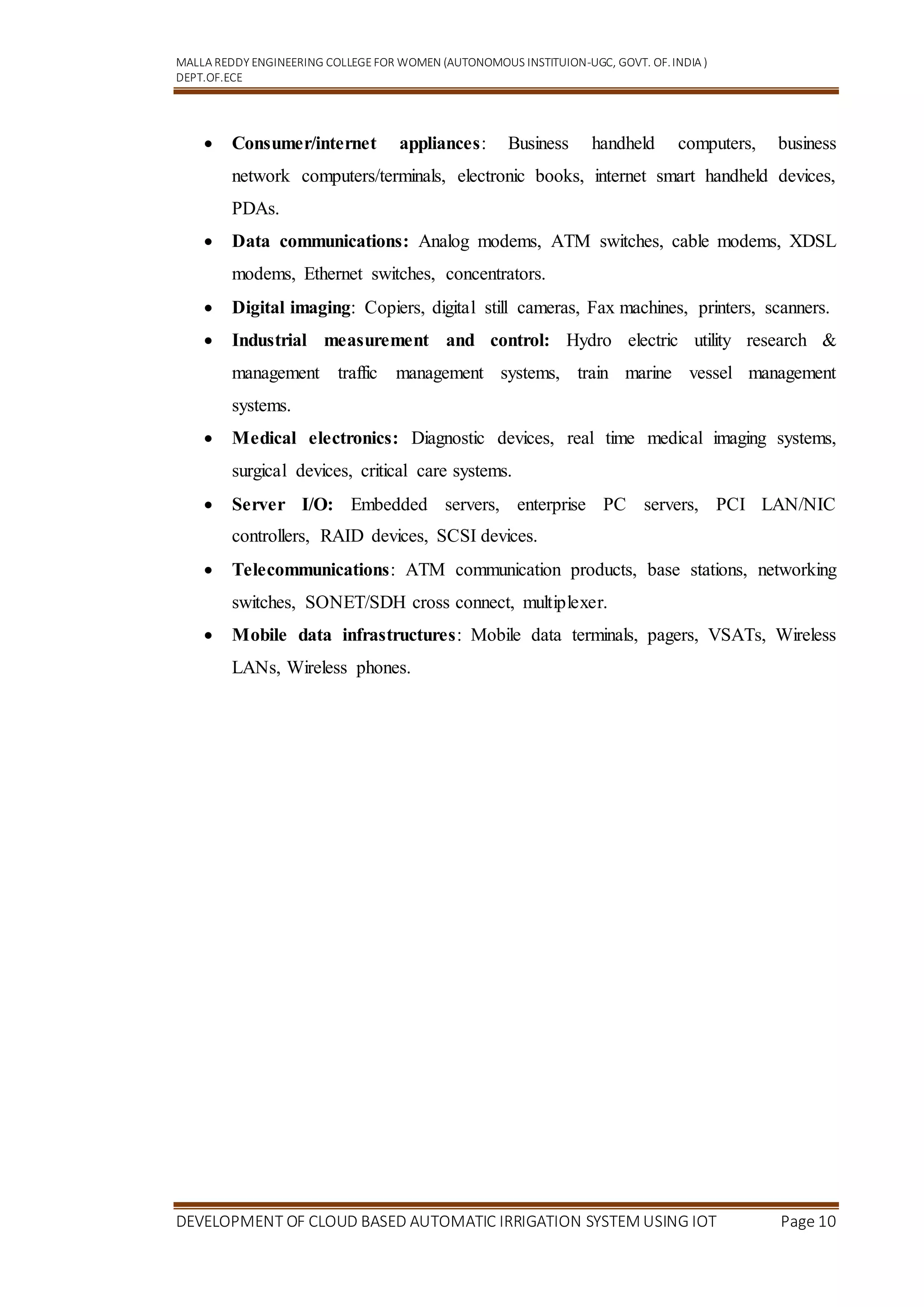
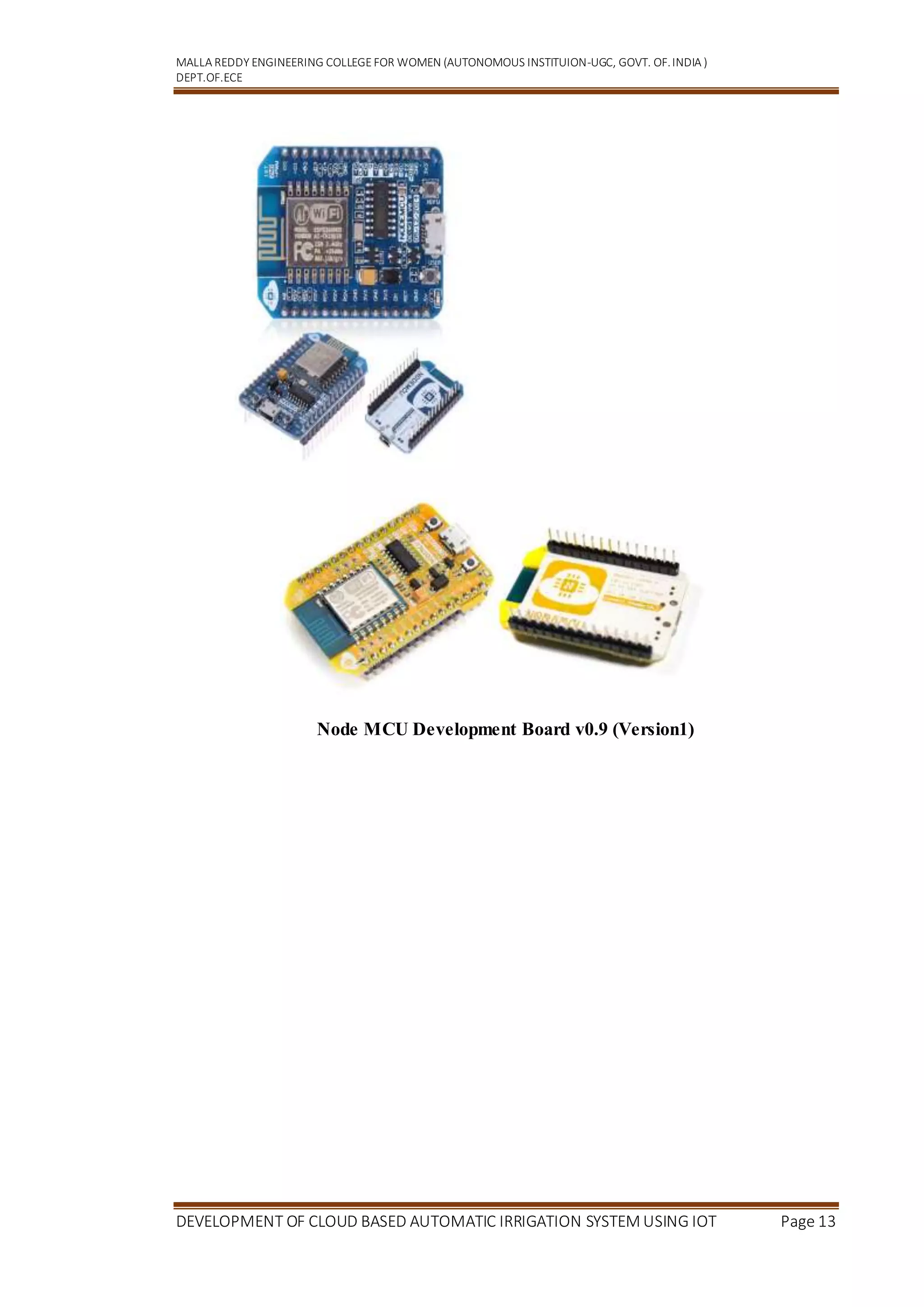
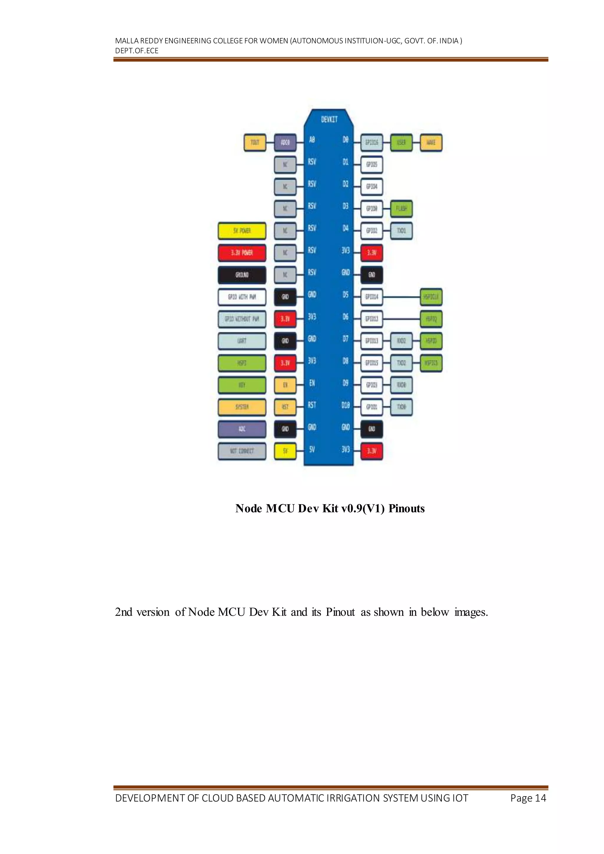
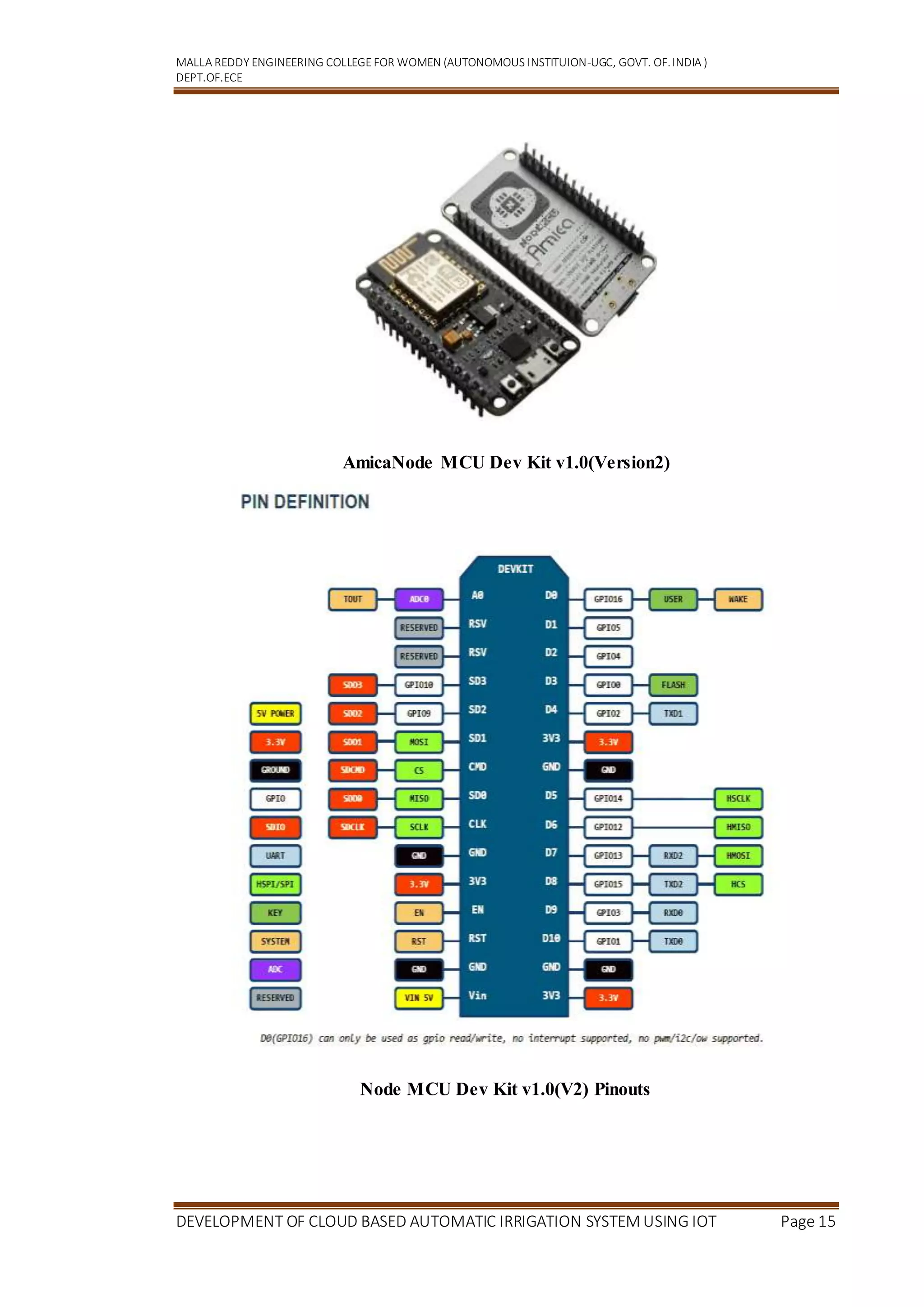
3.3 INTRODUCTION TO NODE MCU:
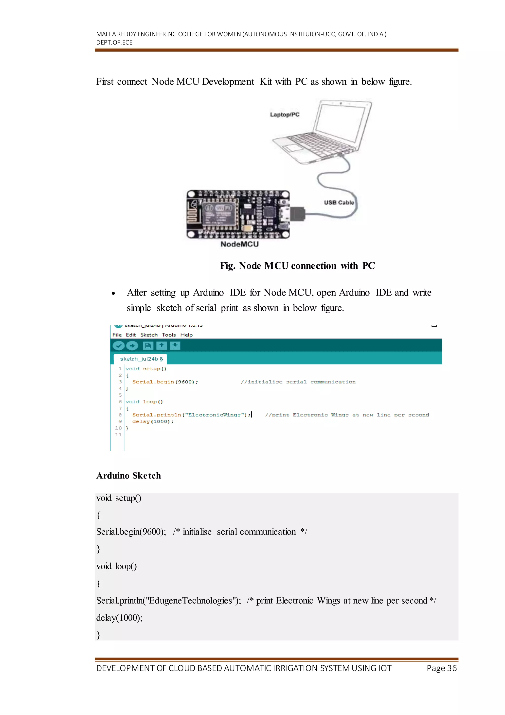
Node MCU is an open source LUA based firmware developed for ESP8266 wifi chip.
Node MCU Development Kit/Board consist of ESP8266 wifi chip. ESP8266 chip has
GPIO pins, serial communication protocol, etc. features on it.ESP8266 is a low-
cost Wi-Fi chip developed by Espressif Systems with TCP/IP protocol. For more
information about ESP8266, you can refer ESP8266 WiFi Module.The features of
ESP8266 are extracted on Node MCU Development board. Node MCU (LUA based
firmware) with Development board/kit that consist of ESP8266 (wifi enabled chip) chip
combines Node MCU Development board which make it stand-alone device in IoT
applications.Let’s see 1st version of Node MCU Dev Kit and its pinout as shown in
below images.
13. MALLA REDDY ENGINEERING COLLEGEFOR WOMEN (AUTONOMOUS INSTITUION-UGC, GOVT. OF.INDIA )
DEPT.OF.ECE
DEVELOPMENT OF CLOUD BASED AUTOMATIC IRRIGATION SYSTEM USING IOT Page 13
Node MCU Development Board v0.9 (Version1)
14. MALLA REDDY ENGINEERING COLLEGEFOR WOMEN (AUTONOMOUS INSTITUION-UGC, GOVT. OF.INDIA )
DEPT.OF.ECE
DEVELOPMENT OF CLOUD BASED AUTOMATIC IRRIGATION SYSTEM USING IOT Page 14
Node MCU Dev Kit v0.9(V1) Pinouts
2nd version of Node MCU Dev Kit and its Pinout as shown in below images.
15. MALLA REDDY ENGINEERING COLLEGEFOR WOMEN (AUTONOMOUS INSTITUION-UGC, GOVT. OF.INDIA )
DEPT.OF.ECE
DEVELOPMENT OF CLOUD BASED AUTOMATIC IRRIGATION SYSTEM USING IOT Page 15
AmicaNode MCU Dev Kit v1.0(Version2)
Node MCU Dev Kit v1.0(V2) Pinouts
16. MALLA REDDY ENGINEERING COLLEGEFOR WOMEN (AUTONOMOUS INSTITUION-UGC, GOVT. OF.INDIA )
DEPT.OF.ECE
DEVELOPMENT OF CLOUD BASED AUTOMATIC IRRIGATION SYSTEM USING IOT Page 16
Node MCU Dev Kit v1.0 pin descriptions
GPIO (General Purpose Input Output) Pins:
Node MCU has general purpose input output pins on its board as shown in above pinout
diagram. We can make it digital high/low and control things like LED or switch on it.
Also, we can generate PWM signal on these GPIO pins.
For more information about Node MCU GPIO
For more information about Node MCU PWM
ADC (Analog to Digital Converter) channel (A0):
Node MCU has one ADC channel/pin on its board.
For more information about Node MCU ADC
SPI (Serial Peripheral Interface) Pins:
Node MCU based ESP8266 has Hardware SPI (HSPI) with four pins available for SPI
communication. It also has SPI pins for Quad-SPI communication. With this SPI
interface, we can connect any SPI enabled device with Node MCU and make
communication possible with it. For more information about Node MCU SPI
I2C (Inter-Integrated Circuit) Pins:
Node MCU has I2C functionality support on ESP8266 GPIO pins. Due to internal
functionality on ESP-12E we cannot use all its GPIOs for I2C functionality. So, do tests
before using any GPIO for I2C applications. For more information about Node MCU
I2C
UART (Universal Asynchronous Receiver Transmitter) Pins:
Node MCU based ESP8266 has two UART interfaces,UART0 and UART1. Since UART0
(RXD0 & TXD0) is used to upload firmware/codes to board, we can’t use them in applications
while uploading firmware/codes
17. MALLA REDDY ENGINEERING COLLEGEFOR WOMEN (AUTONOMOUS INSTITUION-UGC, GOVT. OF.INDIA )
DEPT.OF.ECE
DEVELOPMENT OF CLOUD BASED AUTOMATIC IRRIGATION SYSTEM USING IOT Page 17
CHAPTER 4
HARDWARE COMPONENTS
4.1 REGULATED POWER SUPPLY:
Introduction: Power supplyis a supply ofelectrical power. A device or system that
supplies electrical or other types ofenergy to an output load or group of loads is called
a power supply unit or PSU. The term is most commonly applied to electrical energy
supplies, less often to mechanical ones, and rarely to others. A power supply may
include a power distribution system as well as primary or secondary sources of energy
such as
Conversion of one form of electrical power to another desired form and voltage,
typically involving converting AC line voltage to a well-regulated lower-
voltage DC for electronic devices. Low voltage, low power DC power supply units
are commonly integrated with the devices they supply, such as computers and
household electronics.
Batteries.
Chemical fuel cells and other forms of energy storage systems.
Solar power.
Generators or alternators.
Block Diagram:
Fig .Regulated Power Supply
18. MALLA REDDY ENGINEERING COLLEGEFOR WOMEN (AUTONOMOUS INSTITUION-UGC, GOVT. OF.INDIA )
DEPT.OF.ECE
DEVELOPMENT OF CLOUD BASED AUTOMATIC IRRIGATION SYSTEM USING IOT Page 18
The basic circuit diagram of a regulated power supply (DC O/P) with led connected as
load is shown in fig:
Fig .Circuit diagram of Regulated Power Supply with Led
connection
The components mainly used in above figure are
230V AC MAINS
TRANSFORMER
BRIDGE RECTIFIER(DIODES)
CAPACITOR
VOLTAGE REGULATOR(IC 7805)
RESISTOR
LED(LIGHT EMITTING DIODE)
The detailed explanation of each and every component mentioned above is as
follows: Step 1: Transformation: The process of transforming energy from one
device to another is called transformation. For transforming energy we use transformers.
4.2 Transformers:
A transformer is a device that transfers electrical energy from one circuit to
another through inductively coupled conductors without changing its frequency. A
varying current in the first or primary winding creates a varying magnetic flux in the
19. MALLA REDDY ENGINEERING COLLEGEFOR WOMEN (AUTONOMOUS INSTITUION-UGC, GOVT. OF.INDIA )
DEPT.OF.ECE
DEVELOPMENT OF CLOUD BASED AUTOMATIC IRRIGATION SYSTEM USING IOT Page 19
transformer's core, and thus a varying magnetic field through the secondary winding.
This varying magnetic field induces a varying electromotive force (EMF) or "voltage"
in the secondary winding. This effect is called mutual induction.
If another coil is placed adjacent to the first coil then, as the field moves out or in, the
moving lines of force will "cut" the turns of the second coil. As it does this, a voltage is
induced in the second coil. With the 50 Hz AC mains supply, this will happen 50 times
a second. This is called MUTUAL INDUCTION and forms the basis of the transformer.
The input coil is called the PRIMARY WINDING; the output coil is the
SECONDARY WINDING. Fig: 3.3.4 shows step-down transformer.
Fig 3.3.3: Step-Down Transformer
The voltage induced in the secondary is determined by the TURNS RATIO.
For example, if the secondary has half the primary turns; the secondary will
have half the primary voltage. To aid magnetic coupling between primary and
secondary, the coils are wound on a metal CORE. Since the primary would induce
power, called EDDY CURRENTS, into this core, the core is LAMINATED. This
means that it is made up from metal sheets insulated from each other. Transformers to
work at higher frequencies have an iron dust core or no core at all. Some transformers
have an electrostatic screen between primary and secondary. This is to prevent some
types of interference being fed from the equipment down into the mains supply, or in
the other direction. Transformers are sometimes used for IMPEDANCE MATCHING.
20. MALLA REDDY ENGINEERING COLLEGEFOR WOMEN (AUTONOMOUS INSTITUION-UGC, GOVT. OF.INDIA )
DEPT.OF.ECE
DEVELOPMENT OF CLOUD BASED AUTOMATIC IRRIGATION SYSTEM USING IOT Page 20
4.3 Battery power supply:
A battery is a type of linear power supply that offers benefits that traditional
line-operated power supplies lack: mobility, portability and reliability. A battery
consists of multiple electrochemical cells connected to provide the voltage desired. Fig:
3.3.4 shows Hi-Watt 9V battery
Fig : Hi-Watt 9V Battery
The most commonly used dry-cell battery is the carbon-zinc dry cell
battery. Dry-cell batteries are made by stacking a carbon plate, a layer of electrolyte
paste, and a zinc plate alternately until the desired total voltage is achieved. The most
common dry-cell batteries have one of the following voltages: 1.5, 3, 6, 9, 22.5, 45, and
90. During the discharge of a carbon-zinc battery, the zinc metal is converted to a zinc
salt in the electrolyte, and magnesium dioxide is reduced at the carbon electrode. These
actions establish a voltage of approximately 1.5 V.
Fig : Pencil Battery of 1.5V
Step 2: Rectification
21. MALLA REDDY ENGINEERING COLLEGEFOR WOMEN (AUTONOMOUS INSTITUION-UGC, GOVT. OF.INDIA )
DEPT.OF.ECE
DEVELOPMENT OF CLOUD BASED AUTOMATIC IRRIGATION SYSTEM USING IOT Page 21
The process of converting an alternating current to a pulsating direct current is
called as rectification. For rectification purpose we use rectifiers.
4.4 Rectifiers:
A rectifier is an electrical device that converts alternating current (AC) to direct
current (DC), a process known as rectification. Rectifiers have many uses including as
components of power supplies and as detectors of radio signals. Rectifiers may be made
of solid-state diodes, vacuum tube diodes, mercury arc valves, and other components.A
device that it can perform the opposite function (converting DC to AC) is known as an
inverter.
Bridge full wave rectifier:
The Bridge rectifier circuit is shown in figure, which converts an ac voltage to dc
voltage using both half cycles of the input ac voltage. The Bridge rectifier circuit is
shown in the figure. The circuit has four diodes connected to form a bridge. The ac
input voltage is applied to the diagonally opposite ends of the bridge. The load
resistance is connected between the other two ends of the bridge.For the positive half
cycle of the input ac voltage, diodes D1 and D3 conduct, whereas diodes D2 and D4
remain in the OFF state. The conducting diodes will be in series with the load resistance
RL and hence the load current flows through RL.For the negative half cycle of the input
ac voltage, diodes D2 and D4 conduct whereas, D1 and D3 remain OFF. The
conducting diodes D2 and D4 will be in series with the load resistance RL and hence the
current flows through RL in the same direction as in the previous half cycle. Thus a bi-
directional wave is converted into a unidirectional wave.
Input Output
22. MALLA REDDY ENGINEERING COLLEGEFOR WOMEN (AUTONOMOUS INSTITUION-UGC, GOVT. OF.INDIA )
DEPT.OF.ECE
DEVELOPMENT OF CLOUD BASED AUTOMATIC IRRIGATION SYSTEM USING IOT Page 22
Fig : Bridge rectifier: a full-wave rectifier using 4 diodes
DB107:
Now-a-days Bridge rectifier is available in IC with a number of DB107. In our
project we are using an IC in place of bridge rectifier.
Features:
Good for automation insertion
Surge overload rating - 30 amperes peak
Ideal for printed circuit board
Reliable low cost construction utilizing molded
Polarity symbols molded on body
Mounting position: Any
Weight: 1.0 gram
Step 3: Filtration
The process of converting a pulsating direct current to a pure direct current using
filters is called as filtration.
Filters:
23. MALLA REDDY ENGINEERING COLLEGEFOR WOMEN (AUTONOMOUS INSTITUION-UGC, GOVT. OF.INDIA )
DEPT.OF.ECE
DEVELOPMENT OF CLOUD BASED AUTOMATIC IRRIGATION SYSTEM USING IOT Page 23
Electronic filters are electronic circuits, which perform signal-processing
functions, specifically to remove unwanted frequency components from the signal, to
enhance wanted ones.
Introduction to Capacitors:
The Capacitor or sometimes referred to as a Condenser is a passive device, and
one which stores energy in the form of an electrostatic field which produces a potential
(static voltage) across its plates. In its basic form a capacitor consists of two parallel
conductive plates that are not connected but are electrically separated either by air or by
an insulating material called the Dielectric. When a voltage is applied to these plates, a
current flows charging up the plates with electrons giving one plate a positive charge
and the other plate an equal and opposite negative charge. This flow of electrons to the
plates is known as the Charging Current and continues to flow until the voltage across
the plates (and hence the capacitor) is equal to the applied voltage Vcc. At this point the
capacitor is said to be fully charged and this is illustrated below.
Fig:Construction Of a Capacitor
24. MALLA REDDY ENGINEERING COLLEGEFOR WOMEN (AUTONOMOUS INSTITUION-UGC, GOVT. OF.INDIA )
DEPT.OF.ECE
DEVELOPMENT OF CLOUD BASED AUTOMATIC IRRIGATION SYSTEM USING IOT Page 24
Fig :Electrolytic Capaticor
Units of Capacitance:
Microfarad (μF) 1μF = 1/1,000,000 = 0.000001 = 10-6 F
Nanofarad (nF) 1nF = 1/1,000,000,000 = 0.000000001 = 10-9 F
Pico farad (pF) 1pF = 1/1,000,000,000,000 = 0.000000000001 = 10-12 F
Step 4: Regulation
The process of converting a varying voltage to a constant regulated voltage is
called as regulation. For the process of regulation we use voltage regulators.
Voltage Regulator:
A voltage regulator (also called a ‘regulator’) with only three terminals appears
to be a simple device, but it is in fact a very complex integrated circuit. It converts a
varying input voltage into a constant ‘regulated’ output voltage. Voltage Regulators are
available in a variety of outputs like 5V, 6V, 9V, 12V and 15V. The LM78XX series of
voltage regulators are designed for positive input. For applications requiring negative
input, the LM79XX series is used. Using a pair of ‘voltage-divider’ resistors can
increase the output voltage of a regulator circuit.
25. MALLA REDDY ENGINEERING COLLEGEFOR WOMEN (AUTONOMOUS INSTITUION-UGC, GOVT. OF.INDIA )
DEPT.OF.ECE
DEVELOPMENT OF CLOUD BASED AUTOMATIC IRRIGATION SYSTEM USING IOT Page 25
It is not possible to obtain a voltage lower than the stated rating. You cannot use
a 12V regulator to make a 5V power supply. Voltage regulators are very robust. These
can withstand over-current draw due to short circuits and also over-heating. In both
cases, the regulator will cut off before any damage occurs. The only way to destroy a
regulator is to apply reverse voltage to its input. Reverse polarity destroys the regulator
almost instantly. Fig: 3.3.10 shows voltage regulator.
Fig : Voltage Regulator
Resistors:
A resistor is a two-terminal electronic component that produces a voltage across
its terminals that is proportional to the electric current passing through it in accordance
with Ohm's law: [ V = IR ]
Resistors are elements of electrical networks and electronic circuits and are
ubiquitous in most electronic equipment. Practical resistors can be made of various
compounds and films, as well as resistance wire (wire made of a high-resistivity alloy,
such as nickel/chrome).
26. MALLA REDDY ENGINEERING COLLEGEFOR WOMEN (AUTONOMOUS INSTITUION-UGC, GOVT. OF.INDIA )
DEPT.OF.ECE
DEVELOPMENT OF CLOUD BASED AUTOMATIC IRRIGATION SYSTEM USING IOT Page 26
The primary characteristics of a resistor are the resistance, the tolerance,
maximum working voltage and the power rating. Other characteristics include
temperature coefficient, noise, and inductance. Less well-known is critical resistance,
the value below which power dissipation limits the maximum permitted current flow,
and above which the limit is applied voltage. Critical resistance is determined by the
design, materials and dimensions of the resistor.
Theory of operation:
Ohm's law:
The behaviour of an ideal resistor is dictated by the relationship specified in
Ohm's law: [ V = IR ]
Ohm's law states that the voltage (V) across a resistor is proportional to
the current (I) through it where the constant of proportionality is the resistance (R).
Power dissipation:
The power dissipated by a resistor (or the equivalent resistance of a resistor
network) is calculated using the following:
Fig : Resistor Fig : Colour Bands In Resistor
27. MALLA REDDY ENGINEERING COLLEGEFOR WOMEN (AUTONOMOUS INSTITUION-UGC, GOVT. OF.INDIA )
DEPT.OF.ECE
DEVELOPMENT OF CLOUD BASED AUTOMATIC IRRIGATION SYSTEM USING IOT Page 27
LED:
A light-emitting diode (LED) is a semiconductor light source. LEDs are used as
indicator lamps in many devices, and are increasingly used for lighting. Introduced as a
practical electronic component in 1962, early LEDs emitted low-intensity red light, but
modern versions are available across the visible, ultraviolet and infrared wavelengths,
with very high brightness. The internal structure and parts of a led are shown below.
Fig : Inside a LED Fig : Parts of a LED
Working:
The structure of the LED light is completely different than that of the light bulb.
Amazingly, the LED has a simple and strong structure. The light-emitting
semiconductor material is what determines the LED's color. The LED is based on the
semiconductor diode. The electrical symbol and polarities of led are shown in fig:
28. MALLA REDDY ENGINEERING COLLEGEFOR WOMEN (AUTONOMOUS INSTITUION-UGC, GOVT. OF.INDIA )
DEPT.OF.ECE
DEVELOPMENT OF CLOUD BASED AUTOMATIC IRRIGATION SYSTEM USING IOT Page 28
Fig : Electrical Symbol & Polarities of LED
LED lights have a variety of advantages over other light sources:
High-levels of brightness and intensity
High-efficiency
Low-voltage and current requirements
Low radiated heat
High reliability (resistant to shock and vibration)
No UV Rays
Long source life
Can be easily controlled and programmed
Applications of LED fall into three major categories:
Visual signal application where the light goes more or less directly from the
LED to the human eye, to convey a message or meaning.
Illumination where LED light is reflected from object to give visual response of
these objects.
Generate light for measuring and interacting with processes that do not involve
the human visual system.
SENSORS
4.6.1 TEMPERATURE SENSOR (LM35)
29. MALLA REDDY ENGINEERING COLLEGEFOR WOMEN (AUTONOMOUS INSTITUION-UGC, GOVT. OF.INDIA )
DEPT.OF.ECE
DEVELOPMENT OF CLOUD BASED AUTOMATIC IRRIGATION SYSTEM USING IOT Page 29
The LM35 sensor series are precision integrated-circuit temperature sensors,whose
output voltage is linearly proportional to the Celsius (Centigrade) temperature.
LM35 SensorSpecification
The LM35 series are precision integrated-circuit LM35 temperature sensors,
whose output voltage is linearly proportional to the Celsius (Centigrade)
temperature. The LM35 sensor thus has an advantage over linear temperature
sensors calibrated in ° Kelvin, as the user is not required to subtract a large constant
voltage from its output to obtain convenient Centigrade scaling. The LM35 sensor
does not require any external calibration or trimming to provide typical accuracies
of ±¼°C at room temperature and ±¾°C over a full -55 to +150°C temperature
range. Low cost is assured by trimming and calibration at the wafer level. The
LM35's low output impedance, linear output, and precise inherent calibration make
interfacing to readout or control circuitry especially easy. It can be used with single
power supplies, or with plus and minus supplies. As it draws only 60 µA from its
supply, it has very low self-heating, less than 0.1°C in still air. The LM35 is rated to
operate over a -55° to +150°C temperature range, while the LM35C sensor is rated
for a -40° to +110°C range (-10° with improved accuracy). The LM35 series is
available packaged in hermetic TO-46 transistor packages, while the LM35C,
LM35CA, and LM35D are also available in the plastic TO-92 transistor package.
The LM35D sensor is also available in an 8-lead surface mount small outline
package and a plastic TO-220 package.
LM35 Sensor Circuit Schematic
30. MALLA REDDY ENGINEERING COLLEGEFOR WOMEN (AUTONOMOUS INSTITUION-UGC, GOVT. OF.INDIA )
DEPT.OF.ECE
DEVELOPMENT OF CLOUD BASED AUTOMATIC IRRIGATION SYSTEM USING IOT Page 30
LM35 SensorPin outs and Packaging
LM35 Sensor Sources
There are several manufacturers of this popular part and each has LM35 sensor
specs, datasheets and other free LM35 downloads. This amplifier is available
from the following manufacturers.
National Semiconductor
On Semiconductor
31. MALLA REDDY ENGINEERING COLLEGEFOR WOMEN (AUTONOMOUS INSTITUION-UGC, GOVT. OF.INDIA )
DEPT.OF.ECE
DEVELOPMENT OF CLOUD BASED AUTOMATIC IRRIGATION SYSTEM USING IOT Page 31
Texas Instruments
Fairchild Semiconductor
STMicroelectronics
Jameco Electronics
Analog Devices
4.6.2 SOIL MOISTURE METER, SOIL HUMIDITY SENSOR, WATER
SENSOR, SOIL HYGROMETER FOR ARDUNIO
This is Soil Moisture Meter, Soil Humidity Sensor, Water Sensor, Soil Hygrometer
for Ardunio. With this module, you can tell when your plants need watering by how
moist the soil is in your pot, garden, or yard. The two probes on the sensor act as
variable resistors. Use it in a home automated watering system, hook it up to IoT, or just
use it to find out when your plant needs a little love. Installing this sensor and its PCB
will have you on your way to growing a green thumb!
The soil moisture sensor consists of two probes which are used to measure the
volumetric content of water. The two probes allow the current to pass through the soil
and then it gets the resistance value to measure the moisture value.
When there is more water, the soil will conduct more electricity which means that there
will be less resistance. Therefore, the moisture level will be higher. Dry soil conducts
electricity poorly, so when there will be less water, then the soil will conduct less
32. MALLA REDDY ENGINEERING COLLEGEFOR WOMEN (AUTONOMOUS INSTITUION-UGC, GOVT. OF.INDIA )
DEPT.OF.ECE
DEVELOPMENT OF CLOUD BASED AUTOMATIC IRRIGATION SYSTEM USING IOT Page 32
electricity which means that there will be more resistance. Therefore, the moisture level
will be lower.
Wiring Connection
VCC: 3.3V-5V
GND: GND
DO: Digitaloutputinterface(0and1)
AO: Analog output interface
Dual output mode, analog output more accurate
Features : A fixed bolt hole for easy installation
With power indicator (red) and digital switching output indicator (green), having
LM393 comparator chip, stable.
Package Includes :
1 x Soil Moisture Sensor Kit
33. MALLA REDDY ENGINEERING COLLEGEFOR WOMEN (AUTONOMOUS INSTITUION-UGC, GOVT. OF.INDIA )
DEPT.OF.ECE
DEVELOPMENT OF CLOUD BASED AUTOMATIC IRRIGATION SYSTEM USING IOT Page 33
CHAPTER-5
SOFTWARE DESCRIPTION
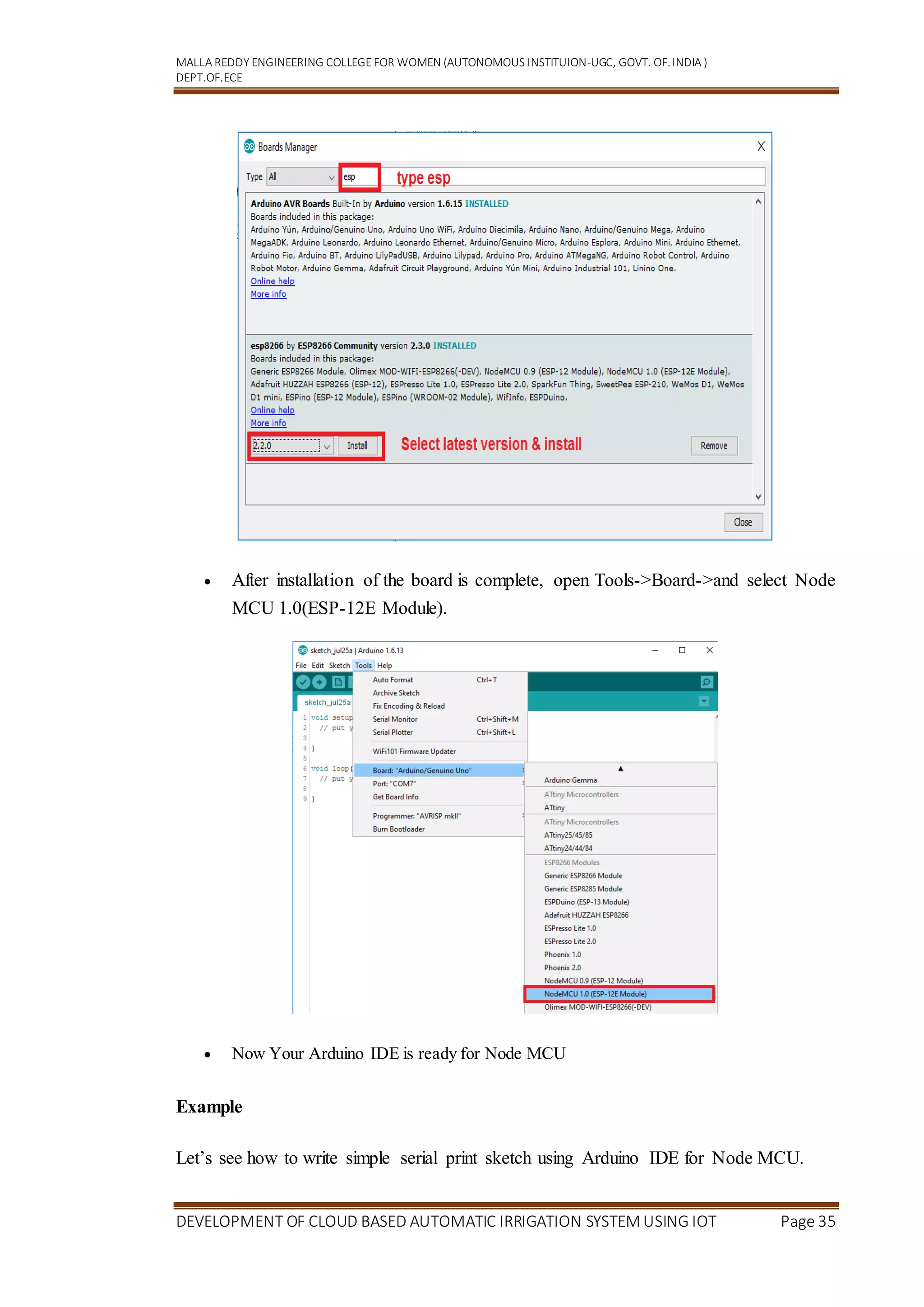
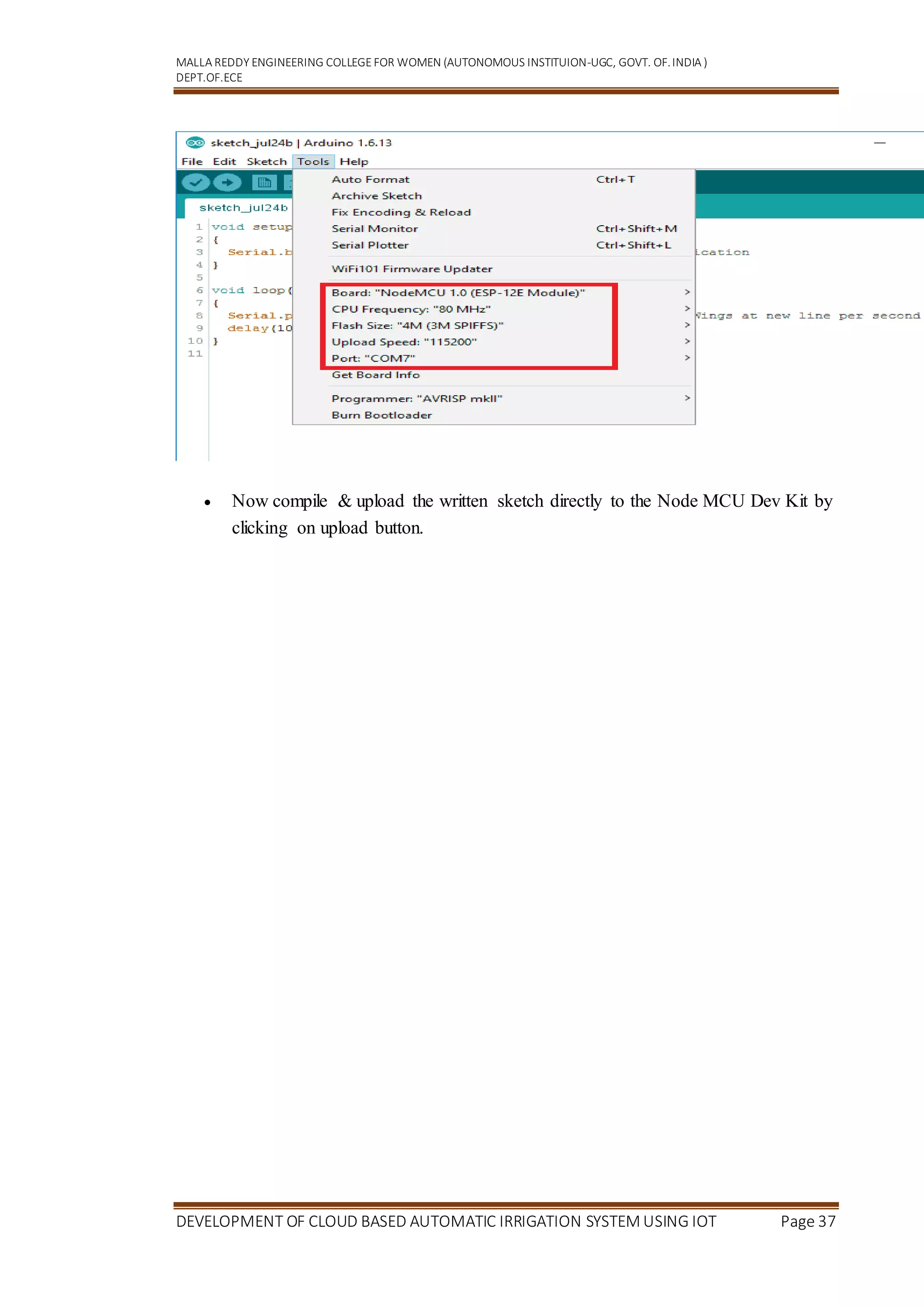
Getting Started with Node MCU using Arduino IDE
5.1 Introduction
Node MCU is Lua based firmware of ESP8266. Generally, ESPlorer IDE is referred for
writing Lua scripts for Node MCU. It requires to get familiar with ESPlorer IDE and
Lua scripting language. There is another way of developing Node MCU with a well-
known IDE . First download Arduino IDE(version1.6+) .
https://www.arduino.cc/en/Main/Software
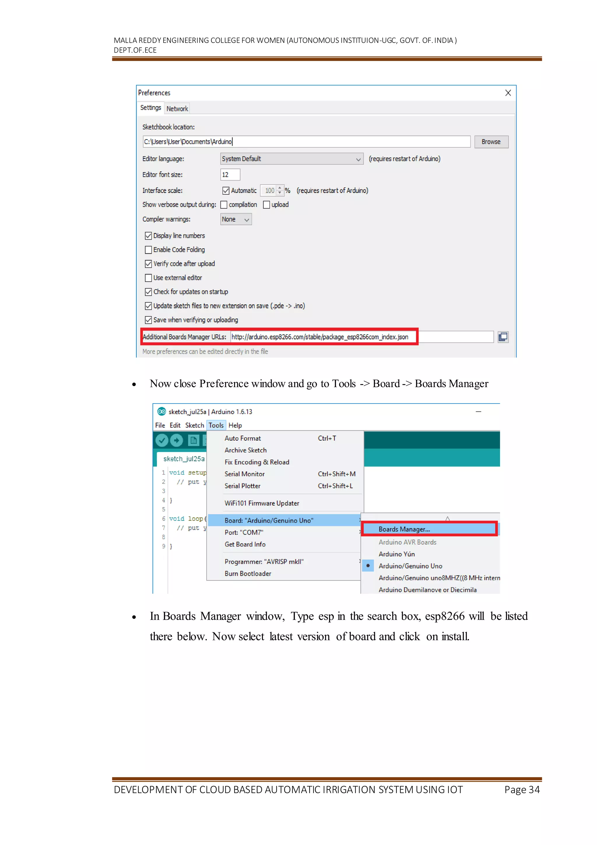
Open Arduino IDE and Go to File -> Preference.
Now on Preference window, Enter below link in Additional Boards Manager
URLs[ http://arduino.esp8266.com/stable/package_esp8266com_index.json]
34. MALLA REDDY ENGINEERING COLLEGEFOR WOMEN (AUTONOMOUS INSTITUION-UGC, GOVT. OF.INDIA )
DEPT.OF.ECE
DEVELOPMENT OF CLOUD BASED AUTOMATIC IRRIGATION SYSTEM USING IOT Page 34
Now close Preference window and go to Tools -> Board -> Boards Manager
In Boards Manager window, Type esp in the search box, esp8266 will be listed
there below. Now select latest version of board and click on install.
35. MALLA REDDY ENGINEERING COLLEGEFOR WOMEN (AUTONOMOUS INSTITUION-UGC, GOVT. OF.INDIA )
DEPT.OF.ECE
DEVELOPMENT OF CLOUD BASED AUTOMATIC IRRIGATION SYSTEM USING IOT Page 35
After installation of the board is complete, open Tools->Board->and select Node
MCU 1.0(ESP-12E Module).
Now Your Arduino IDE is ready for Node MCU
Example
Let’s see how to write simple serial print sketch using Arduino IDE for Node MCU.
36. MALLA REDDY ENGINEERING COLLEGEFOR WOMEN (AUTONOMOUS INSTITUION-UGC, GOVT. OF.INDIA )
DEPT.OF.ECE
DEVELOPMENT OF CLOUD BASED AUTOMATIC IRRIGATION SYSTEM USING IOT Page 36
First connect Node MCU Development Kit with PC as shown in below figure.
Fig. Node MCU connection with PC
After setting up Arduino IDE for Node MCU, open Arduino IDE and write
simple sketch of serial print as shown in below figure.
Arduino Sketch
void setup()
{
Serial.begin(9600); /* initialise serial communication */
}
void loop()
{
Serial.println("EdugeneTechnologies"); /* print Electronic Wings at new line per second */
delay(1000);
}
37. MALLA REDDY ENGINEERING COLLEGEFOR WOMEN (AUTONOMOUS INSTITUION-UGC, GOVT. OF.INDIA )
DEPT.OF.ECE
DEVELOPMENT OF CLOUD BASED AUTOMATIC IRRIGATION SYSTEM USING IOT Page 37
Now compile & upload the written sketch directly to the Node MCU Dev Kit by
clicking on upload button.