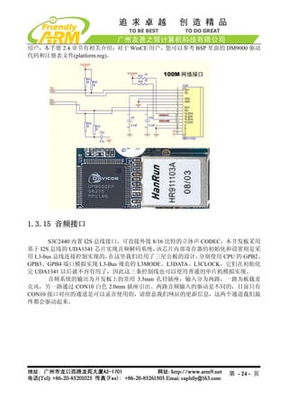
CON1,CON2,CON3 在开发板上的位置和原理图中的连接定义对应关系如下图所示。
1.3.11 USB接口
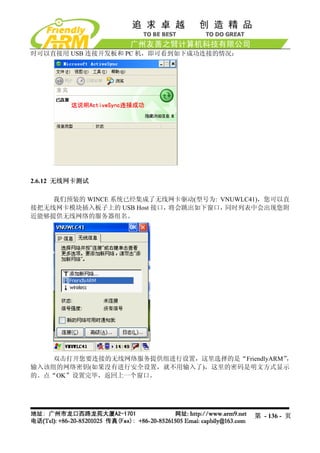
本开发板具有两种 USB 接口, 一个是 USB Host,它和普通 PC 的 USB 接口是一样的,
可以接 USB 摄像头、 USB 键盘、USB 鼠标、优盘等常见的 USB 外设, 另外一种是 USB Slave,
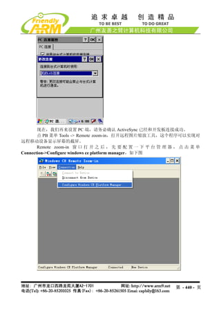
我们一般使用它来下载程序到目标板, 当开发板装载了 WinCE 系统时, 它可以通过 ActiveSync
软件和 Windows 系统进行同步, 当开发板装载了 Linux 系统时, 目前尚无相应的驱动和应用。
为了方便用户通过程序控制 USB Slave 和 PC 的通断,我们设置了 USB_EN 信号,如图,它
使用的 CPU 资源为 GPC5。
我们将提更加广泛的 USB Host 外设应用,请经常留意我们网站的更新信息。
第 - 21 - 页
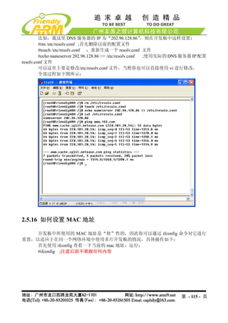
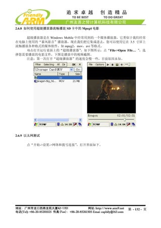
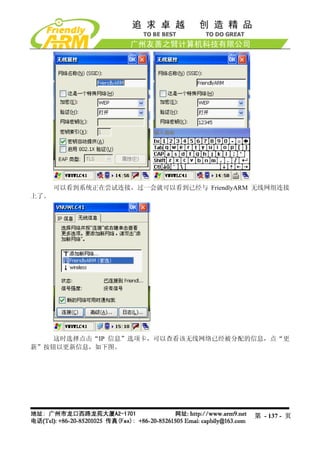
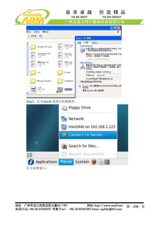
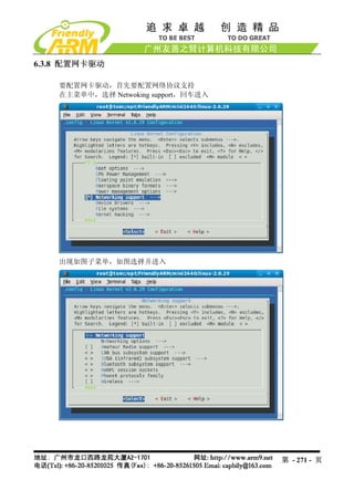
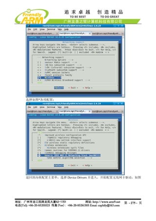
2.5.21 使用 USB无线网卡
Linux-2.6.29 内核已经自带了部分 USB 无线网卡的驱动,其中包括目前最流行、性价
比最高的 TP-Link USB WiFi 无线网卡:TL-WN321G+,本开发板的缺省内核映象已经加入了
本模块的支持。
提示:本手册的 6.3 章节有关于在内核中配置无线网卡驱动的说明
把 USB 无线网卡插入开发板,会出现如下信息:
[root@FriendlyARM /]# usb 1-1: new full speed USB device using s3c2410-ohci and
address 2
usb 1-1: New USB device found, idVendor=148f, idProduct=2573
usb 1-1: New USB device strings: Mfr=1, Product=2, SerialNumber=0
usb 1-1: Product: 54M.USB.......
usb 1-1: Manufacturer: Ralink
usb 1-1: configuration #1 chosen from 1 choice
wmaster0 (rt73usb): not using net_device_ops yet
wlan0 (rt73usb): not using net_device_ops yet
[root@FriendlyARM /]#
第 - 120 - 页
121.
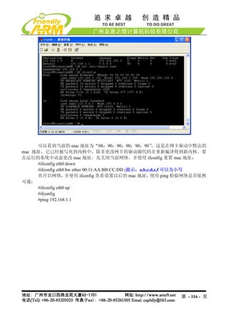
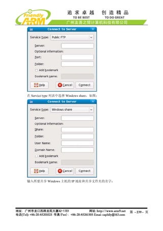
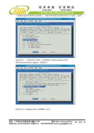
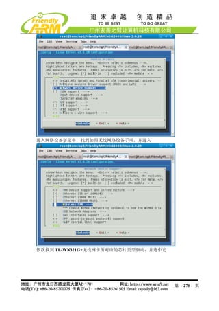
这说明已经识别到该无线网卡,然后通过步骤命令开始配置。
(1)首先关闭开发板的有线网卡 DM9000
[root@FriendlyARM /]#ifconfig eth0 down
(2)加载 USB WiFi 无线网卡
[root@FriendlyARM /]# ifconfig wlan0 up
rt73usb 1-1:1.0: firmware: requesting rt73.bin
[root@FriendlyARM /]#
(3)扫描可用的无线网络
[root@FriendlyARM /]# iwlist scanning | grep ESSID
lo Interface doesn't support scanning.
eth0 Interface doesn't support scanning.
wmaster0 Interface doesn't support scanning.
ESSID:"FRIENDLY-ARM"
ESSID:"NETGEAR"
ESSID:"TP-LINK"
[root@FriendlyARM /]#
(4)选择要连接的无线网络
[root@FriendlyARM /]# iwconfig wlan0 essid "FRIENDLY-ARM"
(5)输入该网络的安全密码
[root@FriendlyARM /]# iwconfig wlan0 key s:12345
(6)连接到指定的 AP(无线路由)
[root@FriendlyARM /]# iwconfig wlan0 ap auto
(7)设置无线网卡的 IP 地址
[root@FriendlyARM /]# ifconfig wlan0 192.168.1.120
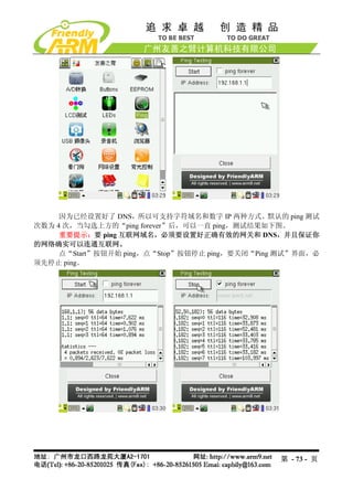
(8)使用 ping 命令检测无线网连通状况
[root@FriendlyARM /]# ping 192.168.1.1
PING 192.168.1.1 (192.168.1.1): 56 data bytes
64 bytes from 192.168.1.1: seq=0 ttl=64 time=42.804 ms
64 bytes from 192.168.1.1: seq=1 ttl=64 time=5.020 ms
64 bytes from 192.168.1.1: seq=2 ttl=64 time=5.021 ms
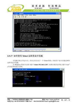
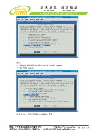
以上整个过程如下所示:
[root@FriendlyARM /]# usb 1-1: new full speed USB device using s3c2410-ohci and
address 2
usb 1-1: New USB device found, idVendor=148f, idProduct=2573
usb 1-1: New USB device strings: Mfr=1, Product=2, SerialNumber=0
usb 1-1: Product: 54M.USB.......
usb 1-1: Manufacturer: Ralink
usb 1-1: configuration #1 chosen from 1 choice
第 - 121 - 页
122.
wmaster0 (rt73usb): notusing net_device_ops yet
wlan0 (rt73usb): not using net_device_ops yet
[root@FriendlyARM /]# ifconfig eth0 down
[root@FriendlyARM /]# ifconfig wlan0 up
rt73usb 1-1:1.0: firmware: requesting rt73.bin
[root@FriendlyARM /]# iwconfig wlan0 key s:12345
[root@FriendlyARM /]# iwconfig wlan0 essid "FRIENDLY-ARM"
[root@FriendlyARM /]# iwconfig wlan0 ap auto
[root@FriendlyARM /]# ifconfig wlan0 192.168.1.120
[root@FriendlyARM /]# ping 192.168.1.1
PING 192.168.1.1 (192.168.1.1): 56 data bytes
64 bytes from 192.168.1.1: seq=0 ttl=64 time=42.804 ms
64 bytes from 192.168.1.1: seq=1 ttl=64 time=5.020 ms
64 bytes from 192.168.1.1: seq=2 ttl=64 time=5.021 ms
^C
--- 192.168.1.1 ping statistics ---
3 packets transmitted, 3 packets received, 0% packet loss
round-trip min/avg/max = 5.020/17.615/42.804 ms
[root@FriendlyARM /]#
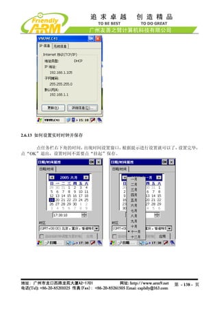
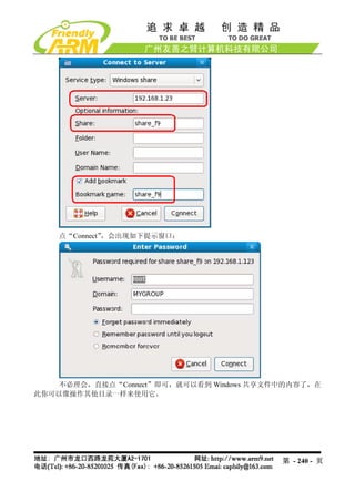
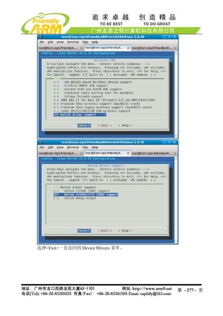
2.5.22 设置并保存系统实时时钟
Linux 中更改时间的方法一般使用 date 命令,为了把 S3C2440 内部带的时钟与 linux 系统时钟同
步,一般使用 hwclock 命令,下面是它们的使用方法:
(1) date -s 042916352007 #设置时间为 2007-04-29 16:34
(2) hwclock -w #把刚刚设置的时间存入 S3C2440 内部的 RTC
(3).开机时使用 hwclock -s 命令可以恢复 linux 系统时钟为 RTC, 一般把该语句放入
/etc/init.d/rcS 文件自动执行。
注意:我们提供的系统已经把 hwclock –s 命令写入 rcS 文件。
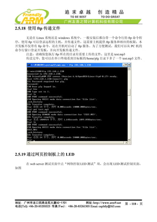
2.5.23 如何掉电保存数据到 Flash
由于本系统采用了可读写文件系统 yaffs(在嵌入式系统中,专门管理 Flash 存储器的
一种文件系统),因此可以很方便的动态保存数据,掉电后不会丢失。开机后在串口终端运行
以下命令:
#cp / shanghaitan.mp3 /home/plg
此时将在/home/fa 目录下复制一个同样的文件,然后关机,重新开启系统,可以查看
到/home/plg 目录下的文件依然存在。
第 - 122 - 页
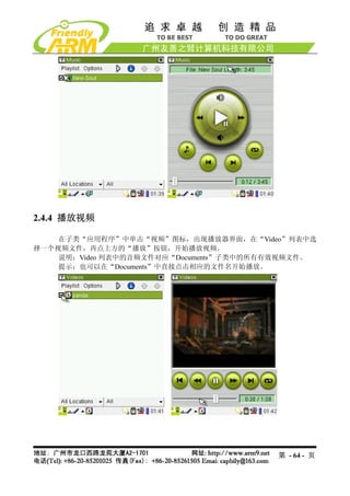
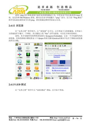
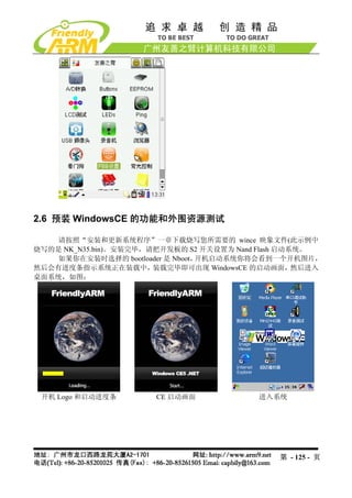
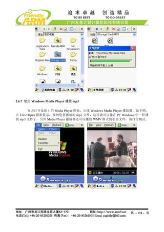
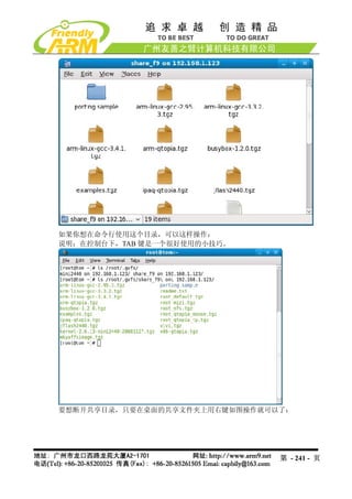
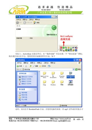
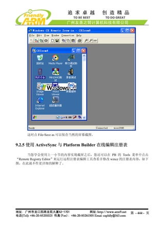
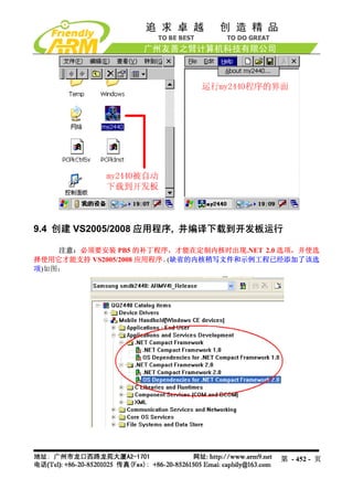
2.6.7 使用 WindowsMedia Player 播放 mp3
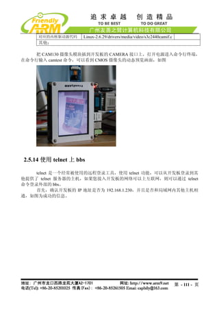
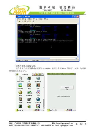
双击打开桌面上的 Media Player 图标,出现 Windows Media Player 播放器,如下图,
点 File->Open 根据提示,找到您要播放的 mp3 文件,这样就可以像在 PC Windows 中一样播
放 mp3 文件了,另外 Media Player 播放器还可以播放 WMV 格式的影音文件,请自行测试。
第 - 131 - 页
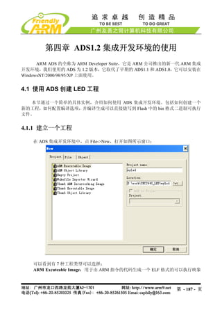
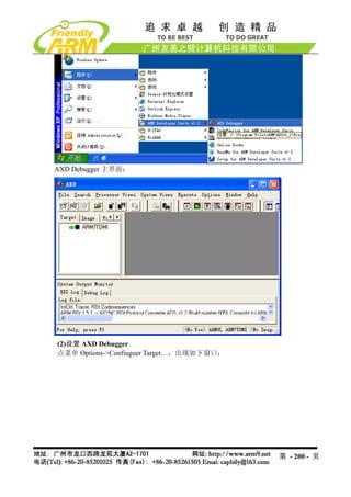
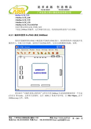
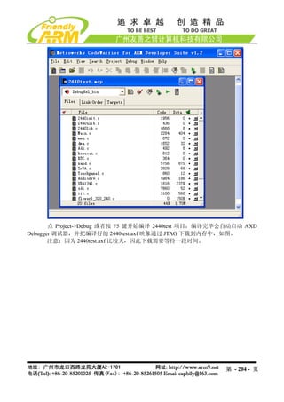
第四章 ADS1.2 集成开发环境的使用
ARM ADS 的全称为 ARM Developer Suite,它是 ARM 公司推出的新一代 ARM 集成
开发环境,我们使用的 ADS 为 1.2 版本,它取代了早期的 ADS1.1 和 ADS1.0,它可以安装在
WindowsNT/2000/98/95/XP 上面使用。
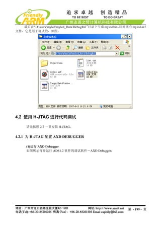
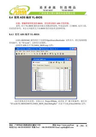
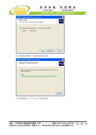
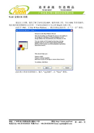
4.1 使用 ADS 创建 LED 工程
本节通过一个简单的具体实例,介绍如何使用 ADS 集成开发环境。包括如何创建一个
新的工程,如何配置编译选项,并编译生成可以直接烧写到 Flash 中的 bin 格式二进制可执行
文件。
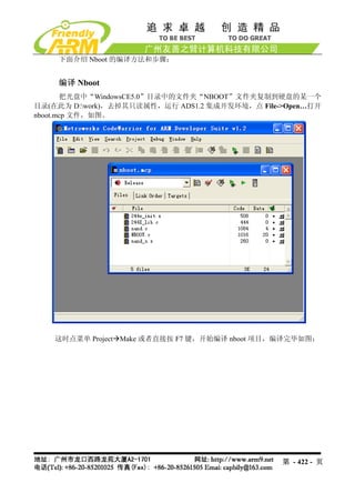
4.1.1 建立一个工程
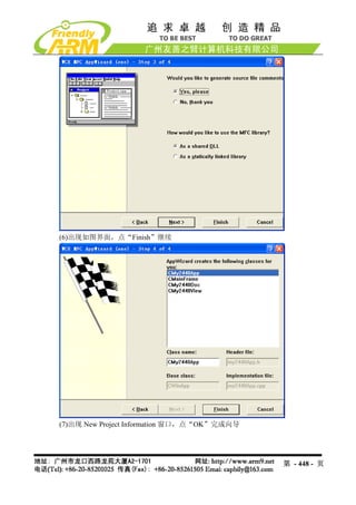
在 ADS 集成开发环境中,点 File->New,打开如图所示窗口:
可以看到有 7 种工程类型可以选择:
ARM Excuteable Image:用于由 ARM 指令的代码生成一个 ELF 格式的可以执行映象
第 - 187 - 页
188.
文件。
ARM Object Library:用于由 ARM 指令的代码生成一个 armar 格式的目标文件库。
Empty Project:用于创建一个不包含任何库或者源文件的工程。
Makefile Importer Wizard:用于将 Visual C 的 nmake 或者 GNU make 文件转入到
CodeWarrior IDE 工程文件。
Thumb ARM Excutable Image:用于由 ARM 指令和 Thumb 指令的混和代码生成一个
可执行的 ELF 格式的映象文件。
Thumb Excutable image: 用于由 Thumb 指令创建一个可执行的 ELF 格式的映象文件。
Thumb Object Library:用于由 Thumb 指令的代码生成一个 armar 格式的目标文件库。
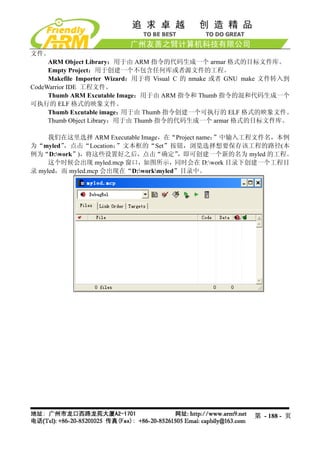
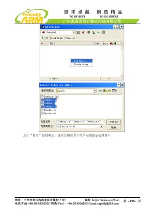
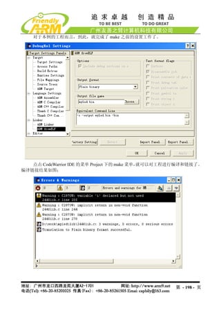
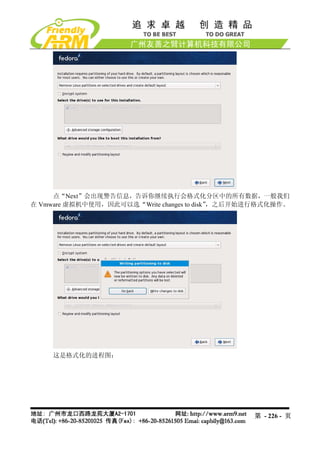
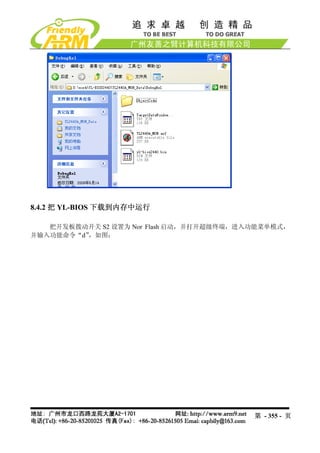
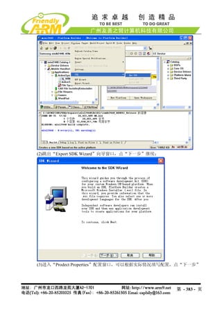
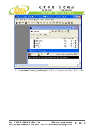
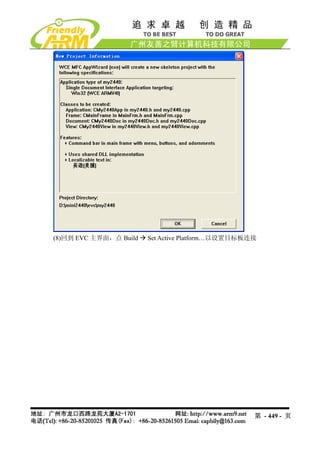
我们在这里选择 ARM Executable Image,在“Project name:”中输入工程文件名,本例
为“myled”,点击“Location: ”文本框的“Set”按钮,浏览选择想要保存该工程的路径(本
例为“D:work”),将这些设置好之后,点击“确定” ,即可创建一个新的名为 myled 的工程。
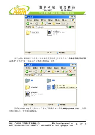
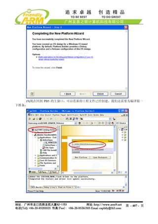
这个时候会出现 myled.mcp 窗口,如图所示,同时会在 D:work 目录下创建一个工程目
录 myled,而 myled.mcp 会出现在“D:workmyled”目录中。
第 - 188 - 页
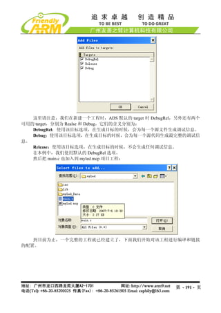
这里的设置有很多,我们主要介绍最常用的一些选项。
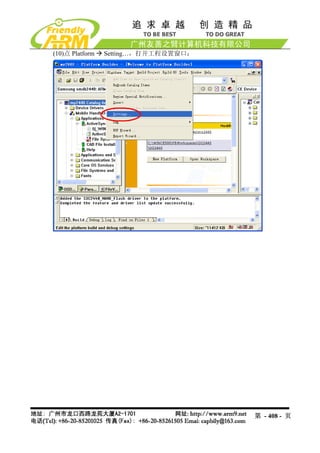
Target Setting
Target Name 文本框显示了当前的目标设置。
Linker 选项为用户提供了要使用的连链接器,在这里选择默认的 ARM Linker,使用该
链接器,将使用 armlink 链接编译器和汇编器生成相应的工程目标文件。
在 Linker 设置中,还有两个可选项,None 代表不对生成的各个源代码目标文件进行链
接,ARM Librarian 表示将编译或者汇编得到的目标文件转换为 ARM 库文件,对于本例,使
用默认的链接器 ARM Linker。
Pre-Linker:目前 ADS 并不支持该选项。
Post-Linker:选择在链接完成后,还要对输出文件进行的操作。因为在本例中,希望生
成一个可以烧写到 Flash 中去的二进制代码,所以在此选择 ARM fromELF,表示在链接生成
映象文件后, 再调用 fromELF 命令将含有调试信息的 ELF 格式的映象文件转换为其他格式的
文件。
Target Setting 选择最后设置如图所示:
第 - 193 - 页
194.
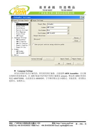
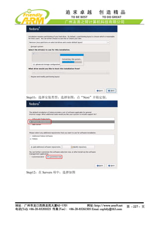
Language Settings
因为在本例中包含汇编代码,所有要用到汇编器,点接选择 ARM Assembler,在右侧
出现相应的设置选项,在 ADS 集成开发环境中用的汇编器是 armasm,默认的 ARM 体系结
构是 ARM7TDMI,在此要改为 ARM920T,字节顺序默认是小端模式,其他设置,采用默认
值即可,如图所示:
第 - 194 - 页
195.
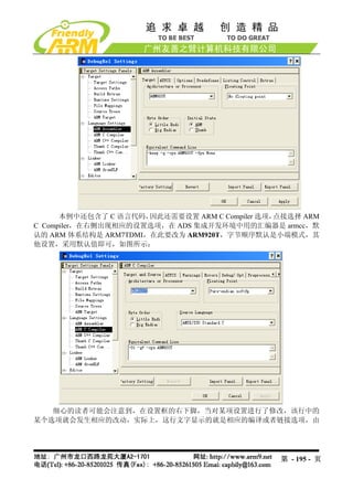
本例中还包含了 C 语言代码,因此还需要设置 ARM C Compiler 选项,点接选择 ARM
C Compiler,在右侧出现相应的设置选项,在 ADS 集成开发环境中用的汇编器是 armcc,默
认的 ARM 体系结构是 ARM7TDMI,在此要改为 ARM920T,字节顺序默认是小端模式,其
他设置,采用默认值即可,如图所示:
细心的读者可能会注意到,在设置框的右下脚,当对某项设置进行了修改,该行中的
某个选项就会发生相应的改动,实际上,这行文字显示的就是相应的编译或者链接选项,由
第 - 195 - 页
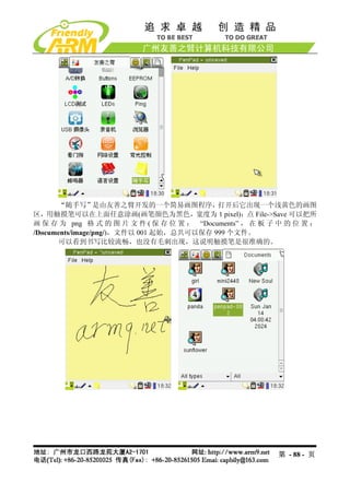
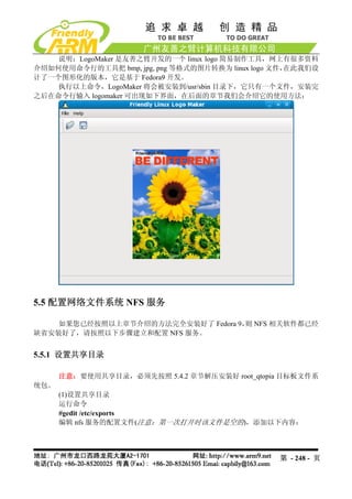
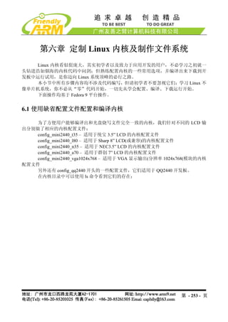
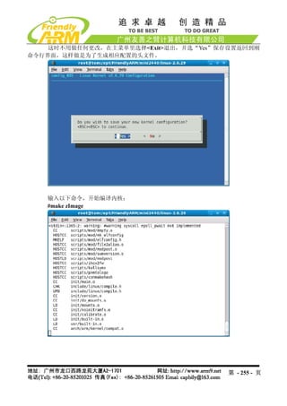
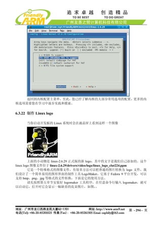
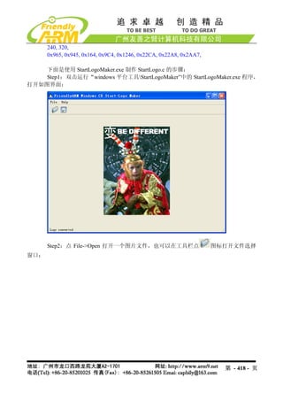
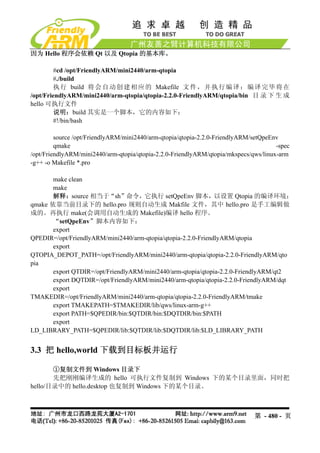
图片会显示在 logomaker 窗口中,如图
这时点 File->Convert the picture to a Linux Logo File,或者使用快捷键 Crtl+C 会跳出
文件保存目录窗口,不需要输入任何东西,选择要保存的目录即可,文件名将会自动保存为
linux_logo_clut224.ppm,使用这个文件代替 linux-2.6.29/drivers/video/logo 目录下的同名文件
即可。
第 - 296 - 页
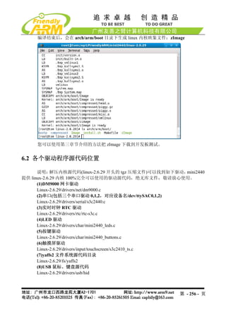
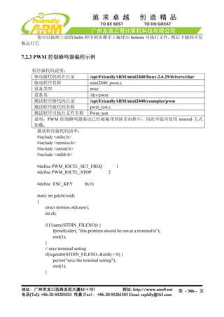
static void set_buzzer_freq(intfreq)
{
// this IOCTL command is the key to set frequency
int ret = ioctl(fd, PWM_IOCTL_SET_FREQ, freq);
if(ret < 0) {
perror("set the frequency of the buzzer");
exit(1);
}
}
static void stop_buzzer(void)
{
int ret = ioctl(fd, PWM_IOCTL_STOP);
if(ret < 0) {
perror("stop the buzzer");
exit(1);
}
}
int main(int argc, char **argv)
{
int freq = 1000 ;
open_buzzer();
printf( "nBUZZER TEST ( PWM Control )n" );
printf( "Press +/- to increase/reduce the frequency of the BUZZERn" ) ;
printf( "Press 'ESC' key to Exit this programnn" );
while( 1 )
{
int key;
set_buzzer_freq(freq);
printf( "tFreq = %dn", freq );
key = getch();
switch(key) {
case '+':
第 - 308 - 页
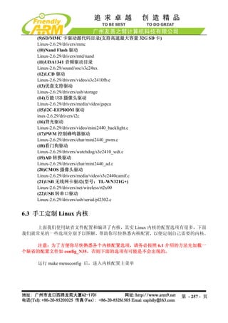
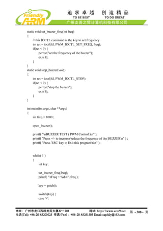
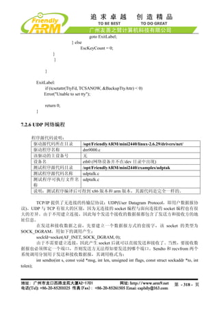
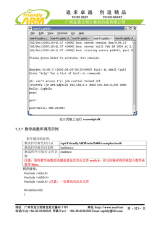
在嵌入式 Linux 系统中,大部分的硬件都需要类似的驱动才能操作,比如触摸屏、网卡、音
频等,在这里我们介绍的是一些简单典型的例子,实际上复杂的驱动都有参考代码,不必从
头写驱动。
在本节中,我们不介绍驱动程序理论概念之类的内容,那些在网上或者书籍中都有比
较系统的描述。
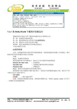
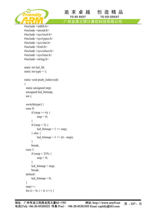
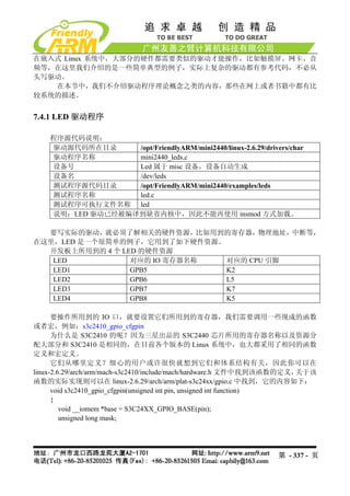
7.4.1 LED 驱动程序
程序源代码说明:
驱动源代码所在目录 /opt/FriendlyARM/mini2440/linux-2.6.29/drivers/char
驱动程序名称 mini2440_leds.c
设备号 Led 属于 misc 设备,设备自动生成
设备名 /dev/leds
测试程序源代码目录 /opt/FriendlyARM/mini2440/examples/leds
测试程序名称 led.c
测试程序可执行文件名称 led
说明:LED 驱动已经被编译到缺省内核中,因此不能再使用 insmod 方式加载。
要写实际的驱动,就必须了解相关的硬件资源,比如用到的寄存器,物理地址,中断等,
在这里,LED 是一个很简单的例子,它用到了如下硬件资源。
开发板上所用到的 4 个 LED 的硬件资源
LED 对应的 IO 寄存器名称 对应的 CPU 引脚
LED1 GPB5 K2
LED2 GPB6 L5
LED3 GPB7 K7
LED4 GPB8 K5
要操作所用到的 IO 口,就要设置它们所用到的寄存器,我们需要调用一些现成的函数
或者宏,例如:s3c2410_gpio_cfgpin
为什么是 S3C2410 的呢?因为三星出品的 S3C2440 芯片所用的寄存器名称以及资源分
配大部分和 S3C2410 是相同的,在目前各个版本的 Linux 系统中,也大都采用了相同的函数
定义和宏定义。
它们从哪里定义?细心的用户或许很快就想到它们和体系结构有关,因此你可以在
linux-2.6.29/arch/arm/mach-s3c2410/include/mach/hardware.h 文件中找到该函数的定义, 关于该
函数的实际实现则可以在 linux-2.6.29/arch/arm/plat-s3c24xx/gpio.c 中找到,它的内容如下:
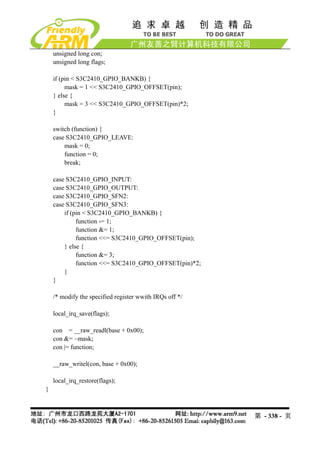
void s3c2410_gpio_cfgpin(unsigned int pin, unsigned int function)
{
void __iomem *base = S3C24XX_GPIO_BASE(pin);
unsigned long mask;
第 - 337 - 页
338.
unsigned long con;
unsigned long flags;
if (pin < S3C2410_GPIO_BANKB) {
mask = 1 << S3C2410_GPIO_OFFSET(pin);
} else {
mask = 3 << S3C2410_GPIO_OFFSET(pin)*2;
}
switch (function) {
case S3C2410_GPIO_LEAVE:
mask = 0;
function = 0;
break;
case S3C2410_GPIO_INPUT:
case S3C2410_GPIO_OUTPUT:
case S3C2410_GPIO_SFN2:
case S3C2410_GPIO_SFN3:
if (pin < S3C2410_GPIO_BANKB) {
function -= 1;
function &= 1;
function <<= S3C2410_GPIO_OFFSET(pin);
} else {
function &= 3;
function <<= S3C2410_GPIO_OFFSET(pin)*2;
}
}
/* modify the specified register wwith IRQs off */
local_irq_save(flags);
con = __raw_readl(base + 0x00);
con &= ~mask;
con |= function;
__raw_writel(con, base + 0x00);
local_irq_restore(flags);
}
第 - 338 - 页
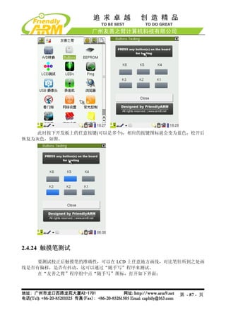
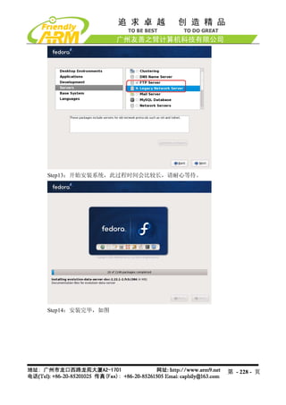
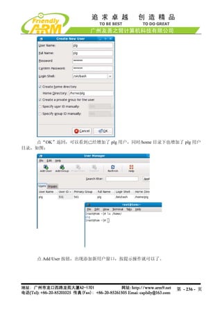
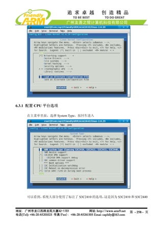
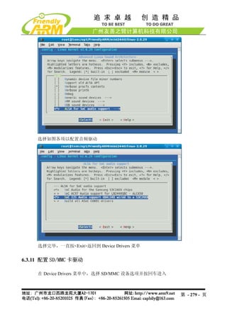
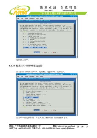
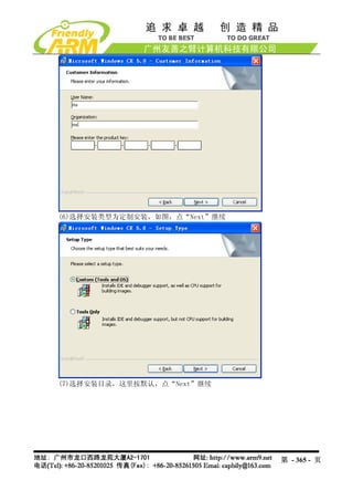
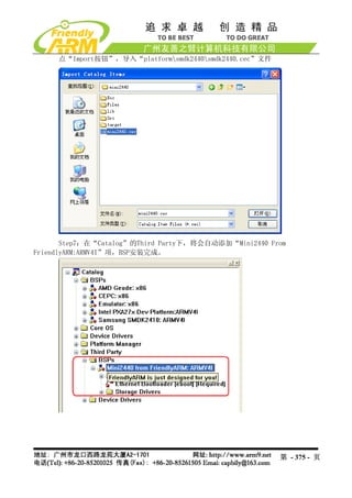
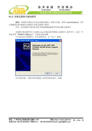
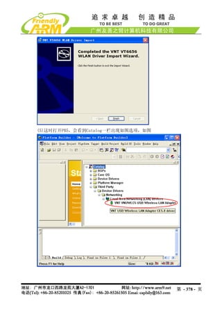
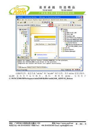
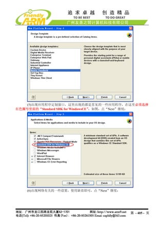
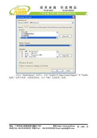
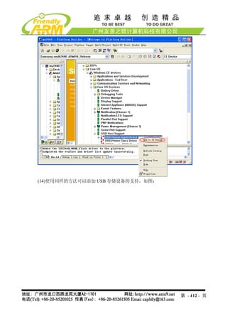
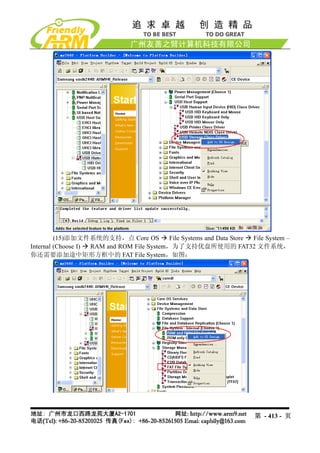
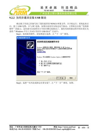
(13)加入 USB 鼠标和键盘的支持,在Catalog 一栏依次点击展开 Core OS Windows
CE device Core OS Services USB Host Support USB Human Input Device(HID) Class
Driver,点右键选择 “Add to OS Design”,并展开其子项添加 “USB HID Keyboard and Mouse” ,
如图:
第 - 411 - 页
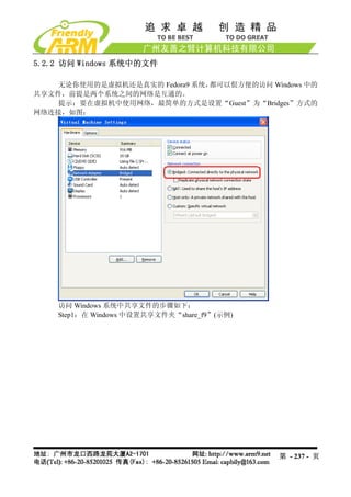
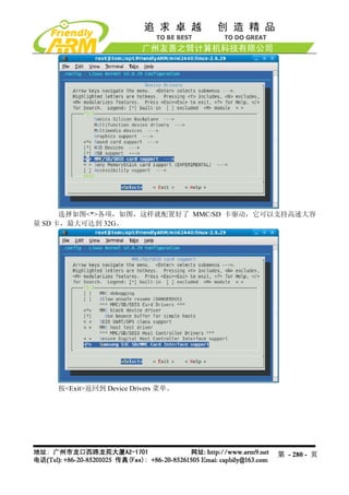
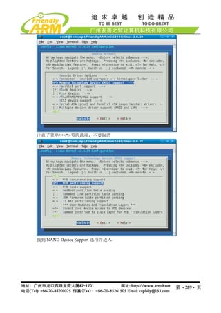
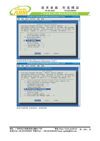
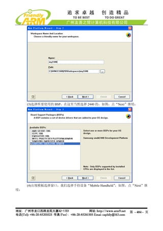
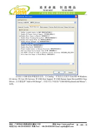
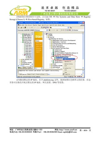
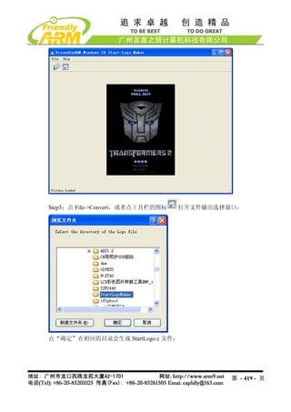
(15)添加文件系统的支持,点 Core OS File Systems and Data Store File System –
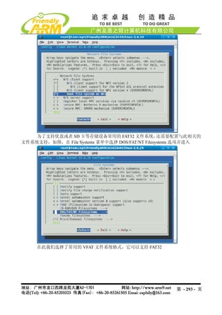
Internal (Choose I) RAM and ROM File System,为了支持优盘所使用的 FAT32 文件系统,
你还需要添加途中矩形方框中的 FAT File System,如图:
第 - 413 - 页
414.
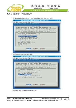
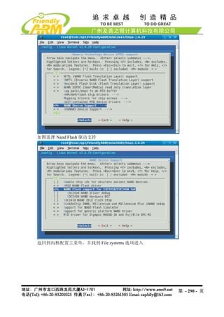
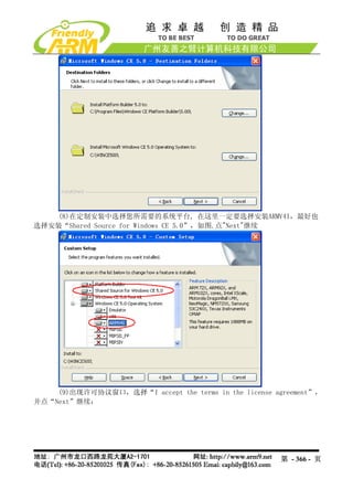
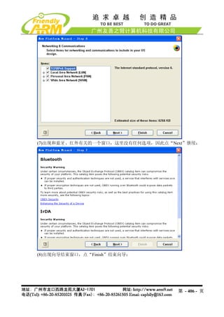
(16)添加注册表保存卡支持,点 Core OS File Systems and Data Store Registry
Storage (Choose I) Hive-based Registry, 如图:
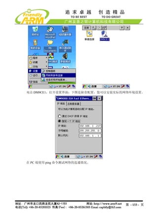
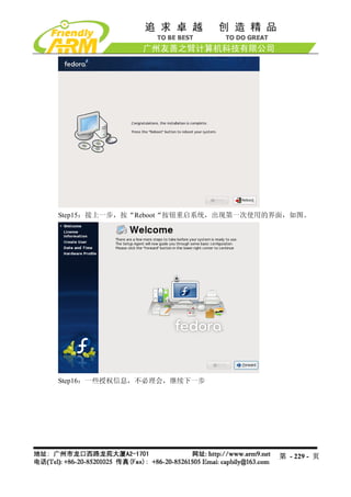
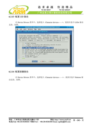
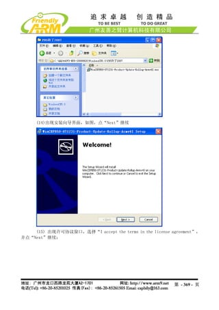
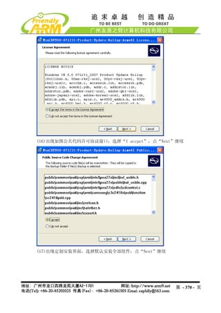
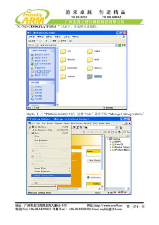
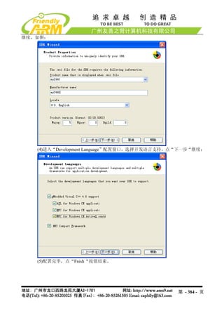
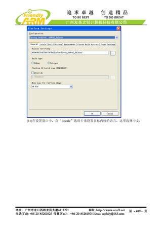
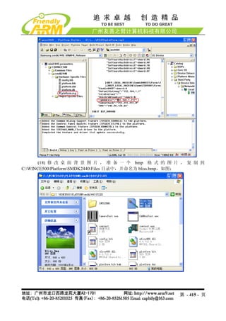
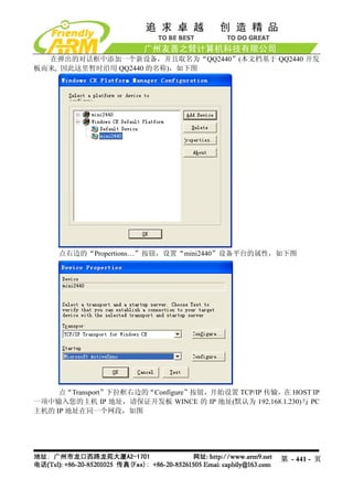
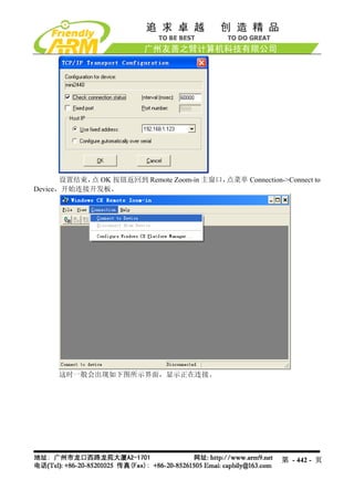
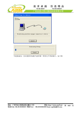
(17)修改默认的 IP 地址,打开 platform.reg 文件,找到如图红色框所示的位置,在这
里你可以修改开机后默认的 IP 地址,网关设置,DNS 等设置:
第 - 414 - 页
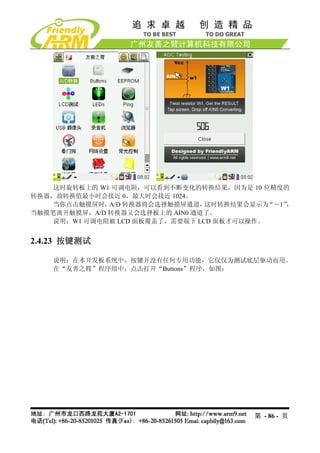
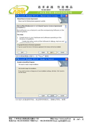
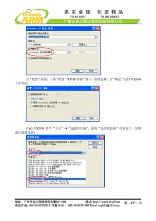
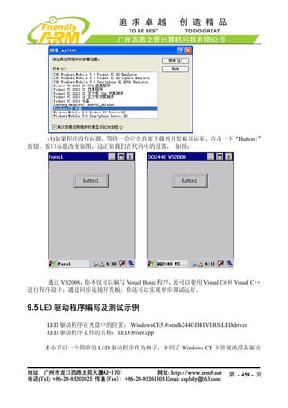
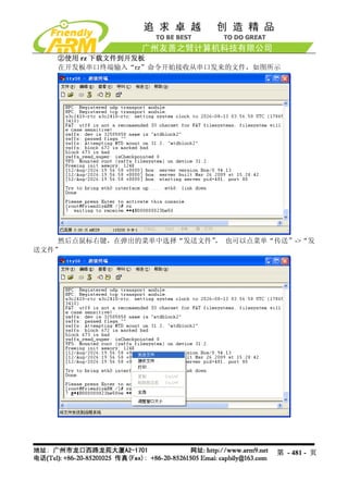
(3)如果程序没有问题,等待一会它会直接下载到开发板并运行,点击一下“Button1”
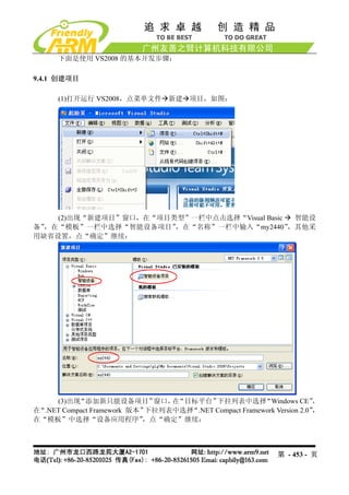
按钮,窗口标题改变如图,这正如我们在代码中的设置, 如图:
通过 VS2008,你不仅可以编写 Visual Basic 程序,还可以使用 Visual C#和 Visual C++
进行程序设计,通过同步连接开发板,你还可以实现单步调试运行。
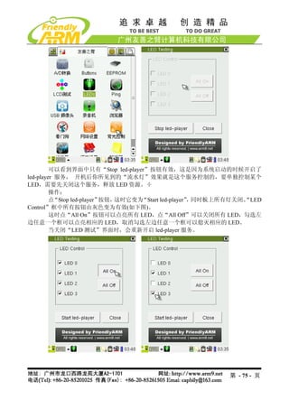
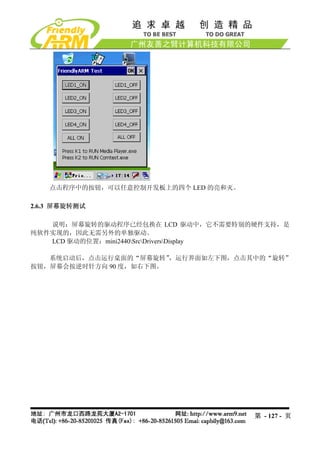
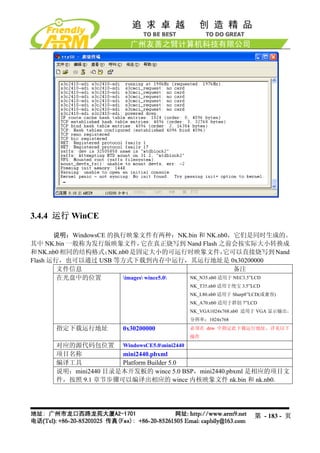
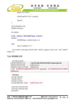
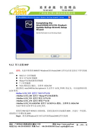
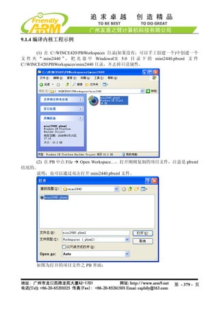
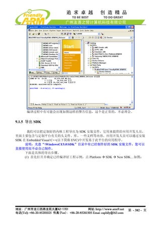
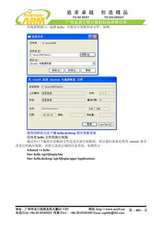
9.5 LED 驱动程序编写及测试示例
LED 驱动程序在光盘中的位置:WindowsCE5.0smdk2440DRIVERSLEDdriver
LED 驱动程序文件的名称:LEDDriver.cpp
本小节以一个简单的 LED 驱动程序作为例子,介绍了 Windows CE 下常规流设备驱动
第 - 459 - 页
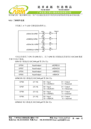
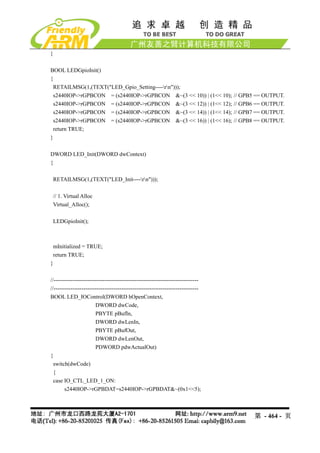
因此,要使用 GPB5~8,需要:
(1) 设置 GPBCON,以使引脚功能为 IO 功能输出
(2) 要点亮 LED, GPBDAT 对应的位要设置为 0
(3) 要熄灭 LED, GPBDAT 对应的位要设置为 1
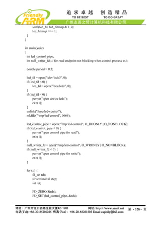
9.5.2 编写 LED 流式驱动程序
流式驱动是 WinCE 驱动程序的一种常规方式,应用程序通过文件系统,透过
DeviceManager 以访问文件的形式访问驱动程序,调用 IOCTL 向驱动程序下达指令。所有的
流式驱动程序都需实现一组统一的接口。
流式驱动框架:
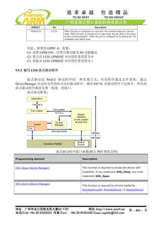
流式驱动程序接口函数(摘自 PB5 帮助文档)
Programming element Description
XXX_Close (Device Manager) This function is required to access the device with
CreateFile. If you implement XXX_Close, you must
implement XXX_Open.
XXX_Deinit (Device Manager)
This function is required by drivers loaded by
ActivateDeviceEx, ActivateDevice, or RegisterDevice.
第 - 461 - 页
462.
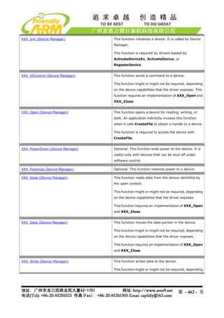
XXX_Init (Device Manager) This function initializes a device. It is called by Device
Manager.
This function is required by drivers loaded by
ActivateDeviceEx, ActivateDevice, or
RegisterDevice.
XXX_IOControl (Device Manager) This function sends a command to a device.
This function might or might not be required, depending
on the device capabilities that the driver exposes. This
function requires an implementation of XXX_Open and
XXX_Close.
XXX_Open (Device Manager) This function opens a device for reading, writing, or
both. An application indirectly invokes this function
when it calls CreateFile to obtain a handle to a device.
This function is required to access the device with
CreateFile.
XXX_PowerDown (Device Manager) Optional. This function ends power to the device. It is
useful only with devices that can be shut off under
software control.
XXX_PowerUp (Device Manager) Optional. This function restores power to a device.
XXX_Read (Device Manager) This function reads data from the device identified by
the open context.
This function might or might not be required, depending
on the device capabilities that the driver exposes.
This function requires an implementation of XXX_Open
and XXX_Close.
XXX_Seek (Device Manager) This function moves the data pointer in the device.
This function might or might not be required, depending
on the device capabilities that the driver exposes.
This function requires an implementation of XXX_Open
and XXX_Close.
XXX_Write (Device Manager) This function writes data to the device.
This function might or might not be required, depending
第 - 462 - 页
463.
on the devicecapabilities that the driver exposes.
This function requires an implementation of XXX_Open
and XXX_Close.
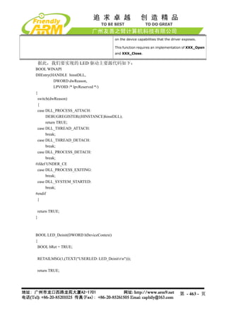
据此,我们要实现的 LED 驱动主要源代码如下:
BOOL WINAPI
DllEntry(HANDLE hinstDLL,
DWORD dwReason,
LPVOID /* lpvReserved */)
{
switch(dwReason)
{
case DLL_PROCESS_ATTACH:
DEBUGREGISTER((HINSTANCE)hinstDLL);
return TRUE;
case DLL_THREAD_ATTACH:
break;
case DLL_THREAD_DETACH:
break;
case DLL_PROCESS_DETACH:
break;
#ifdef UNDER_CE
case DLL_PROCESS_EXITING:
break;
case DLL_SYSTEM_STARTED:
break;
#endif
}
return TRUE;
}
BOOL LED_Deinit(DWORD hDeviceContext)
{
BOOL bRet = TRUE;
RETAILMSG(1,(TEXT("USERLED: LED_Deinitrn")));
return TRUE;
第 - 463 - 页
RETAILMSG(1,(TEXT("USERLED: LED_Seekrn")));
return 0;
}
//-----------------------------------------------------------------------------
//-----------------------------------------------------------------------------
DWORD LED_Write(DWORD hOpenContext, LPCVOID pSourceBytes, DWORD NumberOfBytes)
{
RETAILMSG(1,(TEXT("USERLED: LED_Writern")));
return 0;
}
DWORD LED_Seek(DWORD hOpenContext, long Amount, DWORD Type)
{
RETAILMSG(1,(TEXT("USERLED: LED_Seekrn")));
return 0;
}
//-----------------------------------------------------------------------------
//-----------------------------------------------------------------------------
DWORD LED_Write(DWORD hOpenContext, LPCVOID pSourceBytes, DWORD NumberOfBytes)
{
RETAILMSG(1,(TEXT("USERLED: LED_Writern")));
return 0;
}
9.5.3 把 LED 驱动程序添加到 BSP 中以编译
LED 驱动程序必须要编译到内核中才能使用,要把 LED 驱动程序编译到内核中,需
要做如下步骤:
(1) 在 smdk2440DRIVERS 下建立 LEDdriver 目录,并在 dirs 文件中加入此目录,使
系统编译 bsp 的时候可以编译这个文件
(2)在 smdk2440DRIVERSLEDriver目录中建立 makefile 文件,内容如下:
#
# DO NOT EDIT THIS FILE!!! Edit .sources. if you want to add a new source
# file to this component. This file merely indirects to the real make file
# that is shared by all the components of Peg
#
!INCLUDE $(_MAKEENVROOT)makefile.def
第 - 467 - 页
468.
(3)在 smdk2440DRIVERSLEDriver目录中建立 source文件,内容如下:
!if 0
File: sources
Author: jeffmi
Copyright (c) 1995-2002 Microsoft Corporation. All rights reserved.
!endif
RELEASETYPE=PLATFORM
TARGETNAME=LEDDriver
TARGETTYPE=DYNLINK
DLLENTRY=DllEntry
TARGETLIBS=
$(_COMMONSDKROOT)lib$(_CPUINDPATH)coredll.lib
MSC_WARNING_LEVEL = $(MSC_WARNING_LEVEL) /W3 /WX
INCLUDES=
$(_TARGETPLATROOT)inc;
$(_COMMONOAKROOT)inc;
$(_PUBLICROOT)commonoakinc;$(_PUBLICROOT)commonsdkinc;$(_PUBLI
CROOT)commonddkinc;
....inc
SOURCES=
leddriver.cpp
(4)编写 leddriver.def 导出 Dll 符号:
;
; Windows CE LED Driver. Written by capbily
LIBRARY userLED
EXPORTS
LED_Close
LED_Deinit
LED_Init
LED_IOControl
LED_Open
第 - 468 - 页
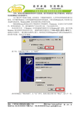
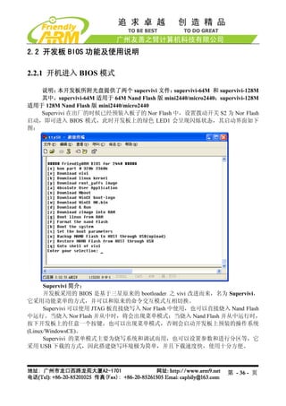
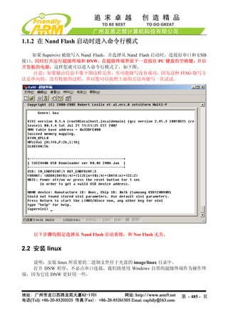
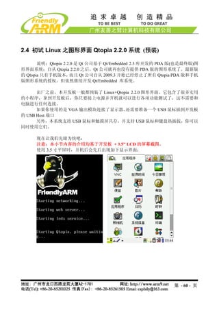
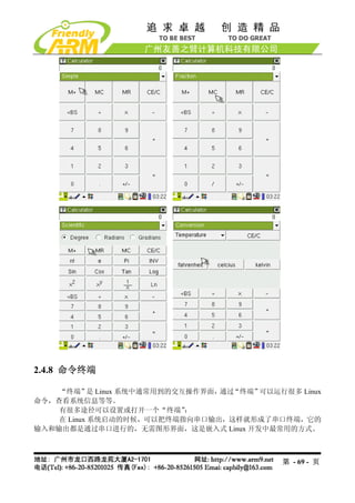
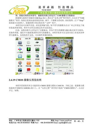
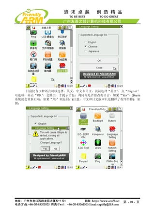
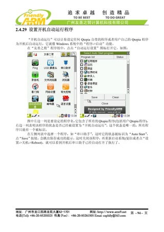
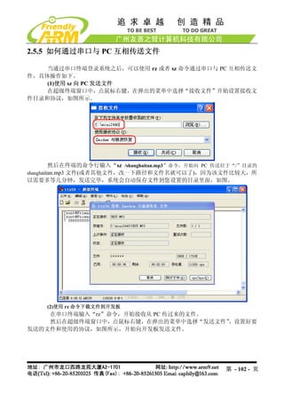
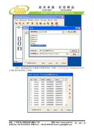
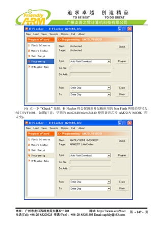
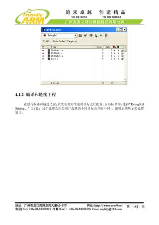
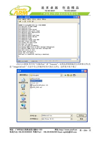
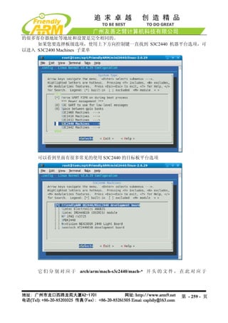
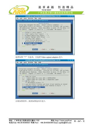
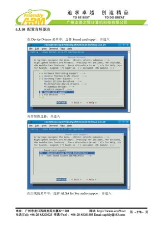
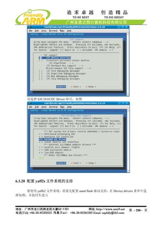
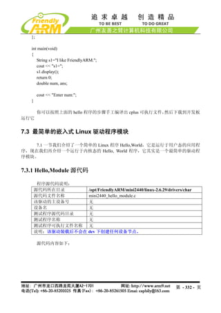
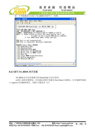
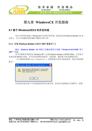
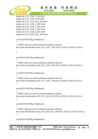
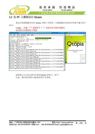
![2.2.3 功能主菜单说明
注意:以下通过 USB 下载的功能均配合 DNW 这个程序使用。
功能[x]:对 Nand Flash 进行默认分区,相当于执行命令行的 bon part 0 320k 2368k,此
命令仅对 Linux 系统有效。
功能[v]:通过 USB 下载 Linux bootloader 到 Nand Flash 的 bootloader 分区
功能[k]:通过 USB 下载 Linux 内核到 Nand Flash 的 kernel 分区
功能[y]:通过 USB 下载 yaffs 文件系统映象到 Nand Flash 的 root 分区
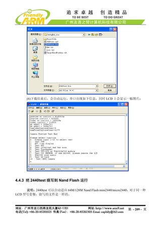
功能[a]:通过 USB 下载用户程序到 Nand Flash 中,一般这样的用户程序为 bin 可执
行文件, 2440test(需要支持超过 4K 限制)、
如 uCos2(开发板中带的 uCos2 支持 nand flash 启动)、
U-Boot 等;当然也可以是其他任意大小的 bin 程序。
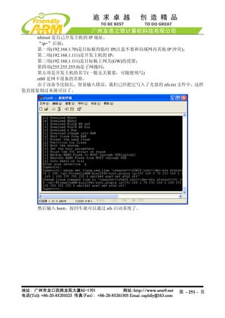
功能[n]:通过 USB 下载 WinCE 之启动程序 Nboot 到 Nand Flash 的 Block0
功能[l]:通过 USB 下载 WinCE 启动时的开机 Logo(bmp 格式的图片)
功能[w]:通过 USB 下载 WinCE 发行映象 NK.bin 到 Nand Flash
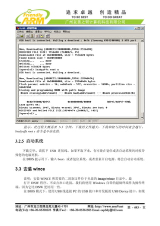
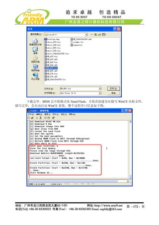
功能[d]:通过 USB 下载程序到指定内存地址(通过 DNW 的 Configuration->Option 选
项指定运行地址),并运行。对于本开发板,SDRAM 的物理起始地址是 0x30000000,结束地
址是 0x34000000,大小为 64Mbytes,另外 BIOS 本身占用了 0x33DE8000 以上的空间,因此
在用 BIOS 的 USB 下载功能时应指定地址在 0x30000000 - 0x33DE8000 之间。
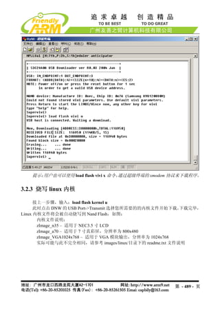
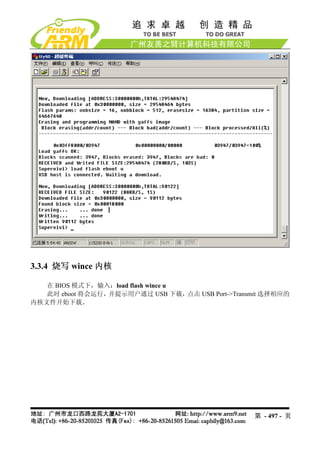
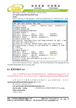
功 能 [z]: 通 过 USB 下 载 Linux 内 核 映 像 文 件 zImage 到 内 存 中 , 下 载 地 址 为
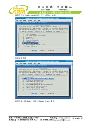
第 - 44 - 页](https://image.slidesharecdn.com/mini2440-um-20090817-091005002637-phpapp02/85/Mini2440-Um-20090817-44-320.jpg)
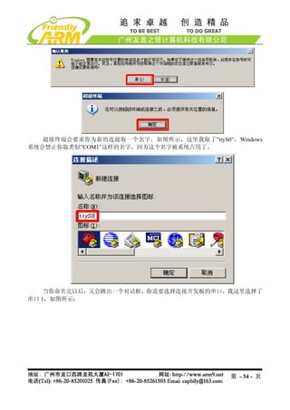
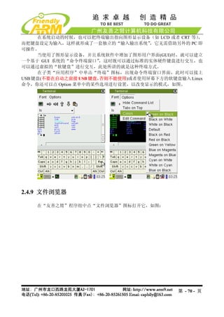
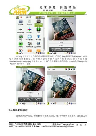
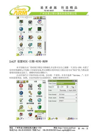
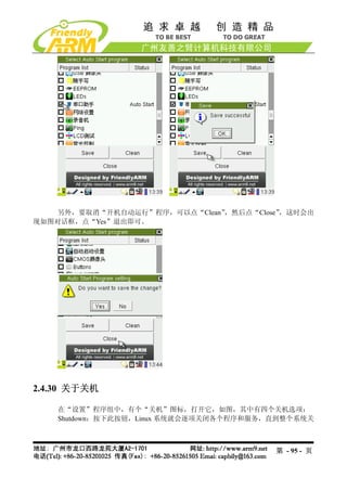
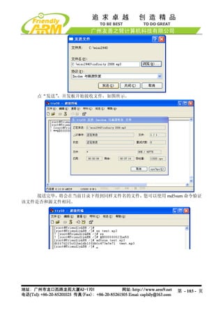
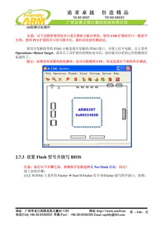
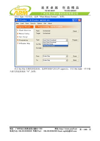
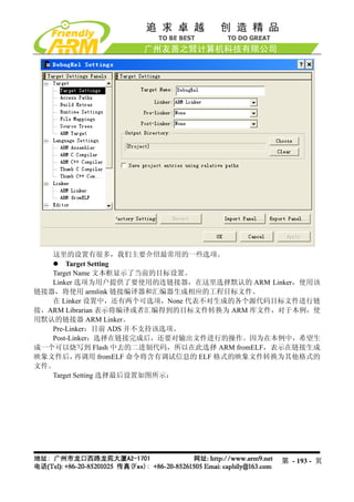
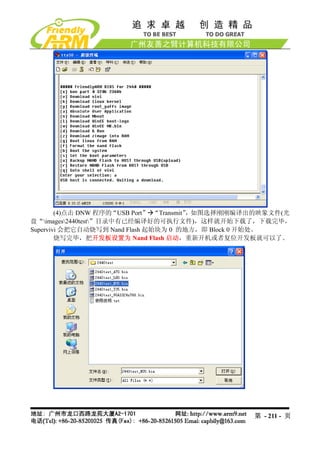
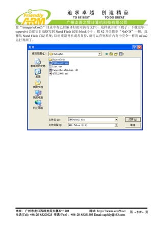
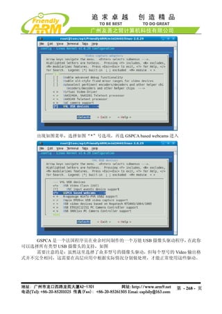
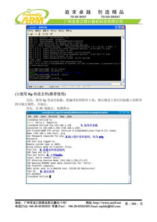
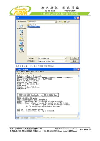
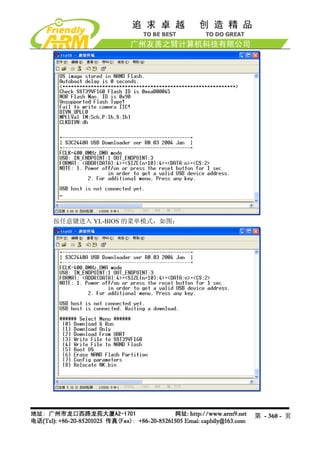
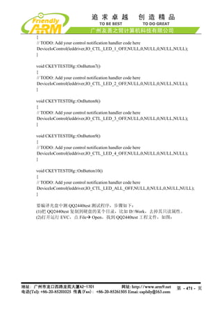
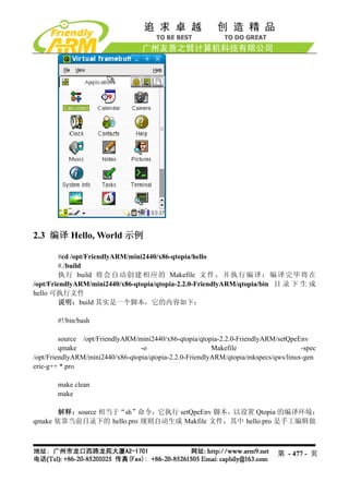
![0x30008000。
功能[g]: 运行内存中的 Linux 内核映像,该功能一般配合功能[z]一起使用。
功能[f]:擦除 Nand Flash,执行此功能将会擦除整片 Nand Flash 中的数据。(如果您是
第一次使用本开发板,请不必担心误操作,您可以根据本手册第三章的步骤恢复到出厂状态)
功能[b]:启动系统,如果烧入了 linux 或者 wince,执行从命令将自动辨认识别启动
系统。
功能[s]:设置 linux 启动参数,详细见子菜单说明
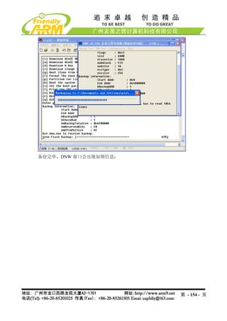
功能[u]:备份整个 Nand Flash 中的内容,通过 USB 上传到 PC 存储为一个文件,该
功能类似于 PC 系统中经常用的 Ghost 工具。
功能[r]:使用备份出来的文件恢复到 Nand Flash。
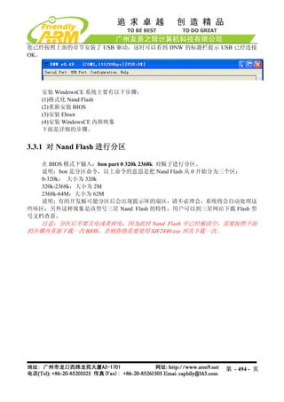
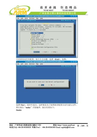
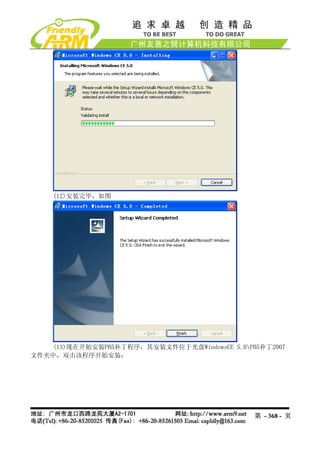
功能[q]:返回 vivi 的命令交互模式,如图
在交互模式下输入 menu 命令,则可以返回到菜单模式。
2.2.4 设置 linux 启动参数子菜单功能说明
通过该子菜单功能,可以更加灵活的启动 linux 系统,在 BIOS 主菜单执行功能号[s],
进入设置 linux 启动参数子菜单,如图:
第 - 45 - 页](https://image.slidesharecdn.com/mini2440-um-20090817-091005002637-phpapp02/85/Mini2440-Um-20090817-45-320.jpg)
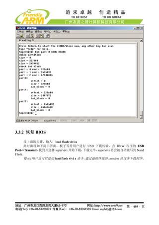
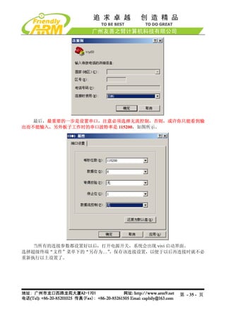
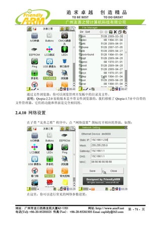
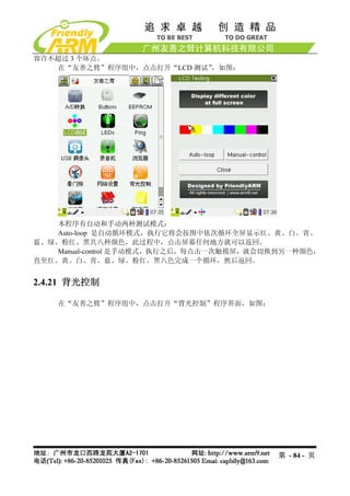
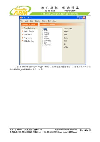
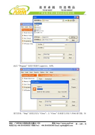
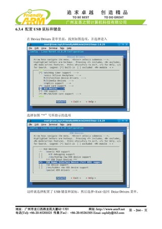
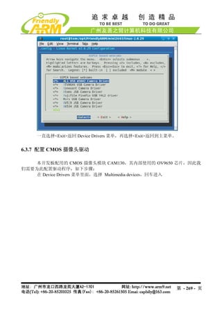
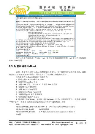
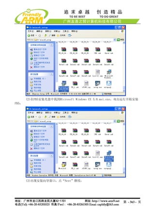
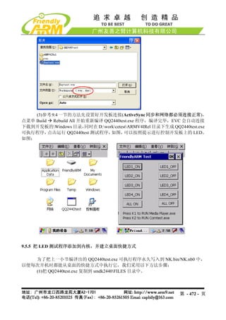
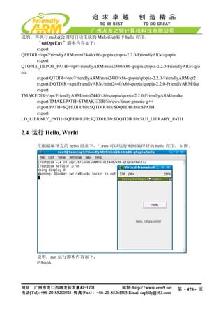
![(1)浏览当前参数设置[v]
输入“v”可以浏览当前启动参数设置情况:
第 - 46 - 页](https://image.slidesharecdn.com/mini2440-um-20090817-091005002637-phpapp02/85/Mini2440-Um-20090817-46-320.jpg)
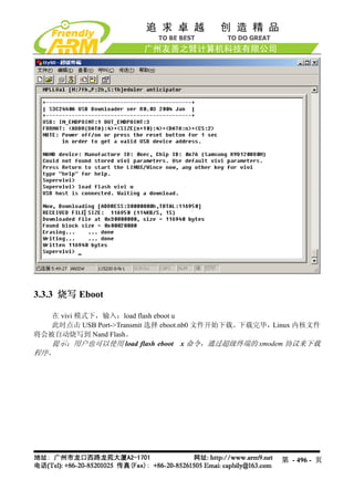
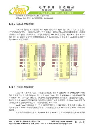
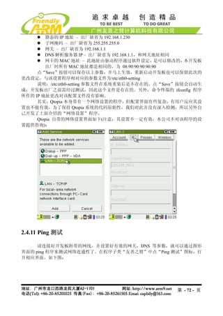
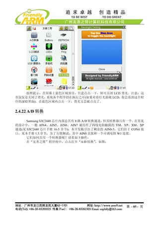
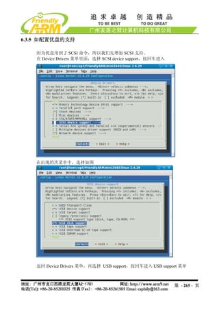
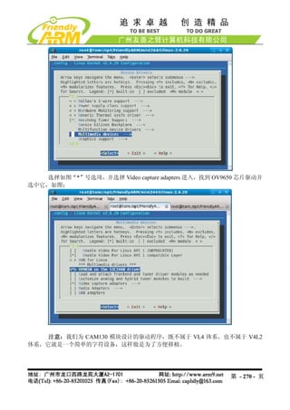
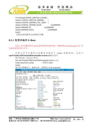
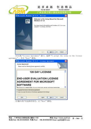
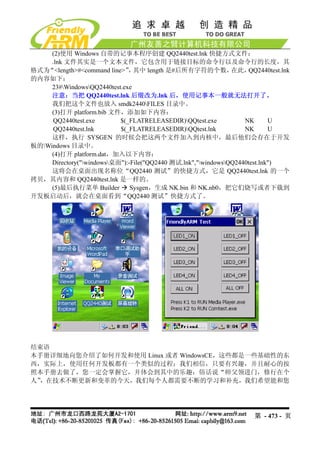
![(2)设置参数[s]
输入 “s” 可以对上面列出的参数进行设置,
, 比较常用的参数有(其他参数建议不要更改):
Mach_type
Linux command line
下面我们分别举例说明如何设置:
开发板默认的 MACH_TYPE 为 1999,假设你编译的内核使用的 MACH_TYPE 是 2000,
则可以通过修改 mach_type 参数来正常启动内核,根据提示先输入参数的名字“mach_type” ,
再输入参数值“2000”(引号不要输入),更改后记得输入“w”保存设置,如图:
Linux_cmd_line 是经常用到的一个内核启动参数,例如要把内核的启动信息和登录终
端改为串口 1(默认是串口 0) ,则这样修改:
通过浏览参数,可以看到原来的参数:
Linux_cmd_line:noinitrd root=/dev/mtdblock2 init=/linuxrc console=ttySAC0
输入“s”后,根据提示输入要修改的参数“linux_cmd_line” ,回车,再输入参数值为
(因为该参数串中有空格,因此需要输入双引号括起来):
“noinitrd root=/dev/mtdblock2 init=/linuxrc console=ttySAC1,115200”
如图所示:
第 - 47 - 页](https://image.slidesharecdn.com/mini2440-um-20090817-091005002637-phpapp02/85/Mini2440-Um-20090817-47-320.jpg)
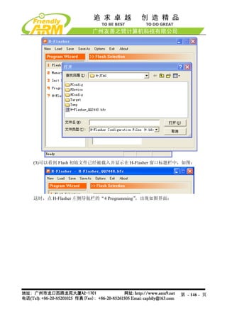
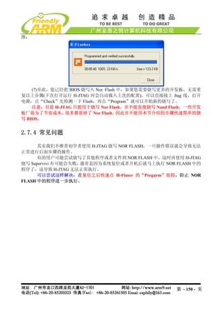
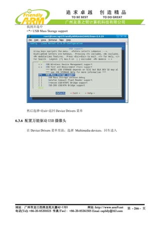
![这样系统启动的时候,内核的启动信息和登录信息都将在串口 1 出现,而 vivi 的输出
信息不会改变,还是从串口 0 出来。
(3)保存配置[w]
当设置更改之后,可以输入“w”保存所作的更改。
(4)恢复默认值[r]
输入“r”可以恢复出厂时的内核启动参数。
(5)返回主菜单[q]
输入“q”可以返回 BIOS 功能主菜单。
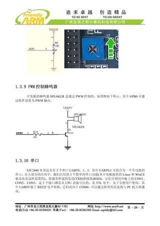
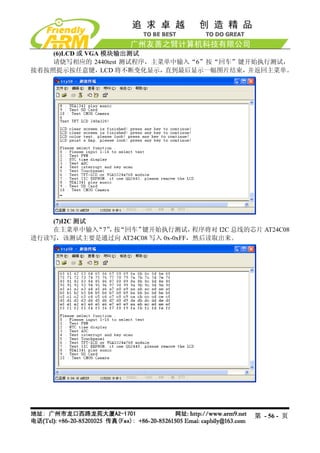
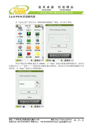
2.3 非操作系统下的外围资源测试
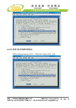
在非操作系统下,主要测试 PWM 控制蜂鸣器,RTC 实时时钟测试,AD 转换测试,
按键,触摸屏,各种 LCD,红外测试,I2C 总线测试,音频输入与输出,SD 卡功能。
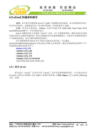
2.3.1 下载运行测试程序
说明:2440test 是一个裸机测试程序,它不是一个操作系统,该程序由三星原厂的同
名文件修改而来,我们根据实际情况,更改了输出菜单和各项测试内容,使其更加简洁明了,
第 - 48 - 页](https://image.slidesharecdn.com/mini2440-um-20090817-091005002637-phpapp02/85/Mini2440-Um-20090817-48-320.jpg)
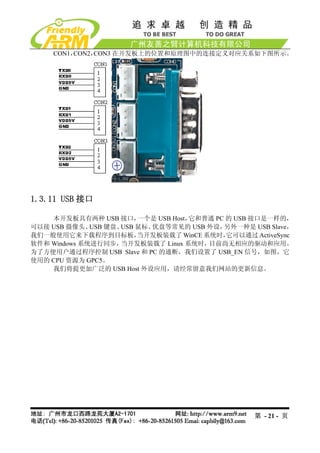
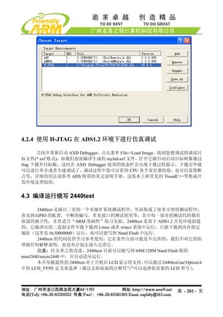
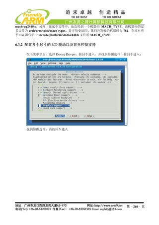
![为了方便用户测试和使用, 我们分别编译出了针对不同类型 LCD 显示输出的可执行二进制文
件(见下表),用户使用本节的步骤通过 USB 下载到内存中即可运行,区别之处在于默认显示
LCD 显示输出的类型不同;实际上它们都是使用相同的代码编译出的,只需在头文件中更改
一下 LCD 类型(2440testincOption.h 中“LCD_TYPE” 定义)即可。
文件名 说明 备注
2440test_N35.bin 默认显示输出支持 NEC3.”LCD (1) 因为它们的代码都是相
2440test_T35.bin 默认显示输出支持统宝 3.5”LCD 同的,以下我们把这几个
2440test_L80.bin 默认显示输出支持 Sharp 8”LCD(或兼 针对不同显示输出的测
容) 试 文 件 统 称 为
2440test_A70.bin 默认显示输出支持群创 7”LCD 2440test.bin
2440test_VGA1024x768.bin 默 认 显 示 输 出 支 持 VGA( 分 辨 率 : (2) 2440test 可 以 兼 容
1024x768@70Hz) 64M/128M 友 善 之 臂
2440 开发板
在光盘“images2440test”目录中找到 2440test.bin 文件,通过 BIOS 下载运行该测试
程序,步骤如下:
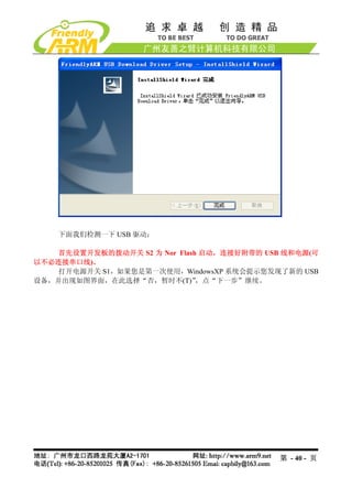
(1)连接好开发板电源,串口线,USB 线,并设置拨动开关 S2 为 Nor Flash 启动系统,
分别打开串口超级终端和 DNW,上电启动开发板。
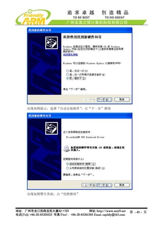
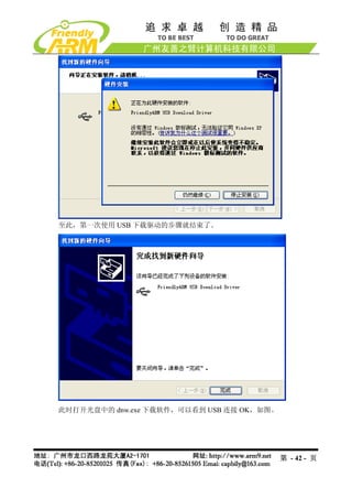
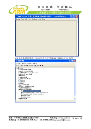
(2)保证 USB 驱动已经安装好(前面已经详细介绍了 USB 驱动的安装方法),这时可以
看到 DNW 的标题栏显示[USB:OK],如果没有安装好驱动会显示[USB:x],如图所示:
(3)点 DNW 菜单 Configuration,设置 USB 下载运行地址为 0x30000000
第 - 49 - 页](https://image.slidesharecdn.com/mini2440-um-20090817-091005002637-phpapp02/85/Mini2440-Um-20090817-49-320.jpg)
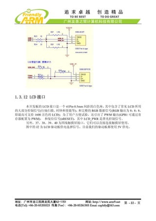
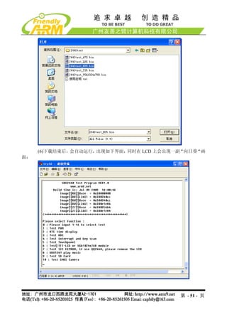
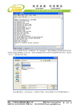
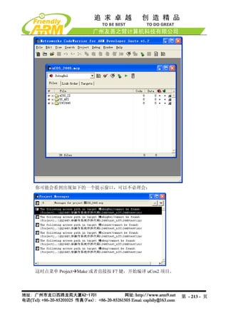
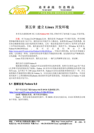
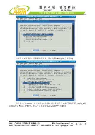
![(4)这时在超级终端的 BIOS 功能菜单中选择功能号[d],出现 USB 下载等待提示信息:
(5)点击 DNW 程序的“USB Port” “Transmit”,选择 2440test.bin 这个映象文件(在
光盘的 images2440test目录下面),接着点“打开”,这样就开始下载了。
第 - 50 - 页](https://image.slidesharecdn.com/mini2440-um-20090817-091005002637-phpapp02/85/Mini2440-Um-20090817-50-320.jpg)


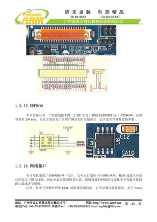
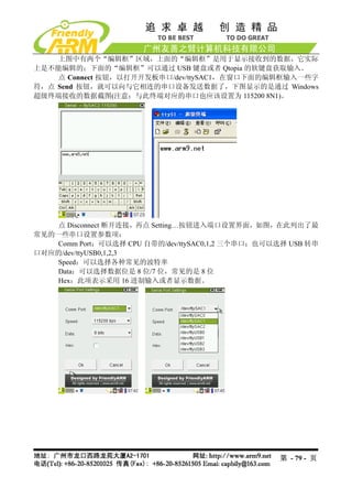
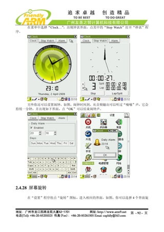
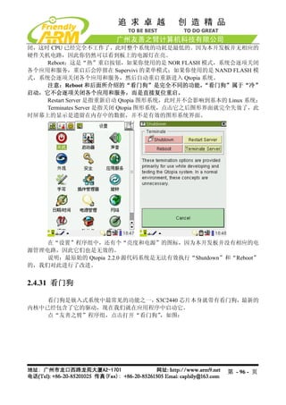
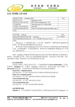
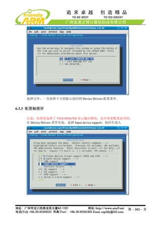
![2.4.16 串口助手
提示:在使用该程序之前请连接好你需要测试的串口
开发板上的 CON1,2,3 分别对应 CPU 的 UART0,1,2,其中 UART0 已经转换为
RS232 电平,并通过 DB9 插座 COM0 输出,它在启动时已经被设置为 console 终
端,因此不能直接使用该程序测试。其他两个串口 CON2,3 需要增加 RS232 转换
才可以和 PC 的串口连接使用。(本公司提供了型号为“OneCom”RS232 转换模
块,如图),连接 PC 时请注意你使用的串口线类型(交叉或直连);不管你使用的
是何种串口线,你也可以根据实际情况设置 OneCom 模块上的 COM.2 和 COM.3
跳线。
本程序也支持市面上常见的 USB 转串口线,因为目前的笔记本大都没有串口,
为了方便开发,我们的很多代理都提供了类似的转接线。把 USB 转串口线接到
开发板的 USB Host 端口上,你就可以扩充开发板的串口了。它对应的设备名一
般为/dev/ttyUSB0,1,2,3 等,这意味着你可以通过 USB Hub 扩展多个 USB 转串口。
在“友善之臂”程序组中点“串口助手”图标,打开相应的程序界面,如图:
从该程序窗口的标题可以看到,默认设置为“ttySAC1 115200 8N1 [C]”,它表示默认
端口的设置:
- 串口设备:/dev/ttySAC1,它对应 CPU 的第二个串口 UART1
- 波特率:115200
- 数据位:8
- 流控制:无
- 停止位:1
- [C]:表示字符模式,如果是[H]则表示 16 进制模式
第 - 78 - 页](https://image.slidesharecdn.com/mini2440-um-20090817-091005002637-phpapp02/85/Mini2440-Um-20090817-78-320.jpg)
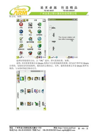
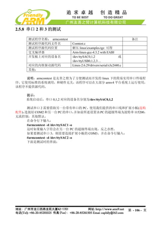
![下命令:
#/etc/rc.d/init.d/leds stop
该命令将停止 led-player 对 led 的操纵。led 的使用方法如下:
[root@fa /]# led
Usage: leds led_no 0|1
led_no 是要操作的 led(可为 0,1,2,3),0 和 1 分别代表关闭和点亮。
#led 2 1
将点亮 LED3
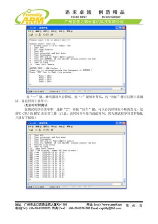
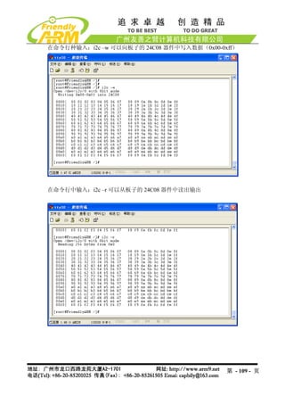
2.5.7 测试板上的按键
测试程序名称: buttons 备注
测试程序源代码文件名 Buttons_test.c
测试程序源代码位置 解压 linuxexamples.tgz 可得
交叉编译器 Arm-linux-gcc-4.3.2 with EABI
开发板上对应的设备名 /dev/buttons
对应的内核驱动源代码 Linux-2.6.29/drivers/char/mini2440_buttons.c
其他:
在命令行输入“buttons”命令,然后按开发板上的按键,可以显示对应的键值,如图
第 - 105 - 页](https://image.slidesharecdn.com/mini2440-um-20090817-091005002637-phpapp02/85/Mini2440-Um-20090817-105-320.jpg)
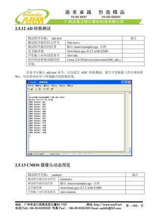
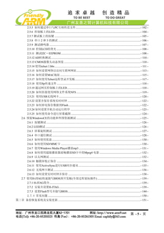
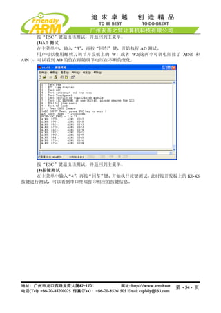
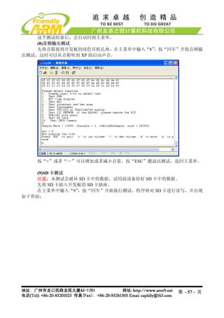
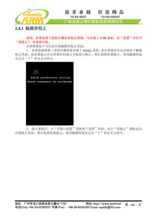
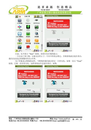
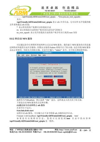
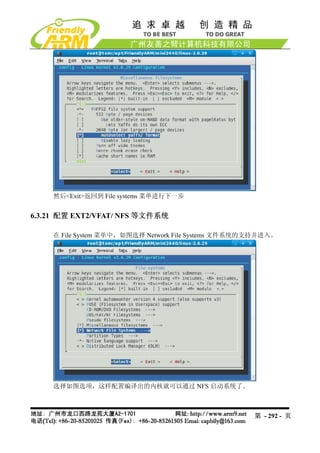
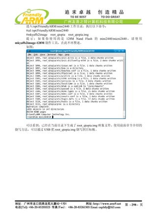
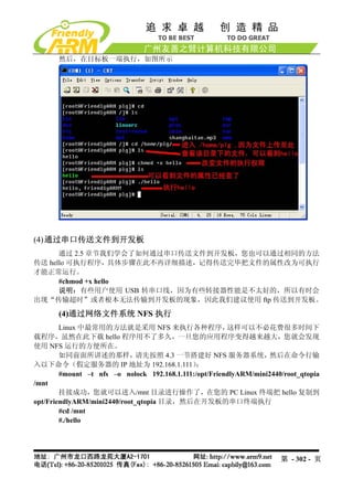
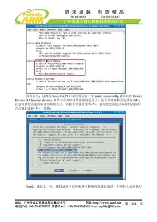
![2.5.21 使用 USB 无线网卡
Linux-2.6.29 内核已经自带了部分 USB 无线网卡的驱动,其中包括目前最流行、性价
比最高的 TP-Link USB WiFi 无线网卡:TL-WN321G+,本开发板的缺省内核映象已经加入了
本模块的支持。
提示:本手册的 6.3 章节有关于在内核中配置无线网卡驱动的说明
把 USB 无线网卡插入开发板,会出现如下信息:
[root@FriendlyARM /]# usb 1-1: new full speed USB device using s3c2410-ohci and
address 2
usb 1-1: New USB device found, idVendor=148f, idProduct=2573
usb 1-1: New USB device strings: Mfr=1, Product=2, SerialNumber=0
usb 1-1: Product: 54M.USB.......
usb 1-1: Manufacturer: Ralink
usb 1-1: configuration #1 chosen from 1 choice
wmaster0 (rt73usb): not using net_device_ops yet
wlan0 (rt73usb): not using net_device_ops yet
[root@FriendlyARM /]#
第 - 120 - 页](https://image.slidesharecdn.com/mini2440-um-20090817-091005002637-phpapp02/85/Mini2440-Um-20090817-120-320.jpg)
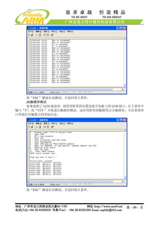
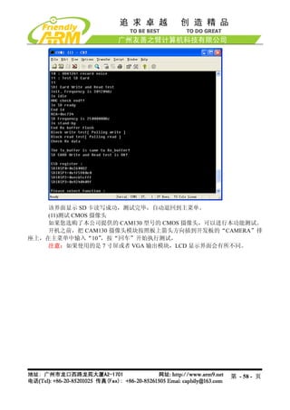
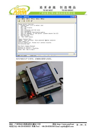
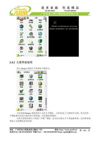
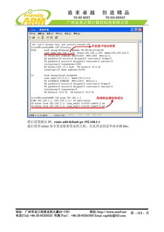
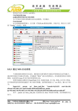
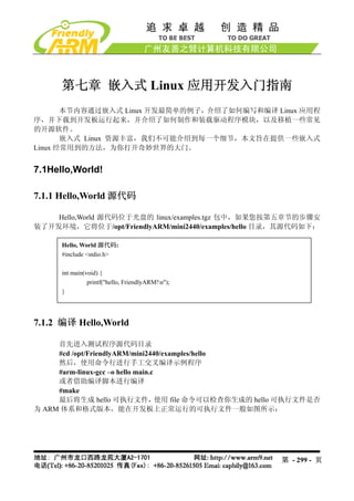
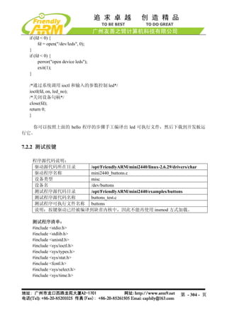
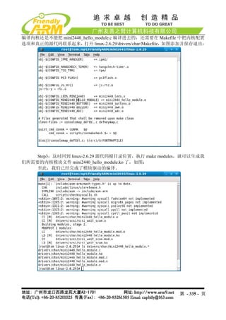
![这说明已经识别到该无线网卡,然后通过步骤命令开始配置。
(1)首先关闭开发板的有线网卡 DM9000
[root@FriendlyARM /]# ifconfig eth0 down
(2)加载 USB WiFi 无线网卡
[root@FriendlyARM /]# ifconfig wlan0 up
rt73usb 1-1:1.0: firmware: requesting rt73.bin
[root@FriendlyARM /]#
(3)扫描可用的无线网络
[root@FriendlyARM /]# iwlist scanning | grep ESSID
lo Interface doesn't support scanning.
eth0 Interface doesn't support scanning.
wmaster0 Interface doesn't support scanning.
ESSID:"FRIENDLY-ARM"
ESSID:"NETGEAR"
ESSID:"TP-LINK"
[root@FriendlyARM /]#
(4)选择要连接的无线网络
[root@FriendlyARM /]# iwconfig wlan0 essid "FRIENDLY-ARM"
(5)输入该网络的安全密码
[root@FriendlyARM /]# iwconfig wlan0 key s:12345
(6)连接到指定的 AP(无线路由)
[root@FriendlyARM /]# iwconfig wlan0 ap auto
(7)设置无线网卡的 IP 地址
[root@FriendlyARM /]# ifconfig wlan0 192.168.1.120
(8)使用 ping 命令检测无线网连通状况
[root@FriendlyARM /]# ping 192.168.1.1
PING 192.168.1.1 (192.168.1.1): 56 data bytes
64 bytes from 192.168.1.1: seq=0 ttl=64 time=42.804 ms
64 bytes from 192.168.1.1: seq=1 ttl=64 time=5.020 ms
64 bytes from 192.168.1.1: seq=2 ttl=64 time=5.021 ms
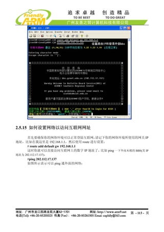
以上整个过程如下所示:
[root@FriendlyARM /]# usb 1-1: new full speed USB device using s3c2410-ohci and
address 2
usb 1-1: New USB device found, idVendor=148f, idProduct=2573
usb 1-1: New USB device strings: Mfr=1, Product=2, SerialNumber=0
usb 1-1: Product: 54M.USB.......
usb 1-1: Manufacturer: Ralink
usb 1-1: configuration #1 chosen from 1 choice
第 - 121 - 页](https://image.slidesharecdn.com/mini2440-um-20090817-091005002637-phpapp02/85/Mini2440-Um-20090817-121-320.jpg)
![wmaster0 (rt73usb): not using net_device_ops yet
wlan0 (rt73usb): not using net_device_ops yet
[root@FriendlyARM /]# ifconfig eth0 down
[root@FriendlyARM /]# ifconfig wlan0 up
rt73usb 1-1:1.0: firmware: requesting rt73.bin
[root@FriendlyARM /]# iwconfig wlan0 key s:12345
[root@FriendlyARM /]# iwconfig wlan0 essid "FRIENDLY-ARM"
[root@FriendlyARM /]# iwconfig wlan0 ap auto
[root@FriendlyARM /]# ifconfig wlan0 192.168.1.120
[root@FriendlyARM /]# ping 192.168.1.1
PING 192.168.1.1 (192.168.1.1): 56 data bytes
64 bytes from 192.168.1.1: seq=0 ttl=64 time=42.804 ms
64 bytes from 192.168.1.1: seq=1 ttl=64 time=5.020 ms
64 bytes from 192.168.1.1: seq=2 ttl=64 time=5.021 ms
^C
--- 192.168.1.1 ping statistics ---
3 packets transmitted, 3 packets received, 0% packet loss
round-trip min/avg/max = 5.020/17.615/42.804 ms
[root@FriendlyARM /]#
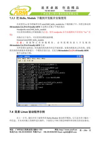
2.5.22 设置并保存系统实时时钟
Linux 中更改时间的方法一般使用 date 命令,为了把 S3C2440 内部带的时钟与 linux 系统时钟同
步,一般使用 hwclock 命令,下面是它们的使用方法:
(1) date -s 042916352007 #设置时间为 2007-04-29 16:34
(2) hwclock -w #把刚刚设置的时间存入 S3C2440 内部的 RTC
(3).开机时使用 hwclock -s 命令可以恢复 linux 系统时钟为 RTC, 一般把该语句放入
/etc/init.d/rcS 文件自动执行。
注意:我们提供的系统已经把 hwclock –s 命令写入 rcS 文件。
2.5.23 如何掉电保存数据到 Flash
由于本系统采用了可读写文件系统 yaffs(在嵌入式系统中,专门管理 Flash 存储器的
一种文件系统),因此可以很方便的动态保存数据,掉电后不会丢失。开机后在串口终端运行
以下命令:
#cp / shanghaitan.mp3 /home/plg
此时将在/home/fa 目录下复制一个同样的文件,然后关机,重新开启系统,可以查看
到/home/plg 目录下的文件依然存在。
第 - 122 - 页](https://image.slidesharecdn.com/mini2440-um-20090817-091005002637-phpapp02/85/Mini2440-Um-20090817-122-320.jpg)

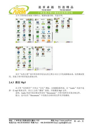
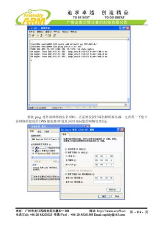
![(2) 选择功能号[u]开始备份 Nand Flash 内容到文件,如图所示:
第 - 152 - 页](https://image.slidesharecdn.com/mini2440-um-20090817-091005002637-phpapp02/85/Mini2440-Um-20090817-152-320.jpg)
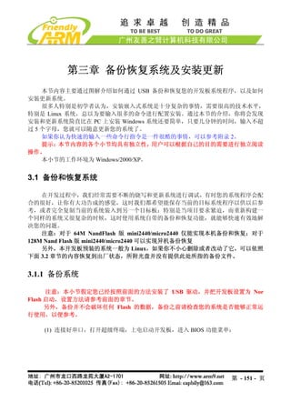
![(3) 打开 DNW 程序,接上 USB 电缆,如果 DNW 标题栏提示[USB:OK],说明 USB
连接成功,这时选择 DNW 菜单的 Usb Port Backup NandFlash to File,如图所示:
跳出文件保存窗口,选择所要保存文件的位置,并命名(这里保存文件为 backup.bin),
如图:
系统开始备份,备份的进度如图所示:
第 - 153 - 页](https://image.slidesharecdn.com/mini2440-um-20090817-091005002637-phpapp02/85/Mini2440-Um-20090817-153-320.jpg)
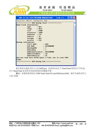
![(2) 选择功能号[r]开始使用备份文件恢复整个 Nand Flash,如图所示:
第 - 157 - 页](https://image.slidesharecdn.com/mini2440-um-20090817-091005002637-phpapp02/85/Mini2440-Um-20090817-157-320.jpg)
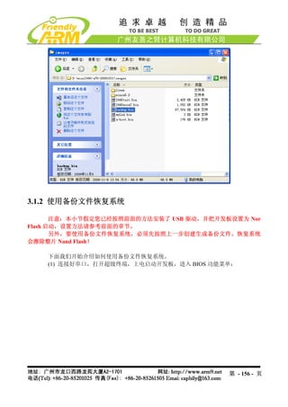
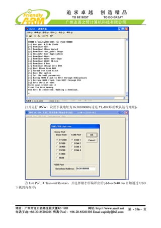
![(3) 打开 DNW 程序,接上 USB 电缆,如果 DNW 标题栏提示[USB:OK],说明 USB
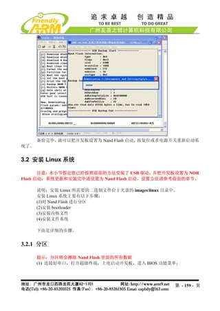
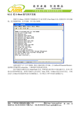
连接成功,这时选择 DNW 菜单的 Usb Port Transmit/Restore,如图所示:
跳出文件选择窗口,选择要使用的备份文件(如上一步骤所生成的 backup.bin), “打
点
开”开始恢复系,如图所示:
第 - 158 - 页](https://image.slidesharecdn.com/mini2440-um-20090817-091005002637-phpapp02/85/Mini2440-Um-20090817-158-320.jpg)
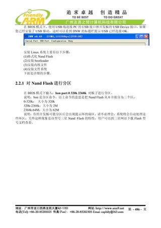
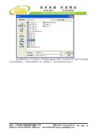
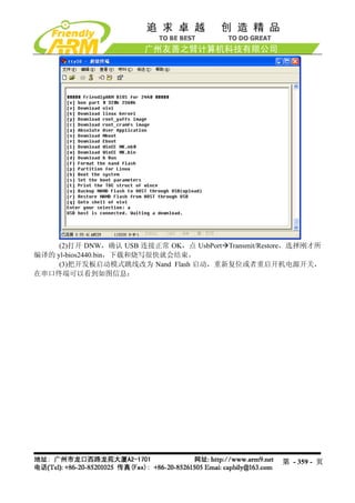
![(2) 选择功能号[x]开始对 Nand Flash 进行分区,如图所示。
说明:有的 Nand Flash 分区时会出现坏区报告提示,因为 supervivi 会对坏区做检测
记录,因此这将不会影响板子的正常使用。
提示:普通的 Nand Flash 并不能保证所有扇区都是完好的,如果有坏区,系统软件会
对它们做检测处理,而不会影响整个软件系统的使用。保证完全无坏区的 Nand Flash 另有型
号,请参考光盘中的 Flash 选项指南(Samsung_Nand_Flash.pdf),这种 Flash 一般没有现货,
而且订货周期长,价格昂贵,一般场合很少用到;其他品牌的 Nand Flash 也与此类似。
第 - 160 - 页](https://image.slidesharecdn.com/mini2440-um-20090817-091005002637-phpapp02/85/Mini2440-Um-20090817-160-320.jpg)
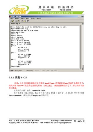
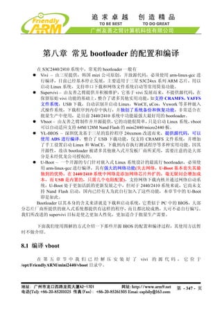
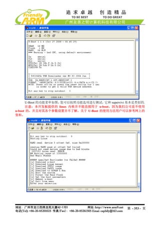
![3.2.2 安装 bootloader
注意:老用户必须先更新 NOR FLASH 里面的 BIOS 为 Supervivi-64M 才可以进行
下面的步骤。
我们针对 Linux 系统提供了两种 bootloader:vboot 和 supervivi。
其中 vboot 是一个十分简易的开源软件,由友善之臂设计制作,它可以兼容启动
64M/128M Nand Flash 版 mini2440/micro2440;之前我们使用的是 vivi,它是由三星原厂提供
的,它的结构复杂,只能启动 64M 版本,因此我们目前已经弃用了。
Supervivi 由 vivi 发展而来,针对 64M 和 128M 开发板分别有 supervivi-64M 和
supervivi-128M 两个文件,它们的用法和功能是一样的,我们统称为 supervivi,只是在选择
具体的文件时有所区分;它并不是开源的。
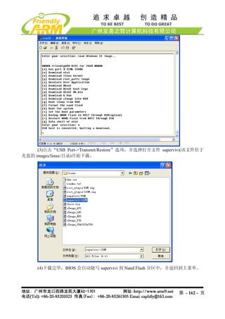
(1) 打开 DNW 程序,接上 USB 电缆,如果 DNW 标题栏提示[USB:OK],说明 USB
连接成功,这时根据菜单选择功能号[v]开始下载 supervivi
第 - 161 - 页](https://image.slidesharecdn.com/mini2440-um-20090817-091005002637-phpapp02/85/Mini2440-Um-20090817-161-320.jpg)
![3.2.3 安装 Linux 内核
说明:Linux 内核可以自适应 64M/128M Nand Flash 版 mini2440/micro2440
(1)在 BIOS 主菜单中选择功能号[k],开始下载 linux 内核 zImage
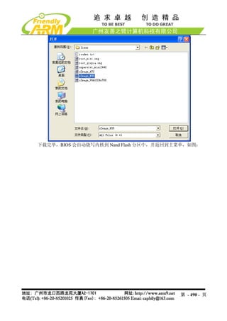
(2) 点击“USB Port->Transmit”选项,并选择打开相应的内核文件 zImage(该文件位
于光盘的 imageslinux目录)开始下载。
内核文件说明:
zImage_n35 – 适用于 NEC3.5”LCD
zImage_T35 – 适用于统宝 3.5”LCD
zImage_L80 – 适用于 Sharp 8”LCD(或兼容)
zImage_a70 – 适用于 7 寸真彩屏,分辨率为 800x480
zImage_VGA1024x768 – 适用于 VGA 模块输出,分辨率为 1024x768
实际可能与此不完全相同,请参考 imageslinux 目录下的 readme.txt 文件说明
第 - 163 - 页](https://image.slidesharecdn.com/mini2440-um-20090817-091005002637-phpapp02/85/Mini2440-Um-20090817-163-320.jpg)
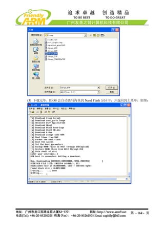
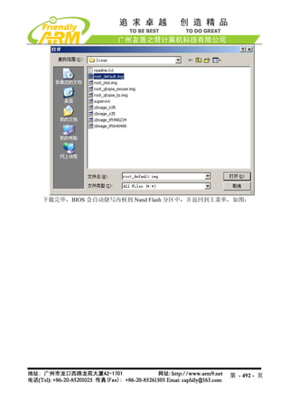
![3.2.4 安装根文件系统
说明:针对 64M/128M mini2440/micro2440,有不同的文件系统烧写映象文件:
root_qtopia-64M.img 和 root_qtopia-128M.img,实际上它们的内容都是完全相同的,只是制作
工具(mkyaffs2image)不同,我们把文件系统统称为 root-qtopia.img。
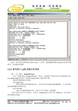
(1)在 BIOS 主菜单中选择功能号[y],开始下载 yaffs 根文件系统映象文件
(2) 点击“USB Port->Transmit/Restore”选项,并选择打开相应的文件系统映象文件
root_qtopia.img(该文件位于光盘的 imageslinux 目录)开始下载。
根文件系统映象文件说明:
root_qtopia-64M.img
-缺省安装的文件系统映象文件,可以同时支持 USB 鼠标和触摸屏,并自动识别
VGA 模块输出和 NFS 启动,适用于 64M Nand Flash 版 mini2440/micro2440
root_qtopia-128M.img
-缺省安装的文件系统映象文件,可以同时支持 USB 鼠标和触摸屏,并自动识别
VGA 模块输出和 NFS 启动,适用于 128M Nand Flash 版 mini2440/micro2440
第 - 165 - 页](https://image.slidesharecdn.com/mini2440-um-20090817-091005002637-phpapp02/85/Mini2440-Um-20090817-165-320.jpg)
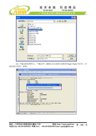
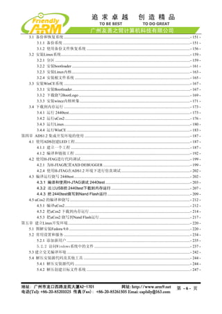
![提示:此过程大概需要 2-3 分钟,下载的文件越大,下载和烧写的时间就会越长。
注意:下载完毕,请拔下 USB 连接线,如果不取下来,有可能在复位或者启动系统
的时候导致您的电脑死机。
在 BIOS 主菜单中选择功能号[b],将会启动系统。
如果您把开发板的启动模式设置为 Nand Flash 启动,则系统会在上电后自动启动。
3.3 安装 WinCE 系统
说明:安装 WinCE 所需要的二进制文件位于光盘的“imageswince5.0”目录中
安装 WindowsCE 系统主要有以下步骤:
(1)安装 bootloader
(2)安装 BootLogo(bmp 格式)
(3)安装 WindowsCE 内核映象
下面是详细的步骤:
提示:请先连接好串口,打开超级终端,上电启动开发板,进入 BIOS 功能菜单
3.3.1 安装 Bootloader
注意:老用户必须先更新 NOR FLASH 里面的 BIOS 为 Supervivi-64M 才可以进行
下面的步骤。
本开发板提供了两种 bootloader 均可启动 WINCE:supervivi 和 nboot.bin,它们的说
明如下:
Supervivi-64M 或 Nboot.bin
Supervivi-128M
二进制映象文件的位置 imageswince5.0 imageswince5.0
源代码位置 无 WindowsCE5.0NBOOT
项目文件 无 Nboot.mcp
编译器 Arm-linux-gcc ADS1.2
功能描述 见前面章节 BIOS 功能 支持快速启动 WindowsCE(一般 6-10 秒,
介绍。 视内核大小而定)
注意: supervivi 的总体 支持开机 Logo(通过 USB 下载普通的
启动速度比 nboot 要快 bmp 格式真彩图片)
2-3 秒,但不支持开机 带进度条(用户可根据源代码配置文件自
Logo 和进度条 行定义进度条的各个属性:颜色、长宽、
起始位置等)
说明:
第 - 167 - 页](https://image.slidesharecdn.com/mini2440-um-20090817-091005002637-phpapp02/85/Mini2440-Um-20090817-167-320.jpg)
![supervivi 由友善之臂维护和发展,不提供源代码
NBOOT 的配置和编译见 4.6 章节
此处提供的 Nboot 分别有 Nboot_N35.bin、Nboot_T35.bin、Nboot_L80.bin、
Nboot_A70.bin、Nboot_VGA1024x768.bin,它们分别对应于不同的 LCD 型
号,因为 Nboot 并不能自动识别 LCD,为了用户使用方便,我们根据配置文
件分别做了编译。
下面以 Nboot_N35.bin 为例(以下简称 Nboot.bin),介绍 Nboot.bin 的下载烧写步骤:
(1) 打开 DNW 程序,接上 USB 电缆,如果 DNW 标题栏提示[USB:OK],说明 USB
连接成功,这时根据菜单选择功能号[n]开始下载 Nboot.bin
(3)点击“USB Port->Transmit”选项,并选择打开文件 Nboot.bin(该文件位于光盘的
imageswince5.0 目录)开始下载。
第 - 168 - 页](https://image.slidesharecdn.com/mini2440-um-20090817-091005002637-phpapp02/85/Mini2440-Um-20090817-168-320.jpg)
![(4)下载完毕,BIOS 会自动把 Nboot.bin 烧写到 Nand Flash 的 Block 0
3.3.2 下载烧写 BootLogo
说明: WindowsCE 系统的启动过程有两种 Logo: BootLogo 和 StartLogo。其中 BootLogo
是由 Nboot 加载显示的, 用户可以通过修改 Nboot 的源代码调整 BootLogo 的显示位置和背景
色 ; StartLogo 则 属 于 BSP 的 一 部 分 , 它 是 一 个 数 组 文 件 (StartLogo.c) , 位 于
“mini2440SrcKernelOal”目录,由该目录下的 init.c 文件实现加载显示,StartLogo.c 文件可
以通过本光盘中的 StartLogoMaker.exe 工具制作生成。
另外, BootLogo 通过 Supervivi 的[l]功能下载烧写到 Nand Flash, 它必须是真彩 bmp
图片(一般 bmp 都是真彩的),并且不能大于 380K。
(1)在 BIOS 主菜单中选择功能号[l],开始下载 bmp 图片作为 BootLogo(光盘中已经准
备好一个 BootLogo.bmp 图片)
第 - 169 - 页](https://image.slidesharecdn.com/mini2440-um-20090817-091005002637-phpapp02/85/Mini2440-Um-20090817-169-320.jpg)

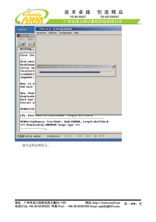
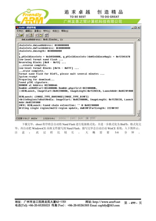
![3.3.3 安装 wince 内核映象
说明:Supervivi 已经集成了 WinCE 内核烧写功能,不需要加载其他的跳板文件(诸如
Eboot 等),Supervivi 先通过 USB 下载 NK.bin 到内存中,然后格式化 Nand Flash,再创建系
统分区(NK.bin 所占用的 NandFlash 空间,BINFS 格式,为只读)和用户分区(对应于 WinCE
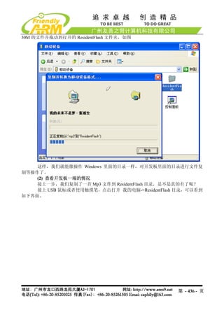
启动后的 ResidentFlash 目录,FAT 格式,可读写)
我们提供的 WinCE 系统可以自适应支持 64M/128M mini2440/micro2440, 因此烧写的
WinCE 内核文件是一样的。
(1)在 BIOS 主菜单中选择功能号[w],开始下载 WINCE 内核
(2) 点击“USB Port->Transmit/Restore”选项,并选择打开相应的内核文件 NK.bin(该
文件位于光盘的imageswince5.0 目录)开始下载。
WINCE 内核文件说明:
NK_N35.bin –适用于 NEC 3.5" LCD
NK_T35.bin – 适用于统宝 3.5”LCD
NK_L80.bin – 适用于 Sharp 8”LCD(或兼容)
NK_A70.bin – 适用于 7”LCD
NK_VGA1024x768.bin – 适用于 VGA 模块输出,分辨率为 1024x768
实际可能与此不完全相同,请参考 imageswince5.0 目录下的 readme.txt 文件说明
第 - 171 - 页](https://image.slidesharecdn.com/mini2440-um-20090817-091005002637-phpapp02/85/Mini2440-Um-20090817-171-320.jpg)
![3.4 下载到内存运行
Supervivi 支持很多程序下载到内存中运行,例如 2440test、uCos2、Linux 内核、WinCE
内核等。对于简单的系统,一般可以通过 USB 下载到内存中运行调试,对于比较高级完善的
系统则烧写到 Nand Flash 中运用其本身的功能进行进一步的调试。
3.4.1 运行 2440test
文件信息 备注
在光盘中的位置 光盘images2440test 2440test_N35.bin 适用于 NEC3.5”LCD
2440test_T35.bin 适用于统宝 3.5”LCD
2440test_A70.bin 适用于群创 7”LCD
2440test_L80.bin 适 用 于 Sharp
8”LCD(或兼容)
2440test_VGA1024x768.bin 适 用 于
VGA 模块,分辨率 1024x768
指定下载运行地址 0x30000000
对应的源代码位置 非操作系统示例代码2440test
项目名称 2440test.mcp 默认项目使用 NEC3.5 寸屏
编译工具 ADS1.2
说明:
若要烧写到 Nand Flash 运行,需选择 supervivi 的[a]功能,无需指定下载地址
通过修改“非操作系统示例代码2440testincOption.h”中 LCD_TYPE 的定义,
可以编译出可以编译出适用于不同 LCD 型号的目标文件
(1)连接好开发板电源,串口线,USB 线,并设置拨动开关 S2 为 Nor Flash 启动系统,
分别打开串口超级终端和 DNW,上电启动开发板。
(2)保证 USB 驱动已经安装好(前面已经详细介绍了 USB 驱动的安装方法),这时可以
看到 DNW 的标题栏显示[USB:OK],如果没有安装好驱动会显示[USB:x],如图所示:
第 - 173 - 页](https://image.slidesharecdn.com/mini2440-um-20090817-091005002637-phpapp02/85/Mini2440-Um-20090817-173-320.jpg)
![(3)点 DNW 菜单 Configuration,设置 USB 下载运行地址为 0x30000000
(4)这时在超级终端的 BIOS 功能菜单中选择功能号[d],出现 USB 下载等待提示信息:
第 - 174 - 页](https://image.slidesharecdn.com/mini2440-um-20090817-091005002637-phpapp02/85/Mini2440-Um-20090817-174-320.jpg)
![同时在 LCD 上会出现一副图片显示。
3.4.2 运行 uCos2
文件信息 备注
在光盘中的位置 imagesuCos22440uCos2.bin 2440uCos2_N35.bin 适用于 NEC3.5”LCD
2440uCos2_T35.bin 适用于统宝 3.5”LCD
2440uCos2_L80.bin 适 用 于 Sharp
8”LCD(或兼容)
2440uCos2_A70.bin 适用于群创 7”LCD
2440uCos2_VGA1024x768.bin 适 用 于
VGA 显示输出,分辨率:1024x768
指定下载运行地址 0x30000000
对应的源代码位置 uCos2uCos2
项目名称 uCOS_2440.mcp 默认项目使用 NEC3.5 寸屏
编译工具 ADS1.2
说明:
若要烧写到 Nand Flash 运行,需选择 supervivi 的[a]功能,无需指定下载地址
通过修改“uCos2uCos2S3C2440includesoption.h”中 LCD_TYPE 的定义,可
以编译出适用于不同 LCD 型号的目标文件
(1)连接好开发板电源,串口线,USB 线,并设置拨动开关 S2 为 Nor Flash 启动系统,
分别打开串口超级终端和 DNW,上电启动开发板。
第 - 176 - 页](https://image.slidesharecdn.com/mini2440-um-20090817-091005002637-phpapp02/85/Mini2440-Um-20090817-176-320.jpg)
![(2)保证 USB 驱动已经安装好(前面已经详细介绍了 USB 驱动的安装方法),这时可以
看到 DNW 的标题栏显示[USB:OK],如果没有安装好驱动会显示[USB:x],如图所示:
(3)点 DNW 菜单 Configuration,设置 USB 下载运行地址为 0x30000000
第 - 177 - 页](https://image.slidesharecdn.com/mini2440-um-20090817-091005002637-phpapp02/85/Mini2440-Um-20090817-177-320.jpg)
![(4)这时在超级终端的 BIOS 功能菜单中选择功能号[d],出现 USB 下载等待提示信息:
(5)点击 DNW 程序的“USB Port” “Transmit”,选择 2440uCos2_N35.bin 映象文件
(在光盘的 imagesuCos2 目录下面,你也可以根据实际的 LCD 型号选择相应的文件),接着点
“打开”,这样就开始下载了。
第 - 178 - 页](https://image.slidesharecdn.com/mini2440-um-20090817-091005002637-phpapp02/85/Mini2440-Um-20090817-178-320.jpg)
![3.4.3 运行 Linux
文件信息 备注
在光盘中的位置 imageslinux zImage_N35 适用于 NEC3.5”LCD
zImage_T35 适用于统宝 3.5”LCD
zImage_L80 适用于 Sharp 8”LCD(或兼容)
zImage_A70 适用于群创 7”LCD
zImge_VGA1024x768 适用于 VGA 显示
输出,分辨率:1024x768
指定下载运行地址 0x30008000 该地址无需通过 dnw 指定
对应的源代码包位置 linux-2.6.29-mini2440-20090630.tgz 因为内核经常更新,请以最新日期为准
项目名称 无
编译工具 Arm-linux-gcc-4.3.2
说明:配置和编译内核见第 8 章
说明:在内存中运行 linux 系统,一般是指 linux 内核(具体为 zImage 文件),文件系
统是无法通过网络或者 USB 下载到内存中运行的。一般是借助于 linux 的启动命令,指定
NFS(网络文件系统),或者使用开发板“本地”文件系统,如 yaffs(可通过 supervivi 的“y”
命令烧写 root_default.img 或者其他文件系统映象文件)。
如何通过 linux 命令指定 NFS 启动系统?
在本开发板中,首先进入 supervivi 菜单,按“q”键进入 supervivi 的命令行模式,输
入(详细见 5.1.4 章节):
Supervivi>param set linux_cmd_line "console=ttySAC0 root=/dev/nfs
nfsroot=192.168.1.111:/opt/FriendlyARM/mini2440/root_qtopia
ip=192.168.1.70:192.168.1.111:192.168.1.111:255.255.255.0:MINI2440.arm9.net:eth0:off"
下面是使用 USB 下载 linux 内核到开发板中,并启动运行的步骤,这里使用的是“本
地”文件系统 root_qtopia.img:
(1)连接好开发板电源,串口线,USB 线,并设置拨动开关 S2 为 Nor Flash 启动系统,
分别打开串口超级终端和 DNW,上电启动开发板。
(2)保证 USB 驱动已经安装好(前面已经详细介绍了 USB 驱动的安装方法),这时可以
看到 DNW 的标题栏显示[USB:OK],如果没有安装好驱动会显示[USB:x],如图所示:
第 - 180 - 页](https://image.slidesharecdn.com/mini2440-um-20090817-091005002637-phpapp02/85/Mini2440-Um-20090817-180-320.jpg)
![(3)这时在超级终端的 BIOS 功能菜单中选择功能号[z],出现 USB 下载等待提示信息:
(4)点击 DNW 程序的“USB Port” “Transmit” ,选择 zImage_n35 或者 zImage_A70
这个映象文件(在光盘的 imageslinux 目录下面),接着点“打开” ,这样就开始下载了。
说明(仅供参考):功能[z]实际是把 zImage 文件下载到内存地址为 0x30008000 的地
方,大小为 0x200000。按[q]进入 supervivi 的命令行模式, “load ram 0x30008000 0x200000
输入
u”也可以实现相同的功能。
第 - 181 - 页](https://image.slidesharecdn.com/mini2440-um-20090817-091005002637-phpapp02/85/Mini2440-Um-20090817-181-320.jpg)
![(5)下载结束后,回到 supervivi 菜单,这时按功能号[g],就可以启动系统了。
说明(仅供参考) :功能[g]的功能实际是 supervivi 的命令行“boot ram”,在 supervivi
的命令行输入“boot ram”可以达到相同的功能效果。
若出现如下类似界面,则说明没有指定好文件系统,可以在 supervivi 菜单中选择[y]
烧写一个 root_qtopia.img,或者使用 NFS 启动系统:
第 - 182 - 页](https://image.slidesharecdn.com/mini2440-um-20090817-091005002637-phpapp02/85/Mini2440-Um-20090817-182-320.jpg)
![注意:在内存中运行 nk.nb0,在其启动的时候,因为 wince 启动过程中目录的创建,
会破坏 Nand Flash 中一些内容,从而导致原来的系统不再可用,在此请注意!
下面是使用 USB 下载 WINCE 内核到开发板内存中运行的步骤:
(1)连接好开发板电源,串口线,USB 线,并设置拨动开关 S2 为 Nor Flash 启动系统,
分别打开串口超级终端和 DNW,上电启动开发板。
(2)保证 USB 驱动已经安装好(前面已经详细介绍了 USB 驱动的安装方法),这时可以
看到 DNW 的标题栏显示[USB:OK],如果没有安装好驱动会显示[USB:x],如图所示:
(3)点 DNW 菜单 Configuration,设置 USB 下载运行地址为 0x30200000
第 - 184 - 页](https://image.slidesharecdn.com/mini2440-um-20090817-091005002637-phpapp02/85/Mini2440-Um-20090817-184-320.jpg)
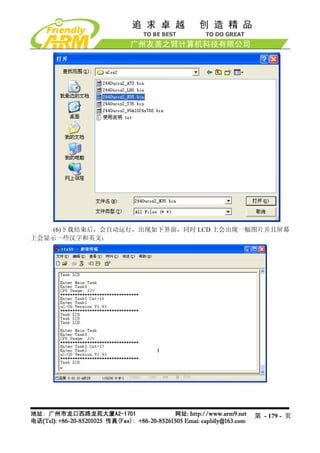
![(4)这时在超级终端的 BIOS 功能菜单中选择功能号[d],出现 USB 下载等待提示信息:
(5)点击 DNW 程序的“USB Port” “Transmit”,选择 NK.nb0 映象文件(在光盘的
imageswince5.0 目录下面),接着点“打开” ,这样就开始下载了。
第 - 185 - 页](https://image.slidesharecdn.com/mini2440-um-20090817-091005002637-phpapp02/85/Mini2440-Um-20090817-185-320.jpg)

![4.3.2 通过 USB 把 2440test 下载到内存运行
使用 USB 下载运行 2440test 程序不需要并口和 JTAG 板,借助 Supervivi 的“Download
& Run”功能就可以了,下面是详细的操作步骤:
(1)连接好开发板电源,串口线,USB 线,并设置开发板为 NOR Flash 启动系统,分
别打开串口超级终端和 DNW,上电启动开发板。
(2)保证 USB 驱动已经安装好(前面已经详细介绍了 USB 驱动的安装方法),这时可以
看到 DNW 的标题栏显示[USB:OK],如果没有安装好驱动会显示[USB:x],如图所示:
(3)点 DNW 菜单 Configuration,设置 USB 下载运行地址为 0x30000000
第 - 207 - 页](https://image.slidesharecdn.com/mini2440-um-20090817-091005002637-phpapp02/85/Mini2440-Um-20090817-207-320.jpg)
![(4)这时在超级终端的 BIOS 功能菜单中选择功能号[d],出现 USB 下载等待提示信息:
(5)点击 DNW 程序的“USB Port” “Transmit”
,如图选择刚刚编译出的映象文件(光
盘“images2440test”目录中有已经编译好的可执行文件),这样就开始下载了
第 - 208 - 页](https://image.slidesharecdn.com/mini2440-um-20090817-091005002637-phpapp02/85/Mini2440-Um-20090817-208-320.jpg)
![使用 Supervivi 的功能号[a]可以把 2440test.bin 可执行程序烧写到 Nand Flash 中运行,
步骤如下:
(1)连接好开发板电源,串口线,USB 线,并设置开发板为 NOR Flash 启动系统,分
别打开串口超级终端和 DNW,上电启动开发板。
(2)保证 USB 驱动已经安装好(前面已经详细介绍了 USB 驱动的安装方法),这时可以
看到 DNW 的标题栏显示[USB:OK],如果没有安装好驱动会显示[USB:x],如图所示:
(3)这时在超级终端的 BIOS 功能菜单中选择功能号[a],出现 USB 下载等待提示信息:
第 - 210 - 页](https://image.slidesharecdn.com/mini2440-um-20090817-091005002637-phpapp02/85/Mini2440-Um-20090817-210-320.jpg)
![编译完毕,在 D:workuCos2uCOS_2440_DataDebugRel 目录下会生成 2440ucos2.bin
可执行文件,如图。
4.5.2 把 uCos2 下载到内存运行
(1)连接好开发板电源,串口线,USB 线,并设置开发板为 Nor Flash 启动系统,分别
打开串口超级终端和 DNW,上电启动开发板。
(2)保证 USB 驱动已经安装好(前面已经详细介绍了 USB 驱动的安装方法),这时可以
看到 DNW 的标题栏显示[USB:OK],如果没有安装好驱动会显示[USB:x],如图所示:
第 - 214 - 页](https://image.slidesharecdn.com/mini2440-um-20090817-091005002637-phpapp02/85/Mini2440-Um-20090817-214-320.jpg)
![(3)点 DNW 菜单 Configuration,设置 USB 下载运行地址为 0x30000000
(4)这时在超级终端的 BIOS 功能菜单中选择功能号[d],出现 USB 下载等待提示信息:
第 - 215 - 页](https://image.slidesharecdn.com/mini2440-um-20090817-091005002637-phpapp02/85/Mini2440-Um-20090817-215-320.jpg)
把它烧写到 Nand Flash 中,步骤如下:
(1)连接好开发板电源,串口线,USB 线,并设置开发板为 Nor Flash 启动系统,分别
打开串口超级终端和 DNW,上电启动开发板。
(2)保证 USB 驱动已经安装好(前面已经详细介绍了 USB 驱动的安装方法),这时可以
看到 DNW 的标题栏显示[USB:OK],如果没有安装好驱动会显示[USB:x],如图所示:
第 - 217 - 页](https://image.slidesharecdn.com/mini2440-um-20090817-091005002637-phpapp02/85/Mini2440-Um-20090817-217-320.jpg)
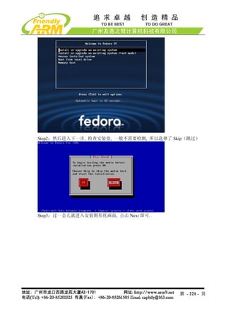
![(3)这时在超级终端的 BIOS 功能菜单中选择功能号[a],出现 USB 下载等待提示信息:
(4)点击 DNW 程序的“USB Port” “Transmit”,如图选择刚刚编译出的映象文件(光
第 - 218 - 页](https://image.slidesharecdn.com/mini2440-um-20090817-091005002637-phpapp02/85/Mini2440-Um-20090817-218-320.jpg)


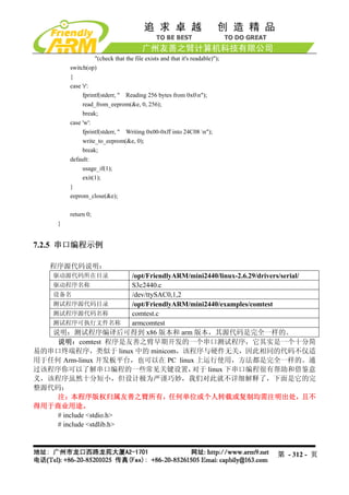
![7.2 嵌入式 Linux 程序开发入门
声明:以下 Linux 示例程序均为友善之臂原创,我们发现有的开发板厂商或者个人修
改了 copyright 说明,据为己有,虽然国内对这种抄袭行为基本没有法律约束,但我们对这种
无耻的盗窃行为予以鄙视,并敬告大家要尊重原厂家的辛苦劳动。
7.2.1 LED 测试程序
程序源代码说明:
驱动源代码所在目录 /opt/FriendlyARM/mini2440/linux-2.6.29/drivers/char
驱动程序名称 mini2440_leds.c
设备类型 misc
设备名 /dev/leds
测试程序源代码目录 /opt/FriendlyARM/mini2440/examples/leds
测试程序名称 led.c
测试程序可执行文件名称 led
说明:LED 驱动已经被编译到缺省内核中,因此不能再使用 insmod 方式加载。
测试程序清单:
#include <stdio.h>
#include <stdlib.h>
#include <unistd.h>
#include <sys/ioctl.h>
int main(int argc, char **argv)
{
int on;
int led_no;
int fd;
/* 检查 led 控制的两个参数,如果没有参数输入则退出。*/
if (argc != 3 || sscanf(argv[1], "%d", &led_no) != 1 || sscanf(argv[2],"%d", &on) != 1 ||
on < 0 || on > 1 || led_no < 0 || led_no > 3) {
fprintf(stderr, "Usage: leds led_no 0|1n");
exit(1);
}
/*打开/dev/leds 设备文件*/
fd = open("/dev/leds0", 0);
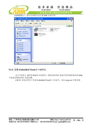
第 - 303 - 页](https://image.slidesharecdn.com/mini2440-um-20090817-091005002637-phpapp02/85/Mini2440-Um-20090817-303-320.jpg)
![#include <errno.h>
int main(void)
{
int buttons_fd;
char buttons[6] = {'0', '0', '0', '0', '0', '0'};
buttons_fd = open("/dev/buttons", 0);
if (buttons_fd < 0) {
perror("open device buttons");
exit(1);
}
for (;;) {
char current_buttons[6];
int count_of_changed_key;
int i;
if (read(buttons_fd, current_buttons, sizeof current_buttons) != sizeof current_buttons)
{
perror("read buttons:");
exit(1);
}
for (i = 0, count_of_changed_key = 0; i < sizeof buttons / sizeof buttons[0]; i++) {
if (buttons[i] != current_buttons[i]) {
buttons[i] = current_buttons[i];
printf("%skey %d is %s", count_of_changed_key? ", ": "", i+1, buttons[i] ==
'0' ? "up" : "down");
count_of_changed_key++;
}
}
if (count_of_changed_key) {
printf("n");
}
}
close(buttons_fd);
return 0;
}
第 - 305 - 页](https://image.slidesharecdn.com/mini2440-um-20090817-091005002637-phpapp02/85/Mini2440-Um-20090817-305-320.jpg)

![#include <stdio.h>
#include <fcntl.h>
#include <getopt.h>
#include <unistd.h>
#include <stdlib.h>
#include <errno.h>
#include <string.h>
#include <sys/types.h>
#include <sys/stat.h>
#include "24cXX.h"
#define usage_if(a) do { do_usage_if( a , __LINE__); } while(0);
void do_usage_if(int b, int line)
{
const static char *eeprog_usage =
"I2C-24C08(256 bytes) Read/Write Program, ONLY FOR TEST!n"
"FriendlyARM Computer Tech. 2009n";
if(!b)
return;
fprintf(stderr, "%sn[line %d]n", eeprog_usage, line);
exit(1);
}
#define die_if(a, msg) do { do_die_if( a , msg, __LINE__); } while(0);
void do_die_if(int b, char* msg, int line)
{
if(!b)
return;
fprintf(stderr, "Error at line %d: %sn", line, msg);
fprintf(stderr, " sysmsg: %sn", strerror(errno));
exit(1);
}
static int read_from_eeprom(struct eeprom *e, int addr, int size)
{
int ch, i;
for(i = 0; i < size; ++i, ++addr)
{
die_if((ch = eeprom_read_byte(e, addr)) < 0, "read error");
第 - 310 - 页](https://image.slidesharecdn.com/mini2440-um-20090817-091005002637-phpapp02/85/Mini2440-Um-20090817-310-320.jpg)
![if( (i % 16) == 0 )
printf("n %.4x| ", addr);
else if( (i % 8) == 0 )
printf(" ");
printf("%.2x ", ch);
fflush(stdout);
}
fprintf(stderr, "nn");
return 0;
}
static int write_to_eeprom(struct eeprom *e, int addr)
{
int i;
for(i=0, addr=0; i<256; i++, addr++)
{
if( (i % 16) == 0 )
printf("n %.4x| ", addr);
else if( (i % 8) == 0 )
printf(" ");
printf("%.2x ", i);
fflush(stdout);
die_if(eeprom_write_byte(e, addr, i), "write error");
}
fprintf(stderr, "nn");
return 0;
}
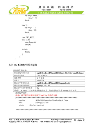
int main(int argc, char** argv)
{
struct eeprom e;
int op;
op = 0;
usage_if(argc != 2 || argv[1][0] != '-' || argv[1][2] != '0');
op = argv[1][1];
fprintf(stderr, "Open /dev/i2c/0 with 8bit moden");
die_if(eeprom_open("/dev/i2c/0", 0x50, EEPROM_TYPE_8BIT_ADDR, &e) < 0,
"unable to open eeprom device file "
第 - 311 - 页](https://image.slidesharecdn.com/mini2440-um-20090817-091005002637-phpapp02/85/Mini2440-Um-20090817-311-320.jpg)
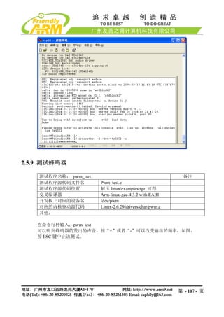
![fprintf(stderr, "press [ESC] 3 times to quitnn");
fprintf(stderr, "Usage: comtest [-d device] [-t tty] [-s speed] [-7] [-c] [-x] [-o] [-h]n");
fprintf(stderr, " -7 7 bitn");
fprintf(stderr, " -x hex moden");
fprintf(stderr, " -o output to stdout toon");
fprintf(stderr, " -c stdout output use colorn");
fprintf(stderr, " -h print this helpn");
exit(-1);
}
static inline void WaitFdWriteable(int Fd)
{
fd_set WriteSetFD;
FD_ZERO(&WriteSetFD);
FD_SET(Fd, &WriteSetFD);
if (select(Fd + 1, NULL, &WriteSetFD, NULL, NULL) < 0) {
Error(strerror(errno));
}
}
int main(int argc, char **argv)
{
int CommFd, TtyFd;
struct termios TtyAttr;
struct termios BackupTtyAttr;
int DeviceSpeed = B115200;
int TtySpeed = B115200;
int ByteBits = CS8;
const char *DeviceName = "/dev/ttyS0";
const char *TtyName = "/dev/tty";
int OutputHex = 0;
int OutputToStdout = 0;
int UseColor = 0;
opterr = 0;
for (;;) {
int c = getopt(argc, argv, "d:s:t:7xoch");
第 - 314 - 页](https://image.slidesharecdn.com/mini2440-um-20090817-091005002637-phpapp02/85/Mini2440-Um-20090817-314-320.jpg)
![if (c == -1)
break;
switch(c) {
case 'd':
DeviceName = optarg;
break;
case 't':
TtyName = optarg;
break;
case 's':
if (optarg[0] == 'd') {
DeviceSpeed = SerialSpeed(optarg + 1);
} else if (optarg[0] == 't') {
TtySpeed = SerialSpeed(optarg + 1);
} else
TtySpeed = DeviceSpeed = SerialSpeed(optarg);
break;
case 'o':
OutputToStdout = 1;
break;
case '7':
ByteBits = CS7;
break;
case 'x':
OutputHex = 1;
break;
case 'c':
UseColor = 1;
break;
case '?':
case 'h':
default:
PrintUsage();
}
}
if (optind != argc)
PrintUsage();
CommFd = open(DeviceName, O_RDWR, 0);
if (CommFd < 0)
Error("Unable to open device");
第 - 315 - 页](https://image.slidesharecdn.com/mini2440-um-20090817-091005002637-phpapp02/85/Mini2440-Um-20090817-315-320.jpg)
![if (fcntl(CommFd, F_SETFL, O_NONBLOCK) < 0)
Error("Unable set to NONBLOCK mode");
memset(&TtyAttr, 0, sizeof(struct termios));
TtyAttr.c_iflag = IGNPAR;
TtyAttr.c_cflag = DeviceSpeed | HUPCL | ByteBits | CREAD | CLOCAL;
TtyAttr.c_cc[VMIN] = 1;
if (tcsetattr(CommFd, TCSANOW, &TtyAttr) < 0)
Warning("Unable to set comm port");
TtyFd = open(TtyName, O_RDWR | O_NDELAY, 0);
if (TtyFd < 0)
Error("Unable to open tty");
TtyAttr.c_cflag = TtySpeed | HUPCL | ByteBits | CREAD | CLOCAL;
if (tcgetattr(TtyFd, &BackupTtyAttr) < 0)
Error("Unable to get tty");
if (tcsetattr(TtyFd, TCSANOW, &TtyAttr) < 0)
Error("Unable to set tty");
for (;;) {
unsigned char Char = 0;
fd_set ReadSetFD;
void OutputStdChar(FILE *File) {
char Buffer[10];
int Len = sprintf(Buffer, OutputHex ? "%.2X " : "%c", Char);
fwrite(Buffer, 1, Len, File);
}
FD_ZERO(&ReadSetFD);
FD_SET(CommFd, &ReadSetFD);
FD_SET( TtyFd, &ReadSetFD);
# define max(x,y) ( ((x) >= (y)) ? (x) : (y) )
if (select(max(CommFd, TtyFd) + 1, &ReadSetFD, NULL, NULL, NULL) < 0) {
第 - 316 - 页](https://image.slidesharecdn.com/mini2440-um-20090817-091005002637-phpapp02/85/Mini2440-Um-20090817-316-320.jpg)
![#include <sys/types.h>
#include <sys/socket.h>
#include <arpa/inet.h>
#include <stdio.h>
#define BUFLEN 255
int main(int argc, char **argv)
{
struct sockaddr_in peeraddr, /*存放谈话对方 IP 和端口的 socket 地址*/
localaddr;/*本端 socket 地址*/
int sockfd;
char recmsg[BUFLEN+1];
int socklen, n;
if(argc!=5){
printf("%s <dest IP address> <dest port> <source IP address> <source port>n",
argv[0]);
exit(0);
}
sockfd = socket(AF_INET, SOCK_DGRAM, 0);
if(sockfd<0){
printf("socket creating err in udptalkn");
exit(1);
}
socklen = sizeof(struct sockaddr_in);
memset(&peeraddr, 0, socklen);
peeraddr.sin_family=AF_INET;
peeraddr.sin_port=htons(atoi(argv[2]));
if(inet_pton(AF_INET, argv[1], &peeraddr.sin_addr)<=0){
printf("Wrong dest IP address!n");
exit(0);
}
memset(&localaddr, 0, socklen);
localaddr.sin_family=AF_INET;
if(inet_pton(AF_INET, argv[3], &localaddr.sin_addr)<=0){
printf("Wrong source IP address!n");
exit(0);
}
localaddr.sin_port=htons(atoi(argv[4]));
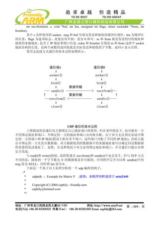
第 - 320 - 页](https://image.slidesharecdn.com/mini2440-um-20090817-091005002637-phpapp02/85/Mini2440-Um-20090817-320-320.jpg)
![if(bind(sockfd, &localaddr, socklen)<0){
printf("bind local address err in udptalk!n");
exit(2);
}
if(fgets(recmsg, BUFLEN, stdin) == NULL) exit(0);
if(sendto(sockfd, recmsg, strlen(recmsg), 0, &peeraddr, socklen)<0){
printf("sendto err in udptalk!n");
exit(3);
}
for(;;){
/*recv&send message loop*/
n = recvfrom(sockfd, recmsg, BUFLEN, 0, &peeraddr, &socklen);
if(n<0){
printf("recvfrom err in udptalk!n");
exit(4);
}else{
/*成功接收到数据报*/
recmsg[n]=0;
printf("peer:%s", recmsg);
}
if(fgets(recmsg, BUFLEN, stdin) == NULL) exit(0);
if(sendto(sockfd, recmsg, strlen(recmsg), 0, &peeraddr, socklen)<0){
printf("sendto err in udptalk!n");
exit(3);
}
}
}
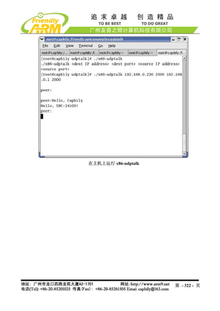
将 udptalk.c 编译好后就可以运行了,/opt/FriendlyARM/mini2440/examples/udptalk 目
录下的 Makefile 指定了两个编译目标可执行文件,一个用于在主机端的 x86-udptalk,一个是
用于开发板的 arm-udptalk, 运行 make 命令将把这两个程序一起编译出来。 可以把 arm-udptalk
使用上面介绍的方法下载到开发板中(预装的 Linux 不含该程序),假设主机的 IP 地址为
192.168.1.108,开发板的 IP 地址为 192.168.1.230。
在主机的终端上输入:
#./x86-udptalk 192.168.1.230 2000 192.168.1.108 2000
在开发板上的终端输入
#arm-udptalk 192.168.1.108 2000 192.168.1.230 2000
则运行结果分别如图所示:
第 - 321 - 页](https://image.slidesharecdn.com/mini2440-um-20090817-091005002637-phpapp02/85/Mini2440-Um-20090817-321-320.jpg)
![step.tv_sec = period;
step.tv_usec = (period - step.tv_sec) * 1000000L;
ret = select(led_control_pipe + 1, &rds, NULL, NULL, &step);
if (ret < 0) {
perror("select");
exit(1);
}
if (ret == 0) {
push_leds();
} else if (FD_ISSET(led_control_pipe, &rds)) {
static char buffer[200];
for (;;) {
char c;
int len = strlen(buffer);
if (len >= sizeof buffer - 1) {
memset(buffer, 0, sizeof buffer);
break;
}
if (read(led_control_pipe, &c, 1) != 1) {
break;
}
if (c == 'r') {
continue;
}
if (c == 'n') {
int tmp_type;
double tmp_period;
if (sscanf(buffer,"%d%lf", &tmp_type, &tmp_period) == 2) {
type = tmp_type;
period = tmp_period;
}
fprintf(stderr, "type is %d, period is %lfn", type, period);
memset(buffer, 0, sizeof buffer);
break;
}
buffer[len] = c;
}
}
}
第 - 329 - 页](https://image.slidesharecdn.com/mini2440-um-20090817-091005002637-phpapp02/85/Mini2440-Um-20090817-329-320.jpg)

![echo "Content-type: text/html; charset=gb2312"
echo
/bin/cat led-result.template
exit 0
7.2.10 基于 C++的 Hello,World
程序源代码说明:
测试程序源代码目录 /opt/FriendlyARM/mini2440/examples/c++
测试程序源代码名称 cplus.c++
测试程序可执行文件名称 cplus
说明:无
程序清单及注释:
程序清单:
#include <iostream>
#include <cstring>
using namespace std;
class String
{
private:
char *str;
public:
String(char *s)
{
int lenght=strlen(s);
str = new char[lenght+1];
strcpy(str, s);
}
~String()
{
cout << "Deleting str.n";
delete[] str;
}
void display()
{
cout << str <<endl;
}
第 - 331 - 页](https://image.slidesharecdn.com/mini2440-um-20090817-091005002637-phpapp02/85/Mini2440-Um-20090817-331-320.jpg)
![实际上,我们并不需要关心这些,写驱动时只要会使用他们就可以了,除非你所使用
的 CPU 体系平台尚没有被 Linux 所支持,因为大部分常见的嵌入式平台都已经有了很完善的
类似定义,你不需要自己去编写。
在下面的驱动程序清单中,你可以看到 s3c2410_gpio_cfgpin 被调用的情况。除此之
外,你还需要调用一些和设备驱动密切相关的基本函数,如注册设备 misc_register,填写驱动
函数结构 file_operations,以及像 Hello,Module 中那样的 module_init 和 module_exit 函数等。
有些函数并不是必须的,随着你对 Linux 驱动开发的进一步了解和阅读更多的代码,
你自然明白。下面是我们为 LED 编写的驱动代码清单,
驱动程序清单:
#include <linux/miscdevice.h>
#include <linux/delay.h>
#include <asm/irq.h>
#include <mach/regs-gpio.h>
#include <mach/hardware.h>
#include <linux/kernel.h>
#include <linux/module.h>
#include <linux/init.h>
#include <linux/mm.h>
#include <linux/fs.h>
#include <linux/types.h>
#include <linux/delay.h>
#include <linux/moduleparam.h>
#include <linux/slab.h>
#include <linux/errno.h>
#include <linux/ioctl.h>
#include <linux/cdev.h>
#include <linux/string.h>
#include <linux/list.h>
#include <linux/pci.h>
#include <asm/uaccess.h>
#include <asm/atomic.h>
#include <asm/unistd.h>
#define DEVICE_NAME "leds"
static unsigned long led_table [] = {
S3C2410_GPB5,
S3C2410_GPB6,
S3C2410_GPB7,
第 - 339 - 页](https://image.slidesharecdn.com/mini2440-um-20090817-091005002637-phpapp02/85/Mini2440-Um-20090817-339-320.jpg)
![S3C2410_GPB8,
};
static unsigned int led_cfg_table [] = {
S3C2410_GPB5_OUTP,
S3C2410_GPB6_OUTP,
S3C2410_GPB7_OUTP,
S3C2410_GPB8_OUTP,
};
static int sbc2440_leds_ioctl(
struct inode *inode,
struct file *file,
unsigned int cmd,
unsigned long arg)
{
switch(cmd) {
case 0:
case 1:
if (arg > 4) {
return -EINVAL;
}
s3c2410_gpio_setpin(led_table[arg], !cmd);
return 0;
default:
return -EINVAL;
}
}
static struct file_operations dev_fops = {
.owner = THIS_MODULE,
.ioctl = sbc2440_leds_ioctl,
};
static struct miscdevice misc = {
.minor = MISC_DYNAMIC_MINOR,
.name = DEVICE_NAME,
.fops = &dev_fops,
};
static int __init dev_init(void)
第 - 340 - 页](https://image.slidesharecdn.com/mini2440-um-20090817-091005002637-phpapp02/85/Mini2440-Um-20090817-340-320.jpg)
![{
int ret;
int i;
for (i = 0; i < 4; i++) {
s3c2410_gpio_cfgpin(led_table[i], led_cfg_table[i]);
s3c2410_gpio_setpin(led_table[i], 0);
}
ret = misc_register(&misc);
printk (DEVICE_NAME"tinitializedn");
return ret;
}
static void __exit dev_exit(void)
{
misc_deregister(&misc);
}
module_init(dev_init);
module_exit(dev_exit);
MODULE_LICENSE("GPL");
MODULE_AUTHOR("FriendlyARM Inc.");
7.4.2 按键驱动程序
程序源代码说明:
驱动源代码所在目录 /opt/FriendlyARM/mini2440/linux-2.6.29/drivers/char
驱动程序名称 mini2440_buttons.c
该驱动的主设备号 Misc 设备,设备号将自动生成
设备名 /dev/buttons
测试程序源代码目录 /opt/FriendlyARM/mini2440/examples/buttons
测试程序源代码名称 buttons_test.c
测试程序可执行文件名称 buttons
说明:按键驱动已经被编译到缺省内核中,因此不能再使用 insmod 方式加载。
开发板所用到的按键资源如下:
第 - 341 - 页](https://image.slidesharecdn.com/mini2440-um-20090817-091005002637-phpapp02/85/Mini2440-Um-20090817-341-320.jpg)
![按键 对应的 IO 寄存器名称 对应的中断
K1 GPG0 EINT8
K2 GPG3 EINT11
K3 GPG5 EINT13
K4 GPG6 EINT14
K5 GPG7 EINT15
K6 GPG11 EINT19
按键驱动源代码清单及注释:
#include <linux/module.h>
#include <linux/kernel.h>
#include <linux/fs.h>
#include <linux/init.h>
#include <linux/delay.h>
#include <linux/poll.h>
#include <linux/irq.h>
#include <asm/irq.h>
#include <linux/interrupt.h>
#include <asm/uaccess.h>
#include <mach/regs-gpio.h>
#include <mach/hardware.h>
#include <linux/platform_device.h>
#include <linux/cdev.h>
#include <linux/miscdevice.h>
#define DEVICE_NAME "buttons"
struct button_irq_desc {
int irq;
int pin;
int pin_setting;
int number;
char *name;
};
static struct button_irq_desc button_irqs [] = {
{IRQ_EINT8 , S3C2410_GPG0 , S3C2410_GPG0_EINT8 , 0, "KEY0"},
{IRQ_EINT11, S3C2410_GPG3 , S3C2410_GPG3_EINT11 , 1, "KEY1"},
{IRQ_EINT13, S3C2410_GPG5 , S3C2410_GPG5_EINT13 , 2, "KEY2"},
{IRQ_EINT15, S3C2410_GPG7 , S3C2410_GPG7_EINT15 , 3, "KEY3"},
{IRQ_EINT14, S3C2410_GPG6 , S3C2410_GPG6_EINT14 , 4, "KEY4"},
第 - 342 - 页](https://image.slidesharecdn.com/mini2440-um-20090817-091005002637-phpapp02/85/Mini2440-Um-20090817-342-320.jpg)
![{IRQ_EINT19, S3C2410_GPG11, S3C2410_GPG11_EINT19, 5, "KEY5"},
};
static volatile char key_values [] = {'0', '0', '0', '0', '0', '0'};
static DECLARE_WAIT_QUEUE_HEAD(button_waitq);
static volatile int ev_press = 0;
static irqreturn_t buttons_interrupt(int irq, void *dev_id)
{
struct button_irq_desc *button_irqs = (struct button_irq_desc *)dev_id;
int down;
// udelay(0);
down = !s3c2410_gpio_getpin(button_irqs->pin);
if (down != (key_values[button_irqs->number] & 1)) { // Changed
key_values[button_irqs->number] = '0' + down;
ev_press = 1;
wake_up_interruptible(&button_waitq);
}
return IRQ_RETVAL(IRQ_HANDLED);
}
static int s3c24xx_buttons_open(struct inode *inode, struct file *file)
{
int i;
int err;
for (i = 0; i < sizeof(button_irqs)/sizeof(button_irqs[0]); i++) {
err = request_irq(button_irqs[i].irq, buttons_interrupt,
IRQ_TYPE_EDGE_BOTH,
button_irqs[i].name, (void *)&button_irqs[i]);
if (err)
break;
第 - 343 - 页](https://image.slidesharecdn.com/mini2440-um-20090817-091005002637-phpapp02/85/Mini2440-Um-20090817-343-320.jpg)
![}
if (err) {
i--;
for (; i >= 0; i--) {
disable_irq(button_irqs[i].irq);
free_irq(button_irqs[i].irq, (void *)&button_irqs[i]);
}
return -EBUSY;
}
ev_press = 1;
return 0;
}
static int s3c24xx_buttons_close(struct inode *inode, struct file *file)
{
int i;
for (i = 0; i < sizeof(button_irqs)/sizeof(button_irqs[0]); i++) {
free_irq(button_irqs[i].irq, (void *)&button_irqs[i]);
}
return 0;
}
static int s3c24xx_buttons_read(struct file *filp, char __user *buff, size_t count, loff_t
*offp)
{
unsigned long err;
if (!ev_press) {
if (filp->f_flags & O_NONBLOCK)
return -EAGAIN;
else
wait_event_interruptible(button_waitq, ev_press);
}
第 - 344 - 页](https://image.slidesharecdn.com/mini2440-um-20090817-091005002637-phpapp02/85/Mini2440-Um-20090817-344-320.jpg)


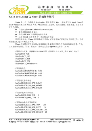
![关于更多的内核配置和更改用户可以自己摸索尝试,或者参考相关网上资料等,在此
不再叙述。
9.1.9 制作 WindowsCE 开机画面 StartLogo
在前面的章节,我们提到过:
WindowsCE 系统的启动过程有两种 Logo:BootLogo 和 StartLogo。其中 BootLogo 是
由 Nboot 加载显示的, 用户可以通过修改 Nboot 的源代码调整 BootLogo 的显示位置和背景色;
StartLogo 则 属 于 BSP 的 一 部 分 , 它 是 一 个 数 组 文 件 (StartLogo.c) , 位 于
“mini2440SrcKernelOal”目录,由该目录下的 init.c 文件实现加载显示,StartLogo.c 文件可
以通过本光盘中的 StartLogoMaker.exe 工具制作生成。
StartLogoMaker 由友善之臂开发的 Linux Logo 制作工具 LogoMaker(运行于 Fedora9)
移植而来,是一个“绿色软件” ,它不需要安装,直接复制到 WindowsXP/Vista 平台即可运行,
使用它可以把 bmp,jpg,png 等格式的图片转换为 mini2440 BSP 所需要的数组文件 StartLogo.c,
使用新生成的文件替换 BSP 中的同名文件,即可更换 WindowsCE 的启动画面,StartLogo.c
数组的头部内容如下:
// Automatic generated by StartLogo.exe from FriendlyARM Co., Ltd.
static const unsigned short StartLogoData[] = {
第 - 417 - 页](https://image.slidesharecdn.com/mini2440-um-20090817-091005002637-phpapp02/85/Mini2440-Um-20090817-417-320.jpg)
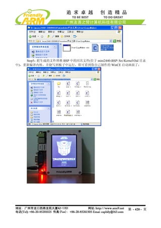
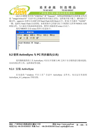
![4.6.2 把 NBOOT 烧写到 Nand Flash
(1)连接好开发板电源,串口线,USB 线,并设置拨动开关 S2 为 Nor Flash 启动系统,
分别打开串口超级终端和 DNW,上电启动开发板。
(2)保证 USB 驱动已经安装好(前面已经详细介绍了 USB 驱动的安装方法),这时可以
看到 DNW 的标题栏显示[USB:OK],如果没有安装好驱动会显示[USB:x],如图所示:
第 - 424 - 页](https://image.slidesharecdn.com/mini2440-um-20090817-091005002637-phpapp02/85/Mini2440-Um-20090817-424-320.jpg)
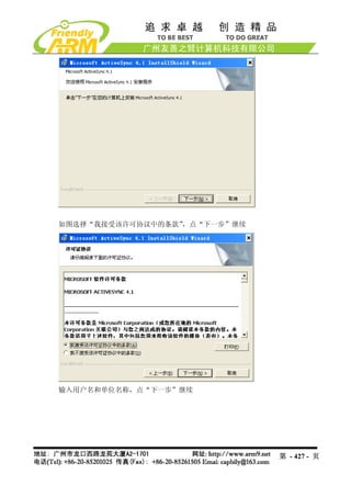
![(3)这时在超级终端的 BIOS 功能菜单中选择功能号[n],出现 USB 下载等待提示信息:
第 - 425 - 页](https://image.slidesharecdn.com/mini2440-um-20090817-091005002637-phpapp02/85/Mini2440-Um-20090817-425-320.jpg)

![LED_PowerDown
LED_PowerUp
LED_Read
LED_Seek
LED_Write
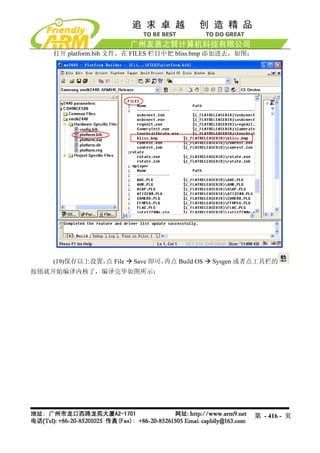
(5)在配置文件 platform.bib 中加入以下内容:
;leddriver
leddriver.dll $(_FLATRELEASEDIR)leddriver.dll NK SH
(6)在注册表文件 platform.reg 中加入以下内容:
[HKEY_LOCAL_MACHINEDriversBuiltInLEDdriver]
"Prefix"="LED"
"Dll"="LEDdriver.dll"
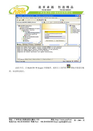
(7)重新编译内核, PB5 的主菜单 Build OS Sysgen 即可,
点 这样就可以生成包含以
上 LED 驱动的内核映象文件 NK.bin 和 NK.nb0 了。
9.5.4 编写并编译 LED 测试应用程序
示例文件在光盘中的位置:Windows CE5.0QQ2440test
示例文件所使用的编译器:eMbedded Visual C++ 4.0 + SP4 补丁 + QQ2440_SDK
SP4 补丁在光盘中的位置:Embedded VisualC++SPevc4sp4DISK1
QQ2440_SDK 安装文件在光盘中的位置:WindowsCE5.0SDK
要在应用程序中调用驱动程序,IO Control 是最常用的方法,它的一般流程如下:
在应用程序中:
HANDLE
leddriver=CreateFile(L"LED1:",GENERIC_READ|GENERIC_WRITE,0,NULL,OPEN_E
XISTING,0,NULL );
ReadFile(leddriver,………………..)
DeviceIoControl(leddriver,IO_CTL_LED_CLEAR,NULL,0,NULL,0,NULL,NULL);
在驱动程序中:
当 CreateFile 被调用时,调用 XXX_Open
当 ReadFile 被调用时,调用 XXX_Read
当 DeviceIoControl 被调用时,调用 XXX_IOContrl,根据 IO_CTL_XXX 的数值,决定
执行的操作。
在 LED 驱动中, 实现 10 个 IOControl 分支,处理 10 个命令请求, 对应点亮 1~4 号灯,,
点亮所有 LED,关闭 1~4 号等,关闭所有 LED 灯。
LED 测试程序的主要代码如下:
#define IO_CTL_LED_1_ON 0x01
#define IO_CTL_LED_2_ON 0x02
第 - 469 - 页](https://image.slidesharecdn.com/mini2440-um-20090817-091005002637-phpapp02/85/Mini2440-Um-20090817-469-320.jpg)

![附录 2 使用 BIOS 的命令行更新和烧写系统
说明:我们推荐使用前面介绍的功能菜单方式下载更新目标板系统,本小节内容仅供习
惯了命令行方式的老用户参考,不提供技术支持,也将不再继续更新本小节内容。
注意:新版 mini2440 已经采用 128M Nand Flash,本小节内容有可能不适用于新版
mini2440,因为此处介绍的方式很少使用,我们不再对此更新,仅保留供老用户参考。
1.1. 如何进入 BIOS 的命令行模式
1.1.1 从功能菜单进入命令行模式
如果 Supervivi 被烧写入 Nor Flash,并选择从 Nor Flash 启动,则系统开机启动时会进入
功能菜单模式,这时选择功能号[q]可以进入命令行模式,如图。
第 - 484 - 页](https://image.slidesharecdn.com/mini2440-um-20090817-091005002637-phpapp02/85/Mini2440-Um-20090817-484-320.jpg)