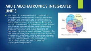
Mechatronics integrated unit is a system that
synergistically combines mechanical, electronic,
and software engineering to create intelligent,
automated products and processes. These units
incorporate sensors to gather environmental data,
actuators to perform actions, and controllers to
process information and make decisions, all
managed by programmed software. The goal of a
mechatronic integrated unit is to enhance product
functionality, efficiency, and automation, leading
to smart machines and systems like robots,
automated appliances, and advanced
automotive components.