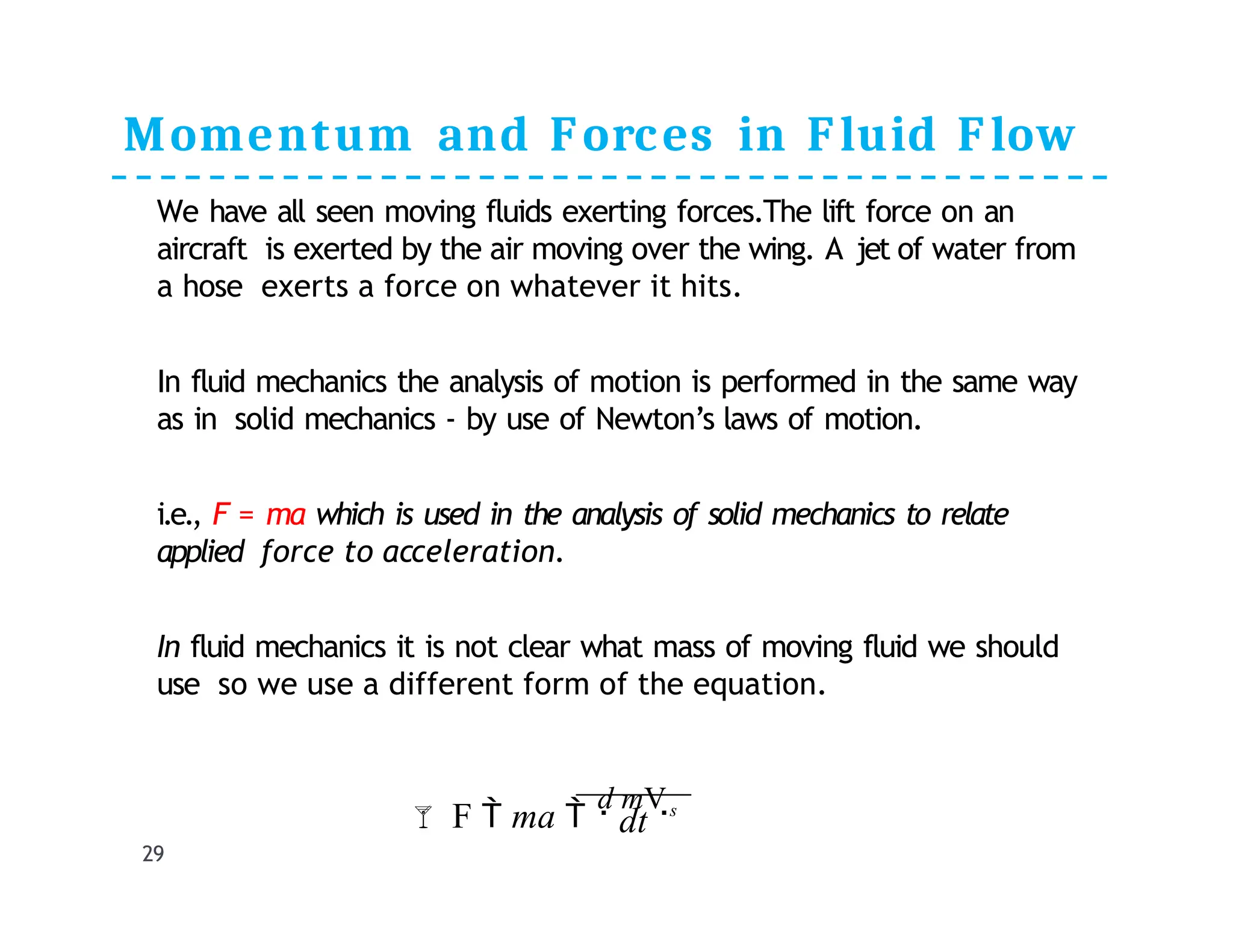
Fluid Dynamics:
(ii) Hydrodynamics: Different forms of energy in a flowing
liquid, head, Bernoulli's equation and its application, Energy
line and Hydraulic Gradient Line, and Energy Equation
Dr. Eng. Aldias Bahatmaka
Department of Mechanical Engineering
1
Fluid
Mechanics
Forms of Energy
(1). Kinetic Energy: Energy due to motion of body. A body
of mass, m, when moving with velocity, V, posses
kinetic energy,
(3). Pressure Energy: Energy due to pressure above datum,
most usually its pressure above atmospheric
PrE  h !!!
KE 
1
mV 2
2
PE  mgZ
m and V are mass and velocity of
body
2
(2). Potential Energy: Energy due to elevation of body above
an arbitrary datum
Z is elevation of body from
arbitrary datum
m is the mass of
body
Forms of Energy
3
(4). Internal Energy: It is the energy that is associated with
the molecular
, or internal state of matter; it may be stored
in many forms, including thermal, nuclear
, chemical and
electrostatic.
HEAD
Head: Energy per unit weight is called
head
Kinetic head: Kinetic energy per unit
weight
Potential head: Potential energy per unit
weigh
Pressure head: Pressure energy per unit
weight
V 2

2

Weight  2
2g
KE 
1
Kinetic head    mV  / mg

QWeight  mg
 mgZ / mg  Z
Weight
PE
Potential head

Weight

4
PrE

P
Pressure head

TOTAL HEAD
TOTAL HEAD
= Kinetic Head + Potential Head + Pressure Head
V 2
P
Total Head  H  Z  
 2g
2g
V 2 P

5
Z
Bernoulli’s Equation
It states that the sum of kinetic, potential and pressure
heads of a fluid particle is constant along a streamline
during steady flow when compressibility and frictional
effects are negligible.
i.e. , For an ideal fluid,Total head of fluid particle
remains constant during a steady-incompressible flow.
Or total head along a streamline is constant during steady
flow when compressibility and frictional effects are negligible.
H1  H 2
2 V 2
2
2
1
1
V 2
V 2
Total Head  Z 
P
P
Z   Z 
 1

2g
  constt
P
 2g

 2g
1
6
2
Pip
e
Derivation of Bernoulli’s Equation
7
Consider motion of flow
fluid particle in steady
flow field as shown in fig.
Applying Newton’s 2nd Law
in s- direction on a particle
moving along a streamline
give
W here F is resultant force in
s- direction, m is the mass
and as is the acceleration
along s-direction.
Fs  mas
Assumption:
Fluid is ideal and
incompressible Flow is
steady
Flow is along streamline
Velocity is uniform across the section
and is equal to mean velocity
Only gravity and pressure forces are
acting

dV

dsdV

dsdV
 V
dV
dt dsdt dtds
ds
as
Eq(1
)
Eq(2
)
Fig. Forces acting on particle along
streamline
Derivation of Bernoulli’s Equation
W =weight of fluid W  mg  dAdsg
Wsin()= component acting along s-
direction dA= Area of flow
ds=length between sections along pipe
Fs  PdA  P  dpdA W sin
Substituting values from Eq(2) and
Eq(3) to Eq(1)
Eq(3
)
PdA  P  dpdA W sin   mV
ds
dV
 dpdA  gdAds
dz
 dAdsV
dV
ds
ds
Cancelling dA and simplifying
sin 
dz
ds
2
1
 dp  gdz  VdV
Note that VdV 
1
dV 2
 dp  gdz  
dV 2
2
8
Eq(4
)
Eq(5
)
Fig. Forces acting on particle along
streamline
Derivation of Bernoulli’s Equation
9
Dividing eq (5) by

Integrating
Assuming incompressible
and steady flow
Dividing each equation
by g
1
2
2
dV 
0
 gdz 
dp


dp

  gdz  dV  
contt
 2 
1 2


2
 gz  V 
contt
2
P 1

 z   contt
2g
V 2

g
P
Hence Eq (9) for stead-
incompressible fluid assuming
no frictional losses can be
written as
Eq
(6)
Eq
(7)
Eq
(8)
Eq
(9)
1 2
2
1
1 2
Total Head  Total Head
P V 2
2
V 2
P 1
Z  
 Z
 

2g
 2g
Above Eq(10) is general form
of Bernoulli’s Equation
Eq
(10)
Energy Line and Hydraulic Grade line
10
Static
Pressure :
Dynamic
pressure :
 z   H
2g
V 2
P

P
Hydrostatic Pressure: gZ
Stagnation Pressure: Static pressure + dynamic
Pressure
V 2
/
2

contt
P  gz 

Pressure head  Elevation head  Velocity head  Total Head
Multiplying with unit
weight,γ,
V 2
2
 Pstag
V 2
P  
2
Energy Line and Hydraulic Grade line
11
Measurement of Heads
Piezometer: It
measures pressure
head ( P /  ).
Pitot tube: It measures
sum of pressure and
velocity heads i.e.,
V 2
P

 2g
W hat about measurement of elevation
head !!
Energy Line and Hydraulic Grade line
Energy line: It is line joining the total heads along a pipe
line.
HGL: It is line joining pressure head along a pipe line.
12
Energy Line and Hydraulic Grade line
13
Energy Equation for steady flow of any fluid
Let’s consider the energy
of system (Es) and energy
of control volume(Ecv)
defined within a stream
tube as shown in
figure.Therefore,
CV CV
 E
in
Eo
ut
Es 
ECV
CV
 E
in
s CV

Eout

E
Because the flow is
steady, conditions within
the control volume does
not change so
ECV  0
Hence
Eq(1
)
Eq(2
)
Figure: Forces/energies in fluid
flowing in streamt ube
14
Energy Equation for steady flow of any
fluid
15
out
CV CV
flowwork  shaftwork  heat transferred  E 
Ein
flowwork  shaftwork  heat transferred  Es
Now, let’s apply the first law of thermodynamics to the
fluid system which states ” For steady flow
, the external work
done on any system plus the thermal energy transferred into or out
of the system is equal to the change of energy of system”
External work done  heat transferred  change of energy
Flow work: When the pressure forces acting on the
boundaries move, in present case when p1A1 and p2A2 at the end
sections move through ∆s1 and ∆s2, external work is done. It is
referred to as flow work.
Q 1 A1s1  2 A2 s2
 m
 p p

p p
Flow work  p1 A1s1  p1
A1s1 
 2

Flow work  gm 1

2 2 2
2
1 1 1
1 2
1



 A s  
A s

Eq(5)
Steady
flow
Eq(3
)
Eq(4
)
Energy Equation for steady flow of any
fluid
16
Shaft work: Work done by machine, if any
, between section 1 and
2
m
time weight
weight energy
ds
h
t

dt





Shaft work  1
1 1
Shaft work  1 A1s1 hm 
gmhm
time  
A
Where, hm is the energy added to the flow by the machine
per unit weight of flowing fluid. Note: if the machine is pump,
which adds energy to the fluid, hm is positive and if the machine is
turbine, which remove energy from fluid, hm is -ve
Heat Transferred: The heat transferred from an external
source into the fluid system over time interval ∆t is
ds
QH
t
dt




 1
1 1
Heat transferred  1 A1s1 QH 
gmQH
Heat transferred  
A
Where, QH is the amount of energy put into the flow by the
external heat source per unit weight of flowing fluid. If the
heat flow is out of the fluid, the value QH is –ve and vice
versa
Eq(6
)
Eq(7
)
Energy Equation for steady flow of any
fluid
17
Change in Energy: For steady flow during time interval ∆t, the weight
of fluid entering the control volume at section 1 and leaving at section 2
are both equal to g∆m .Thus the energy (Potential+Kinetic+Internal)
carried by g∆m is;





2


E

2






 




E

1



Ei
n







1







Ei
n
2
2
2 2 2
2

 I t
 

A ds  z
2
2g
V 2
2
2
 z
dt

ds

2 2
 
A
1

gm
 z
1
1 1 1

1

1
2g
V 2
1
1
dt

ds

z  
1 1
 
A
2g
V 2

gm
z
  2
 I

2g
V 2
  2
 I

2g
V 2
  1
 I

2g
V 2
 I t
 
 A ds  z   1
 I

out
CV
out
CV
CV
CV
α is kinetic energy correction factor and ~
1
Eq(8
)
Eq(9
)
Energy Equation for steady flow of any
fluid
Substituting all values from Eqs. (5),(6), (7), (8), &
(9) in Eq(4) out
CV CV
flowwork  shaftwork  heat transferred  E 
Ein






1


 1
2

2
2
    gmQ 
gm z
gm
h
 p p 
 2g
V 2
2
2g
V 2
   I  gm z   1
 I 
H
m
gm 1

 1
 2  









 1
 I
1
2g
V 2
1
2
 I  z 

2
2g
V 2
2
2
 1 2


1
 p p 

H
m
  h  Q   z
 








 2
2
2
 2
2
1
1
1
 1
1  I

2g
V 2

p
 Q
 I  
h
2g
V 2

p
H
m
 z 


 z  

This is general form of energy equation, which applies to liquids, gases,
vapors and to ideal fluids as well as real fluids with friction, both incompressible
and compressible.The only restriction is that its for steady flow.
18
Eq(10
)
Energy Equation for steady flow of
incompressible fluid
For incompressible fluids
1   2  
Substituting in Eq(10), we
get
2 2 1
1
1 m H
2g

 p V 2

 h  Q   2
 z  2
  I  I 

2g

 p V 2

 z 



1


m

p
V 2

2 2 1 H
  2
 z  2
  I  I  Q
2g


p
V 2

 z  1
  h


1
2g


1


L
19
m   h
 p  z 
  h 


  


p
 z 
2g  2g

V 2

2
2
2
V 2

1
1
1




Eq(11
)
Q hL  I2  I1  QH
Where hL=(I2-I1)-QH= head loss. It equal to is gain in internal energy
minus any heat added by external source.
Hm is head removed/added by machines. It can also be referred to head
loss due to pipe fitting, contraction, expansion and bends etc in pipes.
Energy Equation for steady flow of
incompressible fluid
In the absence of machine, pipe fitting etc, Eq(11) can be written
as
When the head loss is caused only by wall or pipe friction,
hL becomes hf, where hf is head loss due to friction
p
20

p

  


2g  2g

V 2  V 2

 z1  1    2
 z2  2   hL
1




Eq(12
)
Power
21
Rate of work done is termed as power
Power=Energy/time
Power=(Energy/weight)(weight/time)
If H is total head=total energy/weight and γQ is
the weight flow rate
then above equation can be written as
Power=(H)(γQ)= γQH
In
BG:
In SI:
Power in
(Kilowatts)=(H)(γQ)/1000
1 horsepower=550ft.lb/s
Power in (horsepower)=(H)(γQ)/550
Reading Assignment
22
Kinetic energy correction factor
Limitation of Bernoulli’s Equation
Application of hydraulic grade line and
energy line
NUMERICALS

5.2.1
23
2
4

5.2.3

5.3.2
25
2
6

5.3.4

5.3.6
27

5.9.6
28
Momentum and Forces in Fluid Flow
We have all seen moving fluids exerting forces.The lift force on an
aircraft is exerted by the air moving over the wing. A jet of water from
a hose exerts a force on whatever it hits.
In fluid mechanics the analysis of motion is performed in the same way
as in solid mechanics - by use of Newton’s laws of motion.
i.e., F = ma which is used in the analysis of solid mechanics to relate
applied force to acceleration.
In fluid mechanics it is not clear what mass of moving fluid we should
use so we use a different form of the equation.
dt
29
 F  ma 
d mVs
Momentum and Forces in Fluid Flow
30
 Fdt  d mVs
It is also termed as impulse momentum
principle
Newton’s 2nd Law can be written:
The Rate of change of momentum of a body is equal to the resultant force
acting on the body, and takes place in the direction of the force.
 F 
d mVs
dt
 F  Sum of all external forces on a body of fluid or system s
mV  Momentum of fluid body in direction s
The symbols F and V represent vectors and so the change in momentum
must be in the same direction as force.
Impact of a J et on a Plane
31
Impact of a J et on a Plane
32
Thank you
Questions….
Feel free to
contact
33

Materi Tentang Sebuah Fluid Mechanics.pptx

  • 1.
    Fluid Dynamics: (ii) Hydrodynamics:Different forms of energy in a flowing liquid, head, Bernoulli's equation and its application, Energy line and Hydraulic Gradient Line, and Energy Equation Dr. Eng. Aldias Bahatmaka Department of Mechanical Engineering 1 Fluid Mechanics
  • 2.
    Forms of Energy (1).Kinetic Energy: Energy due to motion of body. A body of mass, m, when moving with velocity, V, posses kinetic energy, (3). Pressure Energy: Energy due to pressure above datum, most usually its pressure above atmospheric PrE  h !!! KE  1 mV 2 2 PE  mgZ m and V are mass and velocity of body 2 (2). Potential Energy: Energy due to elevation of body above an arbitrary datum Z is elevation of body from arbitrary datum m is the mass of body
  • 3.
    Forms of Energy 3 (4).Internal Energy: It is the energy that is associated with the molecular , or internal state of matter; it may be stored in many forms, including thermal, nuclear , chemical and electrostatic.
  • 4.
    HEAD Head: Energy perunit weight is called head Kinetic head: Kinetic energy per unit weight Potential head: Potential energy per unit weigh Pressure head: Pressure energy per unit weight V 2  2  Weight  2 2g KE  1 Kinetic head    mV  / mg  QWeight  mg  mgZ / mg  Z Weight PE Potential head  Weight  4 PrE  P Pressure head 
  • 5.
    TOTAL HEAD TOTAL HEAD =Kinetic Head + Potential Head + Pressure Head V 2 P Total Head  H  Z    2g 2g V 2 P  5 Z
  • 6.
    Bernoulli’s Equation It statesthat the sum of kinetic, potential and pressure heads of a fluid particle is constant along a streamline during steady flow when compressibility and frictional effects are negligible. i.e. , For an ideal fluid,Total head of fluid particle remains constant during a steady-incompressible flow. Or total head along a streamline is constant during steady flow when compressibility and frictional effects are negligible. H1  H 2 2 V 2 2 2 1 1 V 2 V 2 Total Head  Z  P P Z   Z   1  2g   constt P  2g   2g 1 6 2 Pip e
  • 7.
    Derivation of Bernoulli’sEquation 7 Consider motion of flow fluid particle in steady flow field as shown in fig. Applying Newton’s 2nd Law in s- direction on a particle moving along a streamline give W here F is resultant force in s- direction, m is the mass and as is the acceleration along s-direction. Fs  mas Assumption: Fluid is ideal and incompressible Flow is steady Flow is along streamline Velocity is uniform across the section and is equal to mean velocity Only gravity and pressure forces are acting  dV  dsdV  dsdV  V dV dt dsdt dtds ds as Eq(1 ) Eq(2 ) Fig. Forces acting on particle along streamline
  • 8.
    Derivation of Bernoulli’sEquation W =weight of fluid W  mg  dAdsg Wsin()= component acting along s- direction dA= Area of flow ds=length between sections along pipe Fs  PdA  P  dpdA W sin Substituting values from Eq(2) and Eq(3) to Eq(1) Eq(3 ) PdA  P  dpdA W sin   mV ds dV  dpdA  gdAds dz  dAdsV dV ds ds Cancelling dA and simplifying sin  dz ds 2 1  dp  gdz  VdV Note that VdV  1 dV 2  dp  gdz   dV 2 2 8 Eq(4 ) Eq(5 ) Fig. Forces acting on particle along streamline
  • 9.
    Derivation of Bernoulli’sEquation 9 Dividing eq (5) by  Integrating Assuming incompressible and steady flow Dividing each equation by g 1 2 2 dV  0  gdz  dp   dp    gdz  dV   contt  2  1 2   2  gz  V  contt 2 P 1   z   contt 2g V 2  g P Hence Eq (9) for stead- incompressible fluid assuming no frictional losses can be written as Eq (6) Eq (7) Eq (8) Eq (9) 1 2 2 1 1 2 Total Head  Total Head P V 2 2 V 2 P 1 Z    Z    2g  2g Above Eq(10) is general form of Bernoulli’s Equation Eq (10)
  • 10.
    Energy Line andHydraulic Grade line 10 Static Pressure : Dynamic pressure :  z   H 2g V 2 P  P Hydrostatic Pressure: gZ Stagnation Pressure: Static pressure + dynamic Pressure V 2 / 2  contt P  gz   Pressure head  Elevation head  Velocity head  Total Head Multiplying with unit weight,γ, V 2 2  Pstag V 2 P   2
  • 11.
    Energy Line andHydraulic Grade line 11 Measurement of Heads Piezometer: It measures pressure head ( P /  ). Pitot tube: It measures sum of pressure and velocity heads i.e., V 2 P   2g W hat about measurement of elevation head !!
  • 12.
    Energy Line andHydraulic Grade line Energy line: It is line joining the total heads along a pipe line. HGL: It is line joining pressure head along a pipe line. 12
  • 13.
    Energy Line andHydraulic Grade line 13
  • 14.
    Energy Equation forsteady flow of any fluid Let’s consider the energy of system (Es) and energy of control volume(Ecv) defined within a stream tube as shown in figure.Therefore, CV CV  E in Eo ut Es  ECV CV  E in s CV  Eout  E Because the flow is steady, conditions within the control volume does not change so ECV  0 Hence Eq(1 ) Eq(2 ) Figure: Forces/energies in fluid flowing in streamt ube 14
  • 15.
    Energy Equation forsteady flow of any fluid 15 out CV CV flowwork  shaftwork  heat transferred  E  Ein flowwork  shaftwork  heat transferred  Es Now, let’s apply the first law of thermodynamics to the fluid system which states ” For steady flow , the external work done on any system plus the thermal energy transferred into or out of the system is equal to the change of energy of system” External work done  heat transferred  change of energy Flow work: When the pressure forces acting on the boundaries move, in present case when p1A1 and p2A2 at the end sections move through ∆s1 and ∆s2, external work is done. It is referred to as flow work. Q 1 A1s1  2 A2 s2  m  p p  p p Flow work  p1 A1s1  p1 A1s1   2  Flow work  gm 1  2 2 2 2 1 1 1 1 2 1     A s   A s  Eq(5) Steady flow Eq(3 ) Eq(4 )
  • 16.
    Energy Equation forsteady flow of any fluid 16 Shaft work: Work done by machine, if any , between section 1 and 2 m time weight weight energy ds h t  dt      Shaft work  1 1 1 Shaft work  1 A1s1 hm  gmhm time   A Where, hm is the energy added to the flow by the machine per unit weight of flowing fluid. Note: if the machine is pump, which adds energy to the fluid, hm is positive and if the machine is turbine, which remove energy from fluid, hm is -ve Heat Transferred: The heat transferred from an external source into the fluid system over time interval ∆t is ds QH t dt      1 1 1 Heat transferred  1 A1s1 QH  gmQH Heat transferred   A Where, QH is the amount of energy put into the flow by the external heat source per unit weight of flowing fluid. If the heat flow is out of the fluid, the value QH is –ve and vice versa Eq(6 ) Eq(7 )
  • 17.
    Energy Equation forsteady flow of any fluid 17 Change in Energy: For steady flow during time interval ∆t, the weight of fluid entering the control volume at section 1 and leaving at section 2 are both equal to g∆m .Thus the energy (Potential+Kinetic+Internal) carried by g∆m is;      2   E  2             E  1    Ei n        1        Ei n 2 2 2 2 2 2   I t    A ds  z 2 2g V 2 2 2  z dt  ds  2 2   A 1  gm  z 1 1 1 1  1  1 2g V 2 1 1 dt  ds  z   1 1   A 2g V 2  gm z   2  I  2g V 2   2  I  2g V 2   1  I  2g V 2  I t    A ds  z   1  I  out CV out CV CV CV α is kinetic energy correction factor and ~ 1 Eq(8 ) Eq(9 )
  • 18.
    Energy Equation forsteady flow of any fluid Substituting all values from Eqs. (5),(6), (7), (8), & (9) in Eq(4) out CV CV flowwork  shaftwork  heat transferred  E  Ein       1    1 2  2 2     gmQ  gm z gm h  p p   2g V 2 2 2g V 2    I  gm z   1  I  H m gm 1   1  2             1  I 1 2g V 2 1 2  I  z   2 2g V 2 2 2  1 2   1  p p   H m   h  Q   z            2 2 2  2 2 1 1 1  1 1  I  2g V 2  p  Q  I   h 2g V 2  p H m  z     z    This is general form of energy equation, which applies to liquids, gases, vapors and to ideal fluids as well as real fluids with friction, both incompressible and compressible.The only restriction is that its for steady flow. 18 Eq(10 )
  • 19.
    Energy Equation forsteady flow of incompressible fluid For incompressible fluids 1   2   Substituting in Eq(10), we get 2 2 1 1 1 m H 2g   p V 2   h  Q   2  z  2   I  I   2g   p V 2   z     1   m  p V 2  2 2 1 H   2  z  2   I  I  Q 2g   p V 2   z  1   h   1 2g   1   L 19 m   h  p  z    h         p  z  2g  2g  V 2  2 2 2 V 2  1 1 1     Eq(11 ) Q hL  I2  I1  QH Where hL=(I2-I1)-QH= head loss. It equal to is gain in internal energy minus any heat added by external source. Hm is head removed/added by machines. It can also be referred to head loss due to pipe fitting, contraction, expansion and bends etc in pipes.
  • 20.
    Energy Equation forsteady flow of incompressible fluid In the absence of machine, pipe fitting etc, Eq(11) can be written as When the head loss is caused only by wall or pipe friction, hL becomes hf, where hf is head loss due to friction p 20  p       2g  2g  V 2  V 2   z1  1    2  z2  2   hL 1     Eq(12 )
  • 21.
    Power 21 Rate of workdone is termed as power Power=Energy/time Power=(Energy/weight)(weight/time) If H is total head=total energy/weight and γQ is the weight flow rate then above equation can be written as Power=(H)(γQ)= γQH In BG: In SI: Power in (Kilowatts)=(H)(γQ)/1000 1 horsepower=550ft.lb/s Power in (horsepower)=(H)(γQ)/550
  • 22.
    Reading Assignment 22 Kinetic energycorrection factor Limitation of Bernoulli’s Equation Application of hydraulic grade line and energy line
  • 23.
  • 24.
  • 25.
  • 26.
  • 27.
  • 28.
  • 29.
    Momentum and Forcesin Fluid Flow We have all seen moving fluids exerting forces.The lift force on an aircraft is exerted by the air moving over the wing. A jet of water from a hose exerts a force on whatever it hits. In fluid mechanics the analysis of motion is performed in the same way as in solid mechanics - by use of Newton’s laws of motion. i.e., F = ma which is used in the analysis of solid mechanics to relate applied force to acceleration. In fluid mechanics it is not clear what mass of moving fluid we should use so we use a different form of the equation. dt 29  F  ma  d mVs
  • 30.
    Momentum and Forcesin Fluid Flow 30  Fdt  d mVs It is also termed as impulse momentum principle Newton’s 2nd Law can be written: The Rate of change of momentum of a body is equal to the resultant force acting on the body, and takes place in the direction of the force.  F  d mVs dt  F  Sum of all external forces on a body of fluid or system s mV  Momentum of fluid body in direction s The symbols F and V represent vectors and so the change in momentum must be in the same direction as force.
  • 31.
    Impact of aJ et on a Plane 31
  • 32.
    Impact of aJ et on a Plane 32
  • 33.