Download as PDF, PPTX
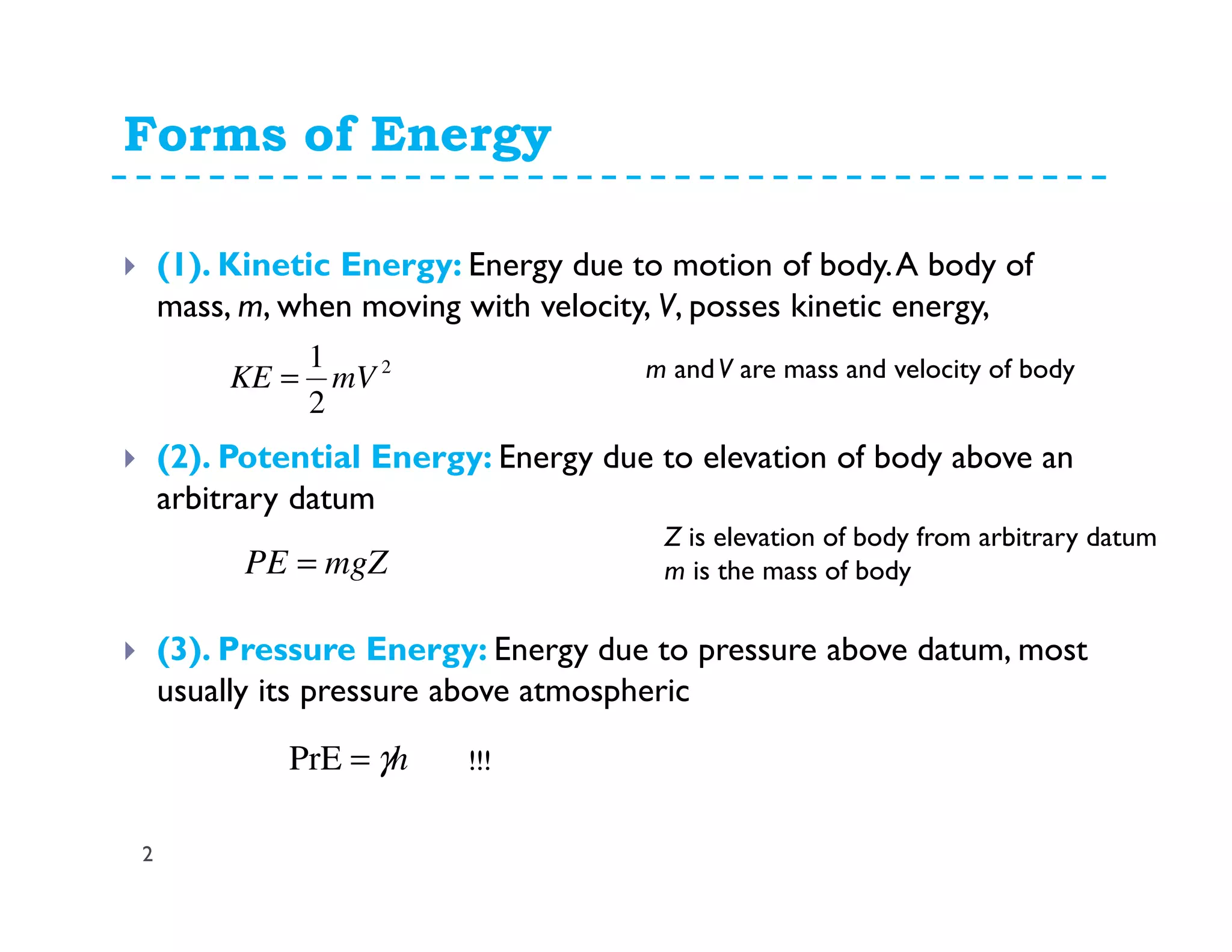
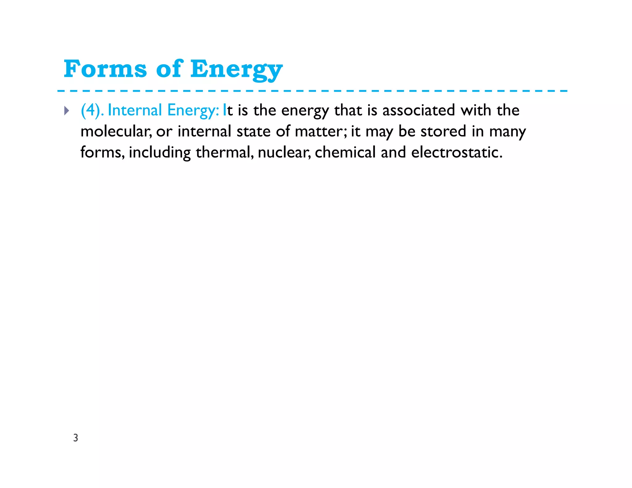
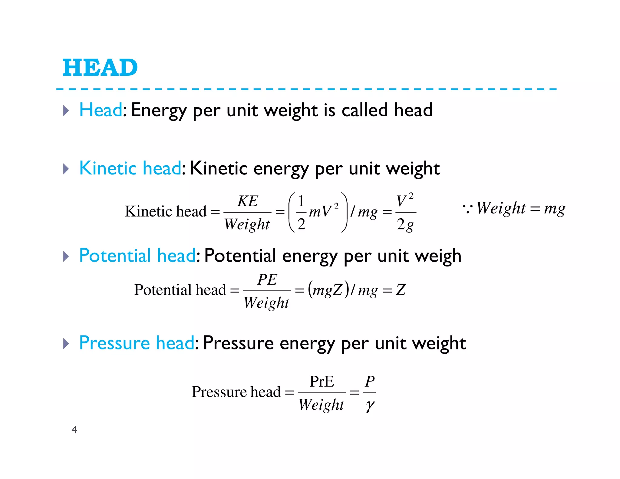
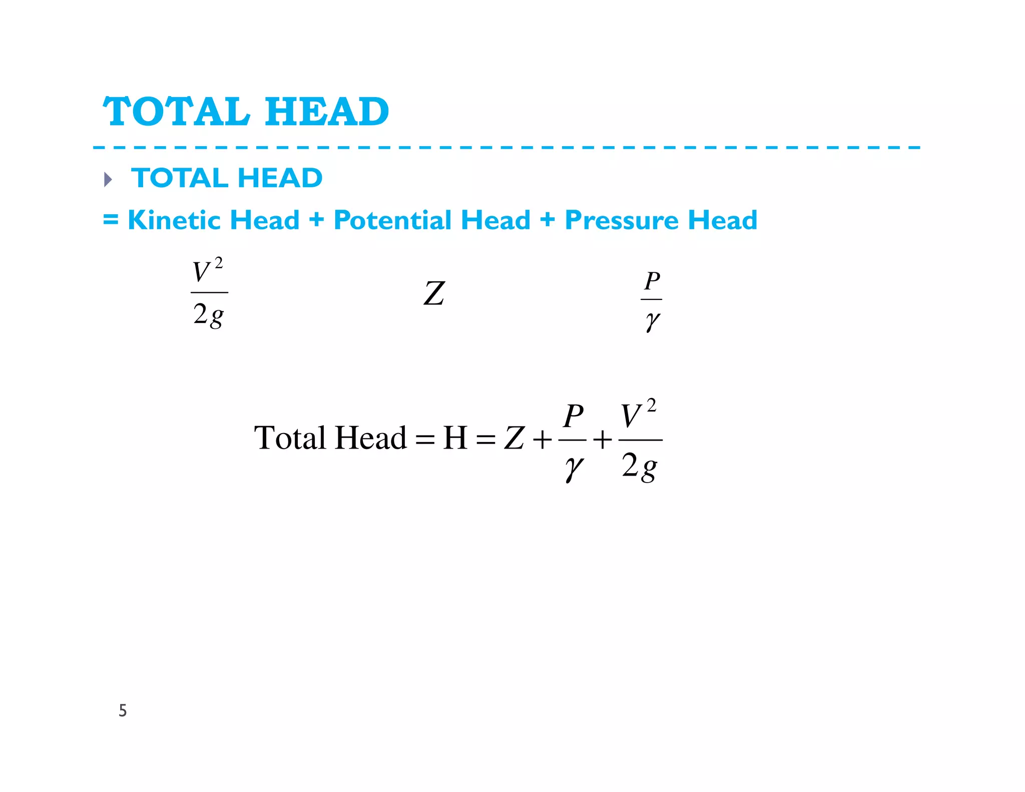
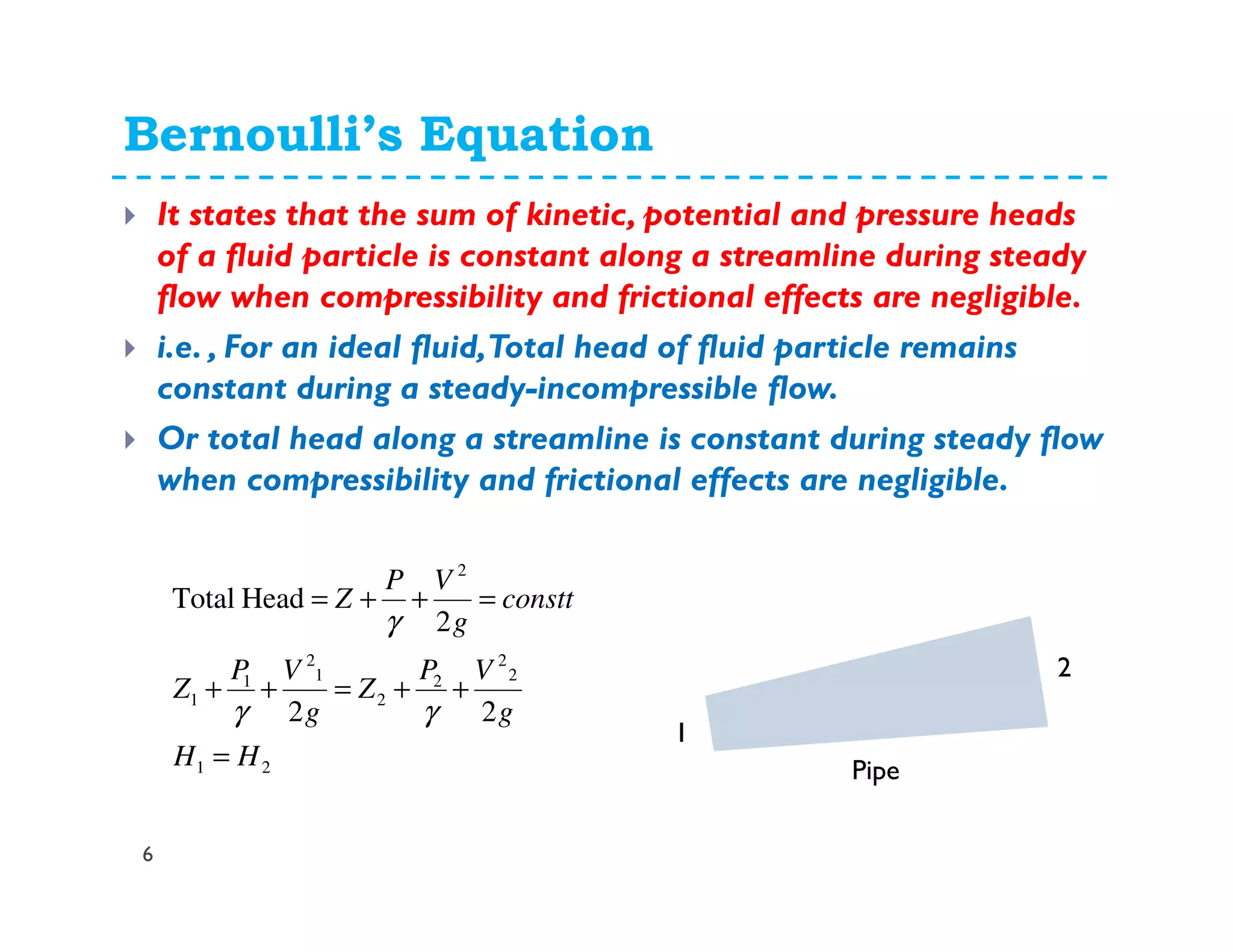
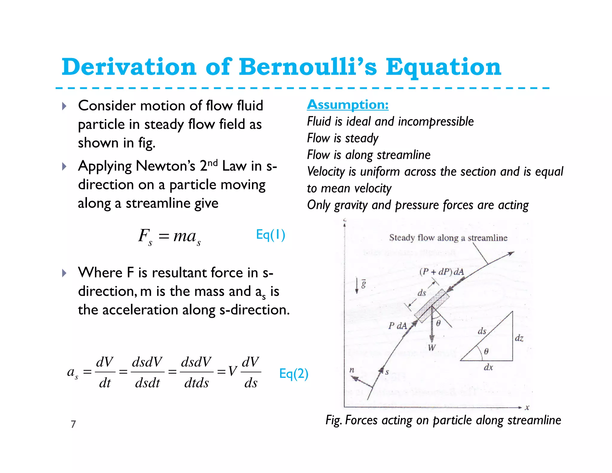
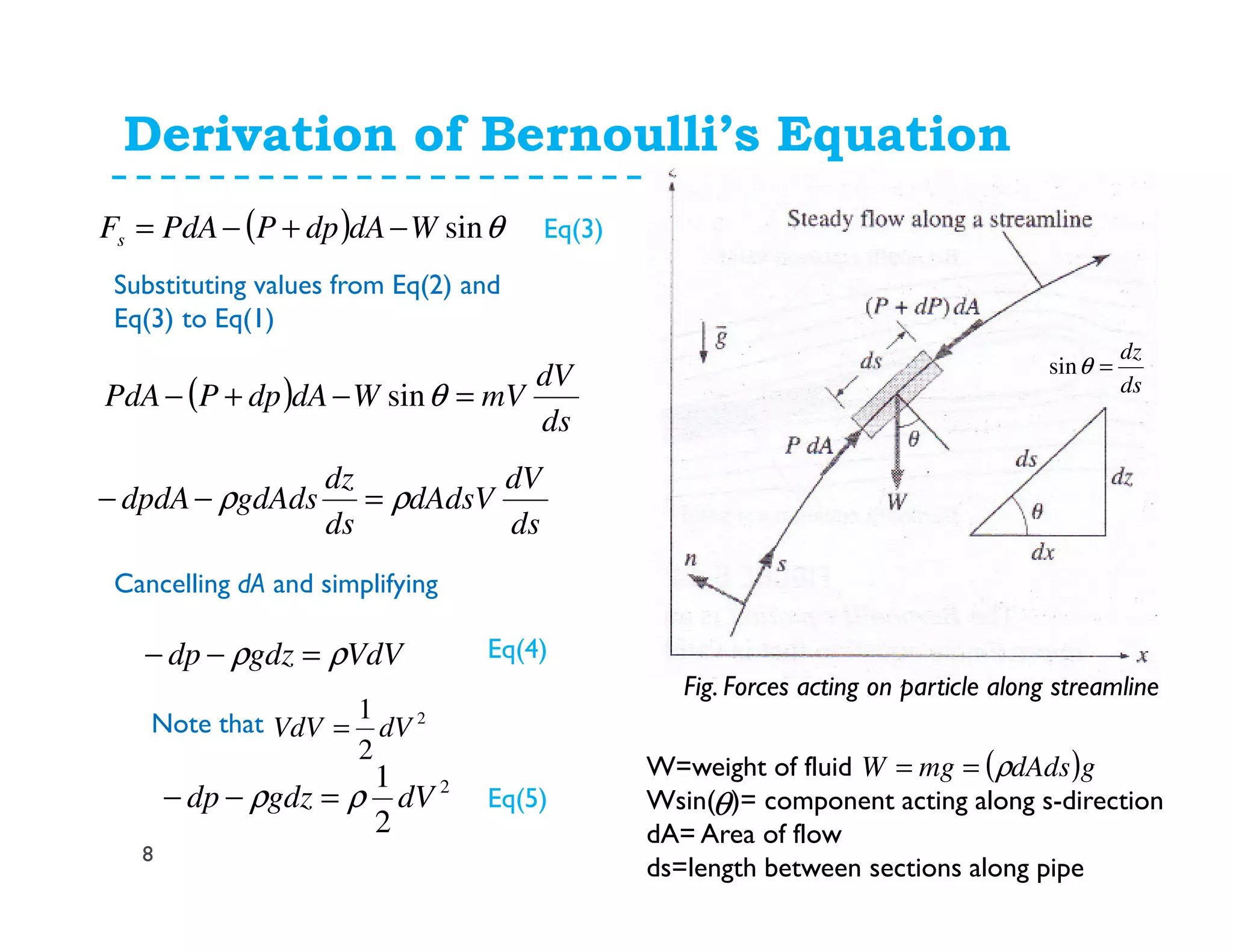
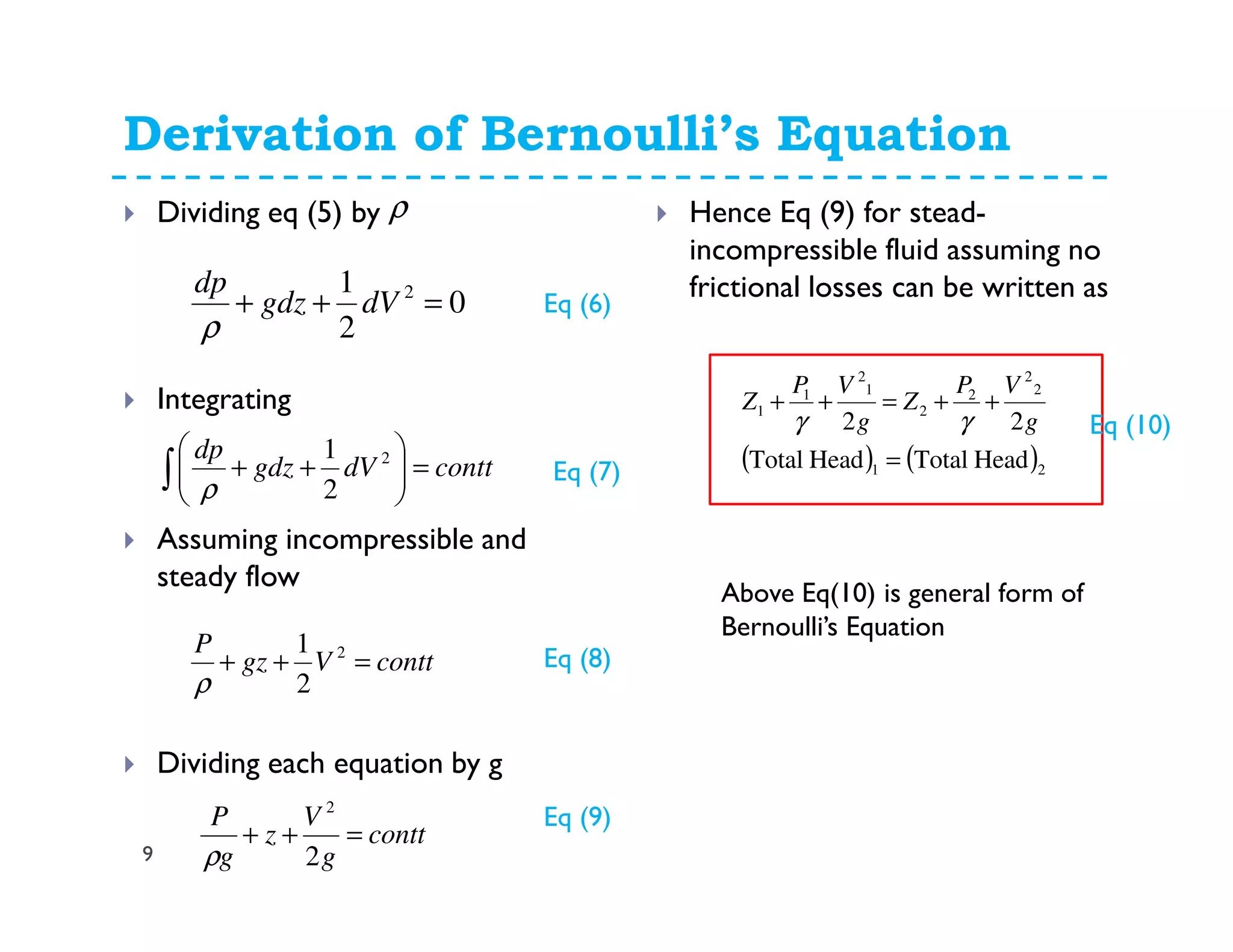
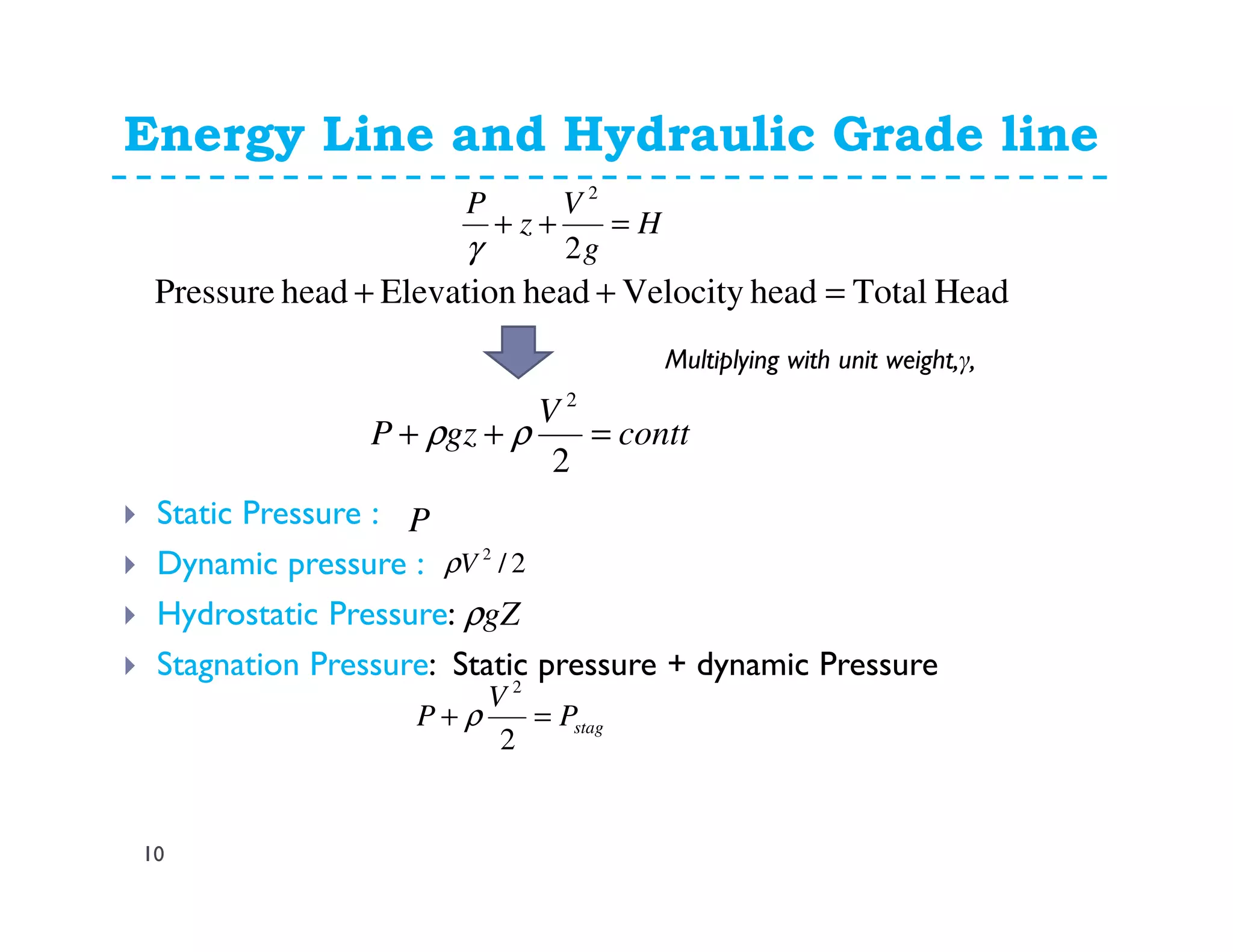
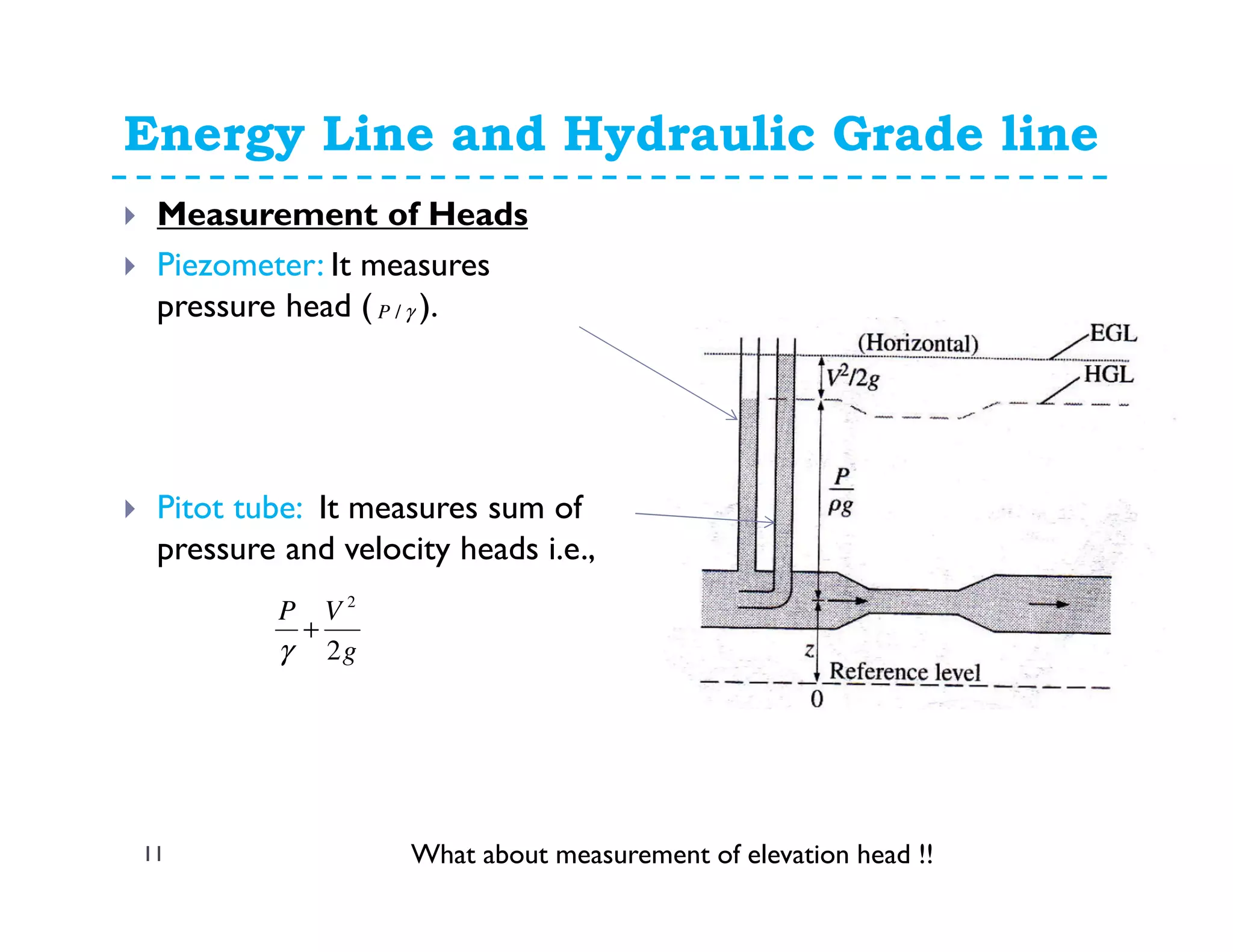
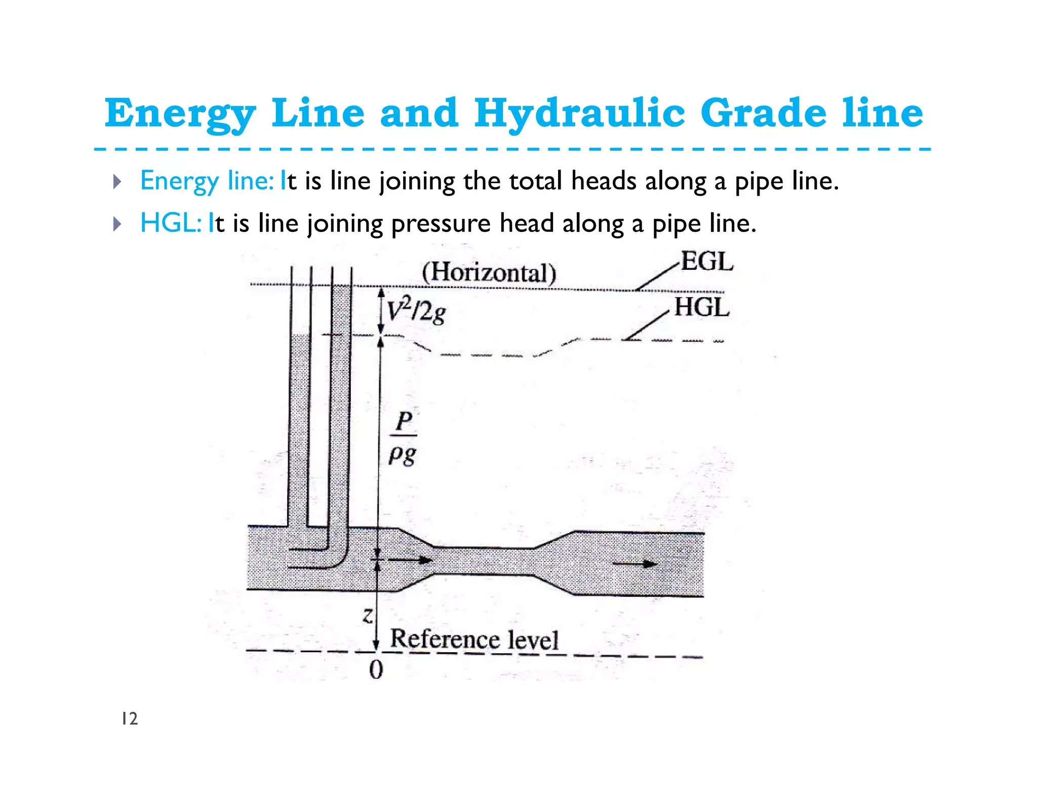
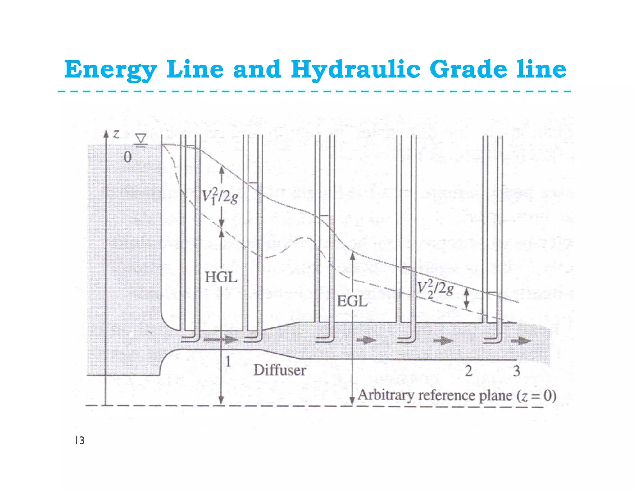
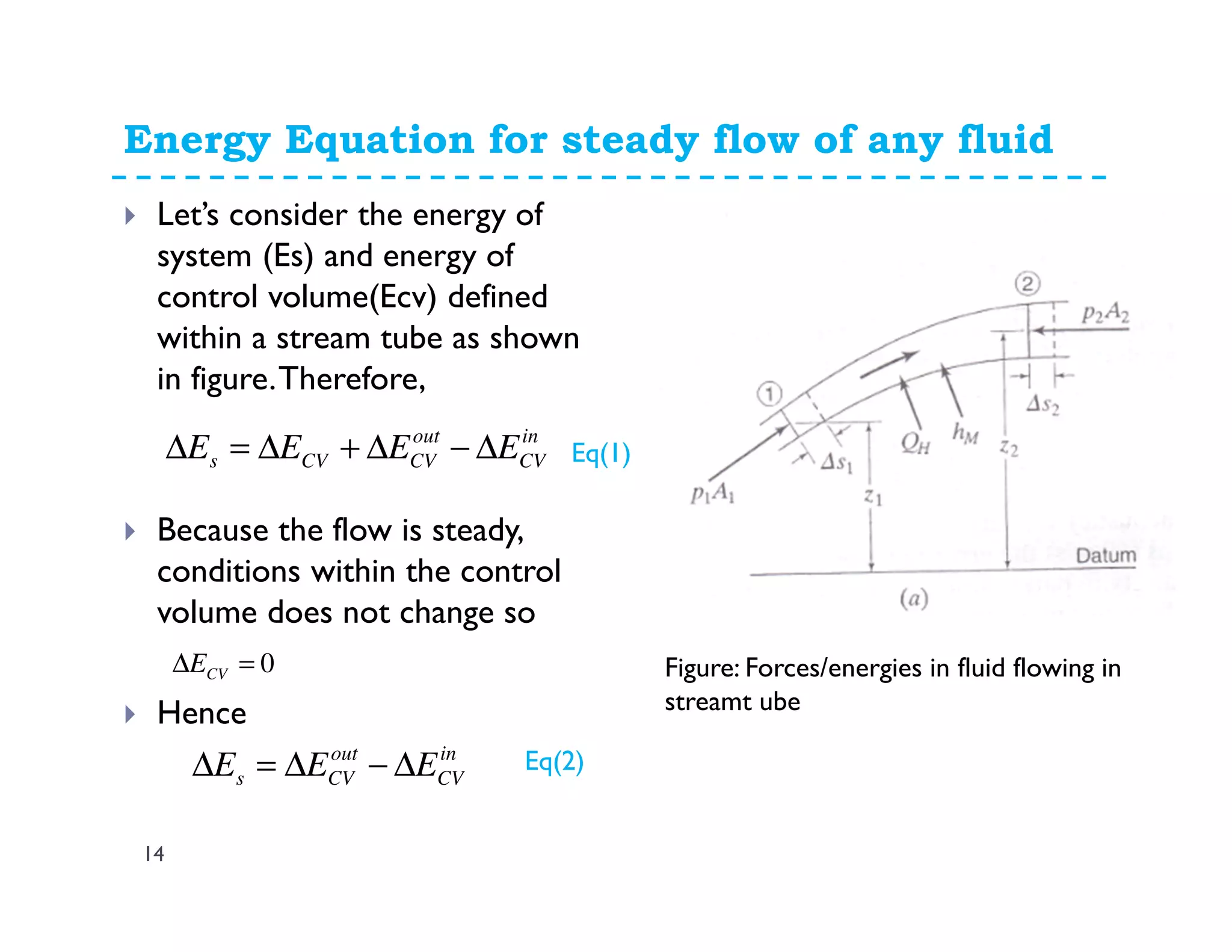
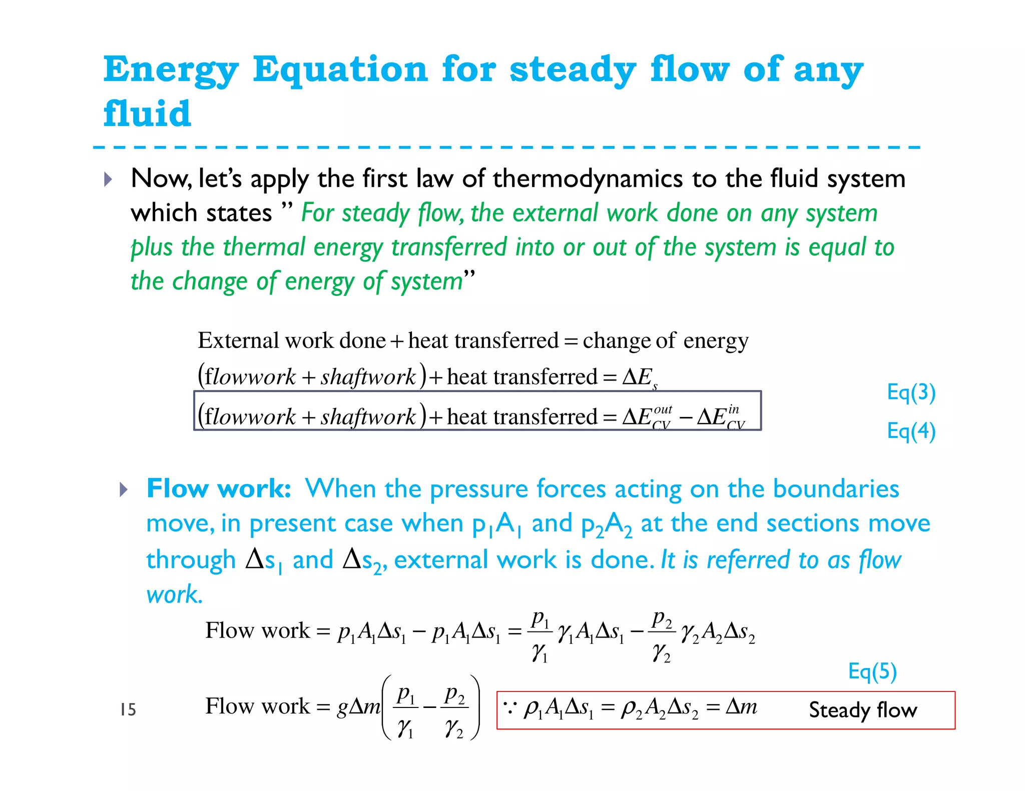
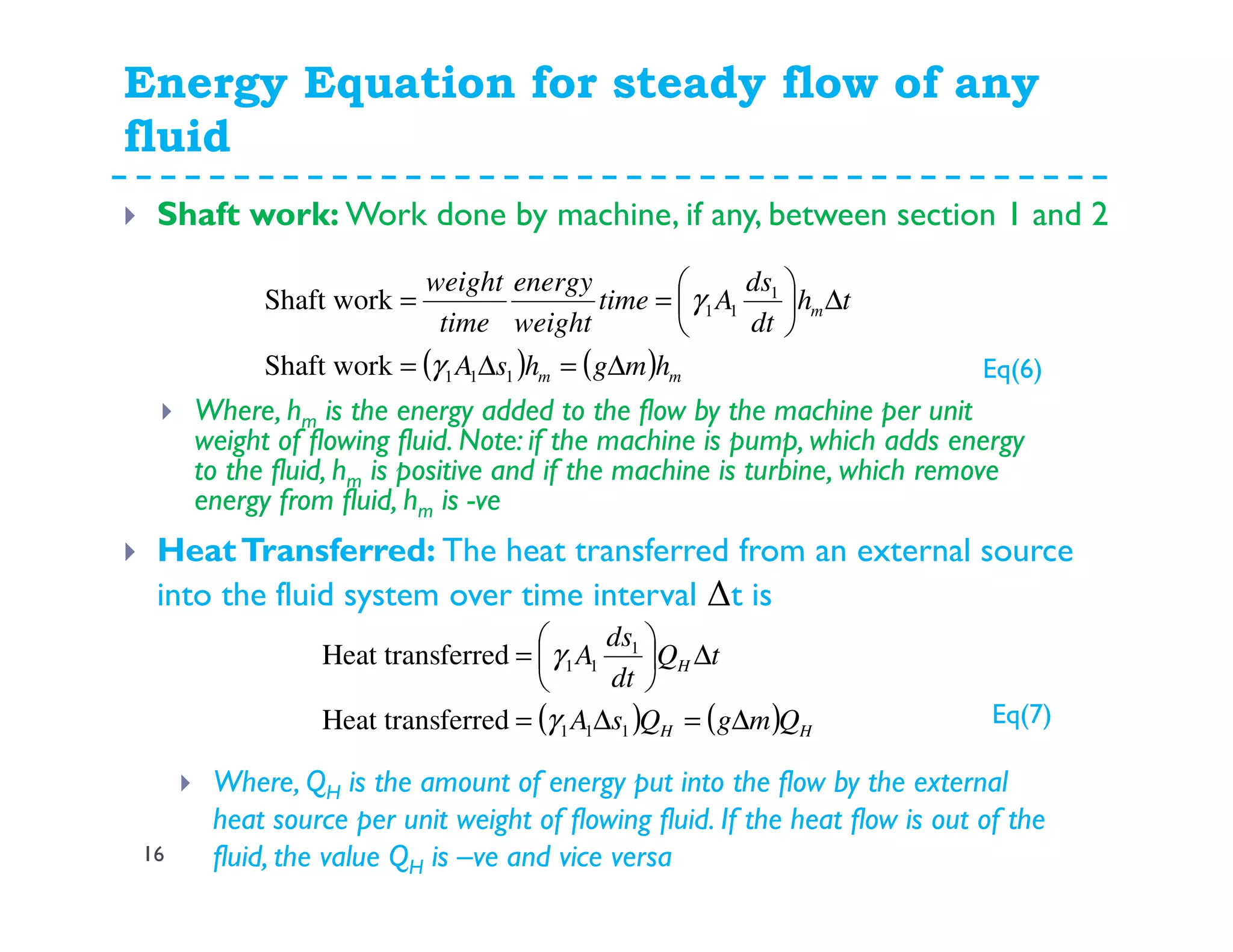

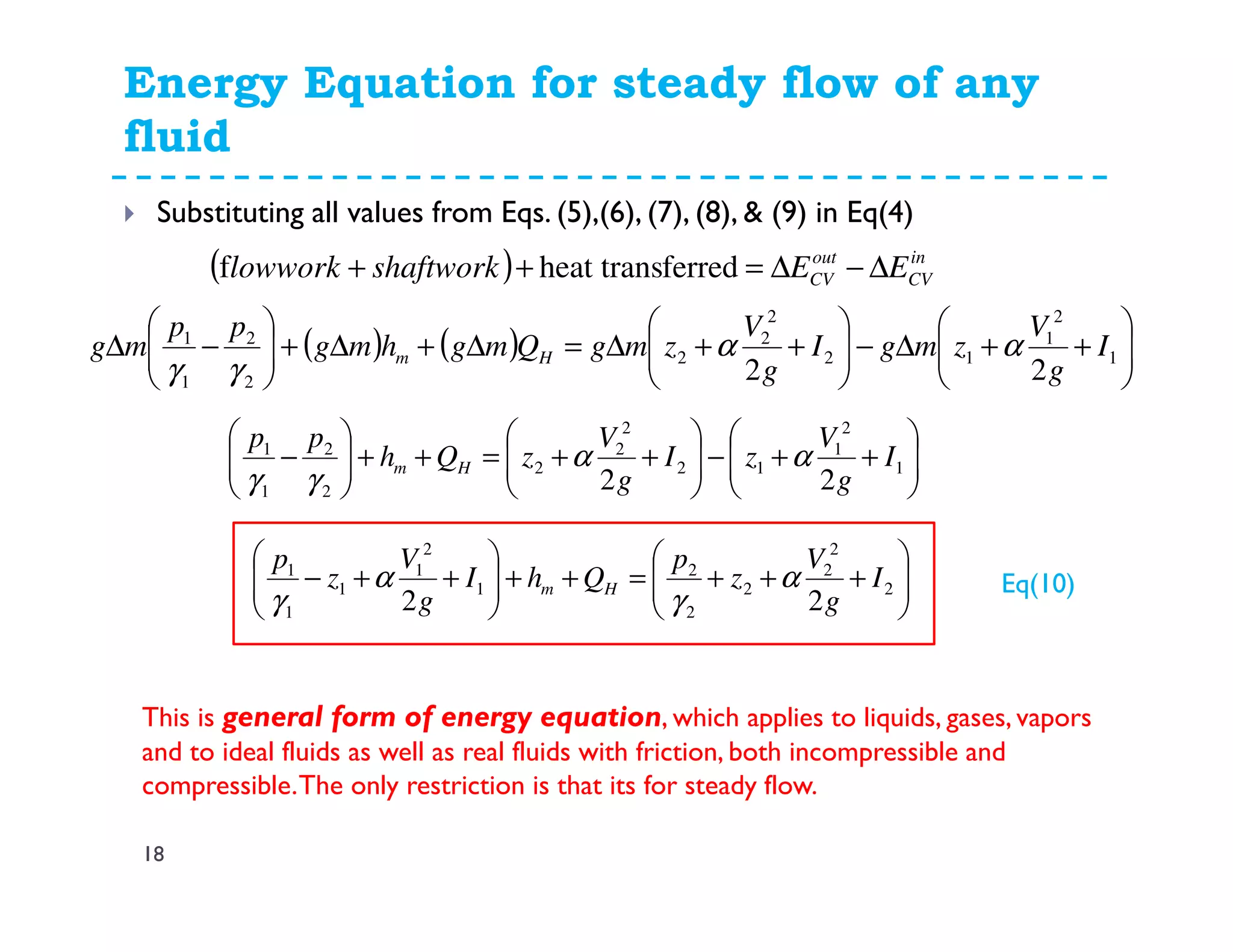
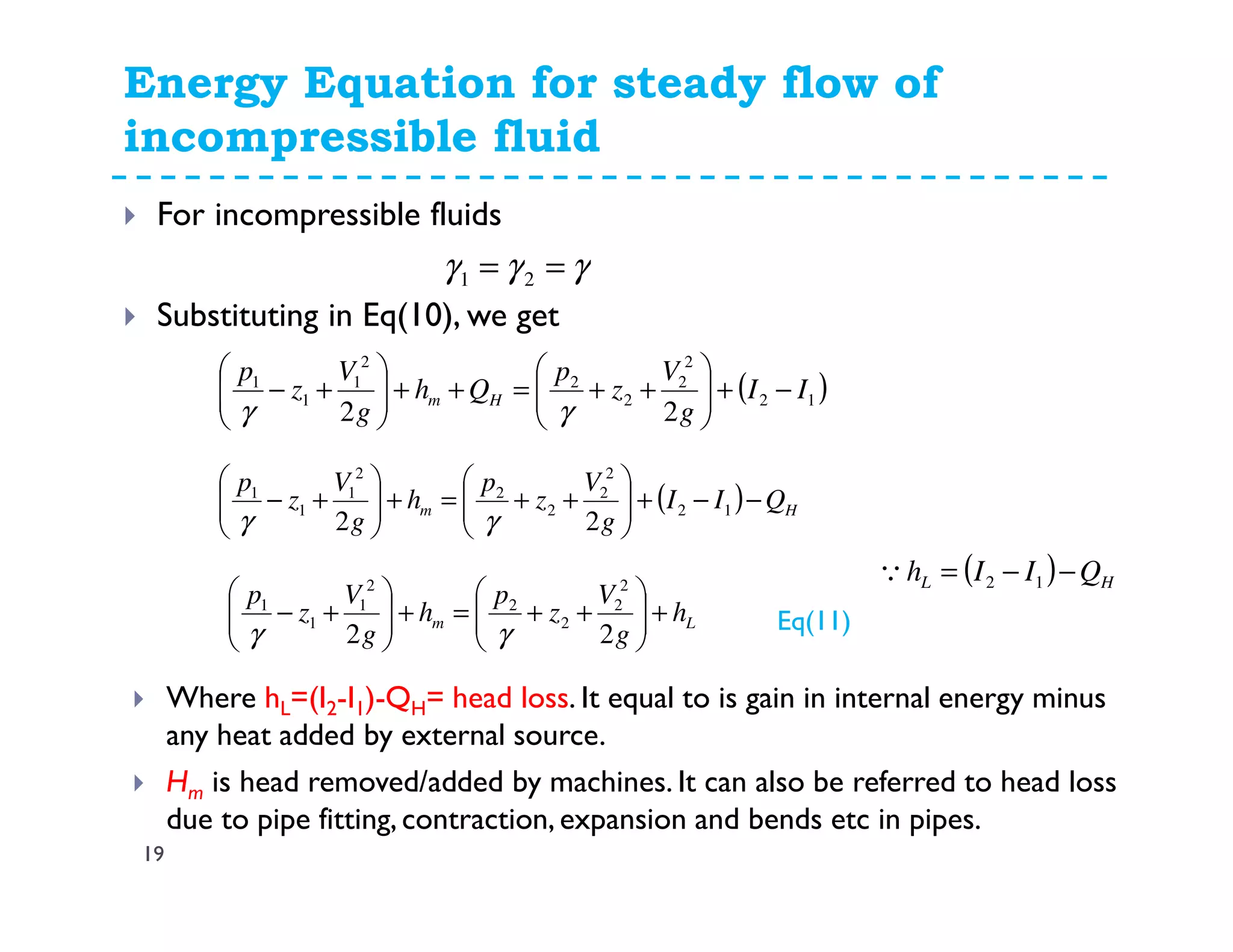
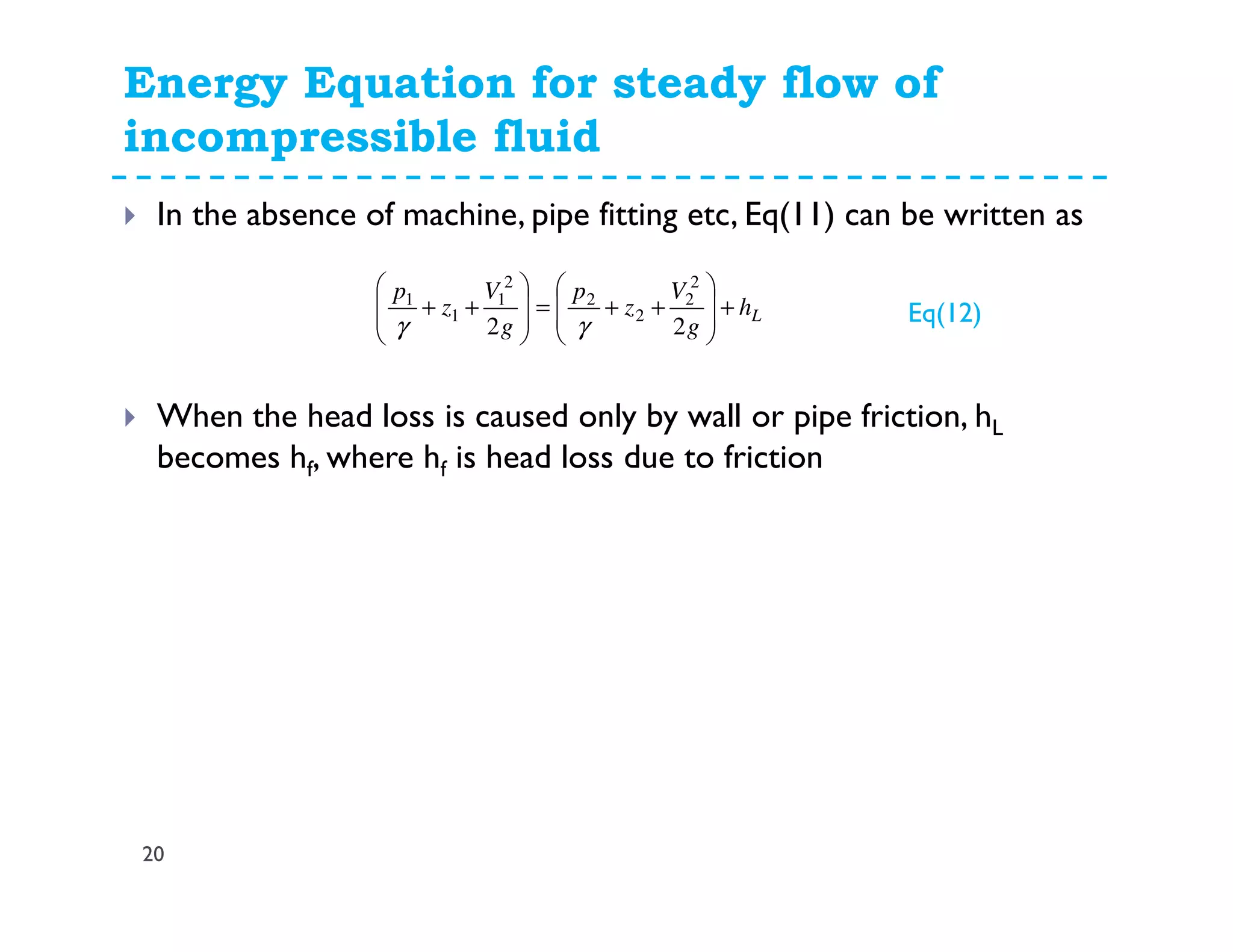
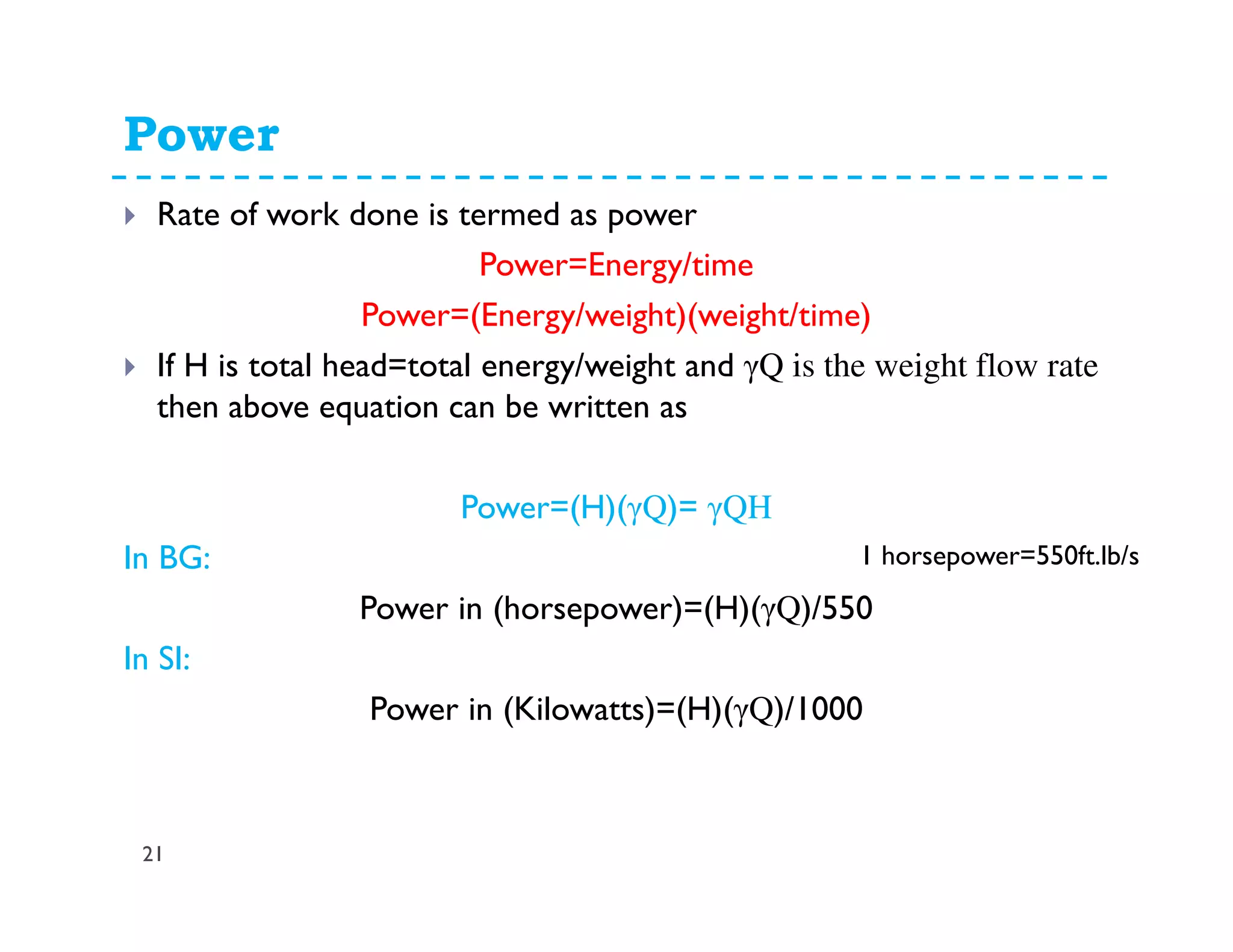
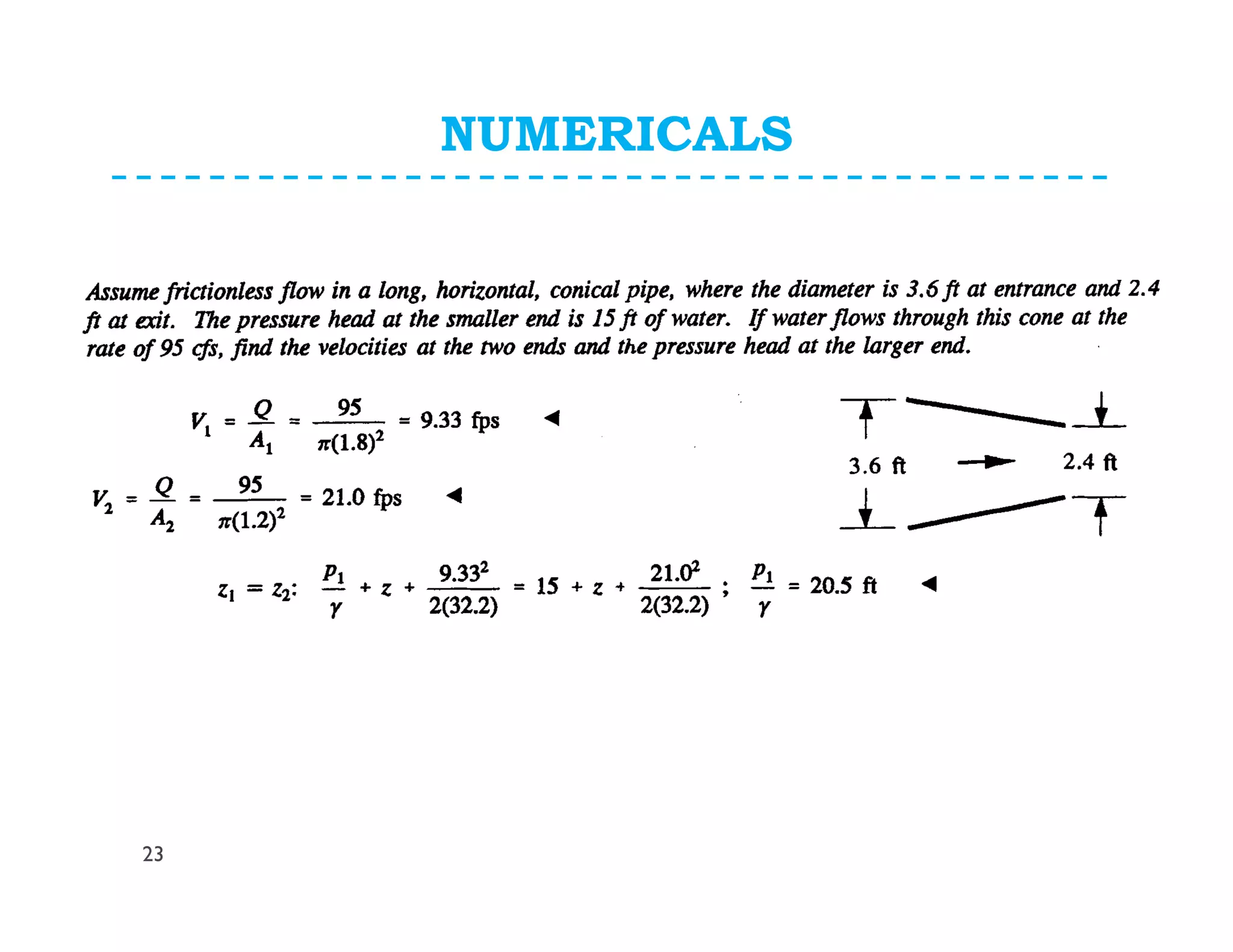
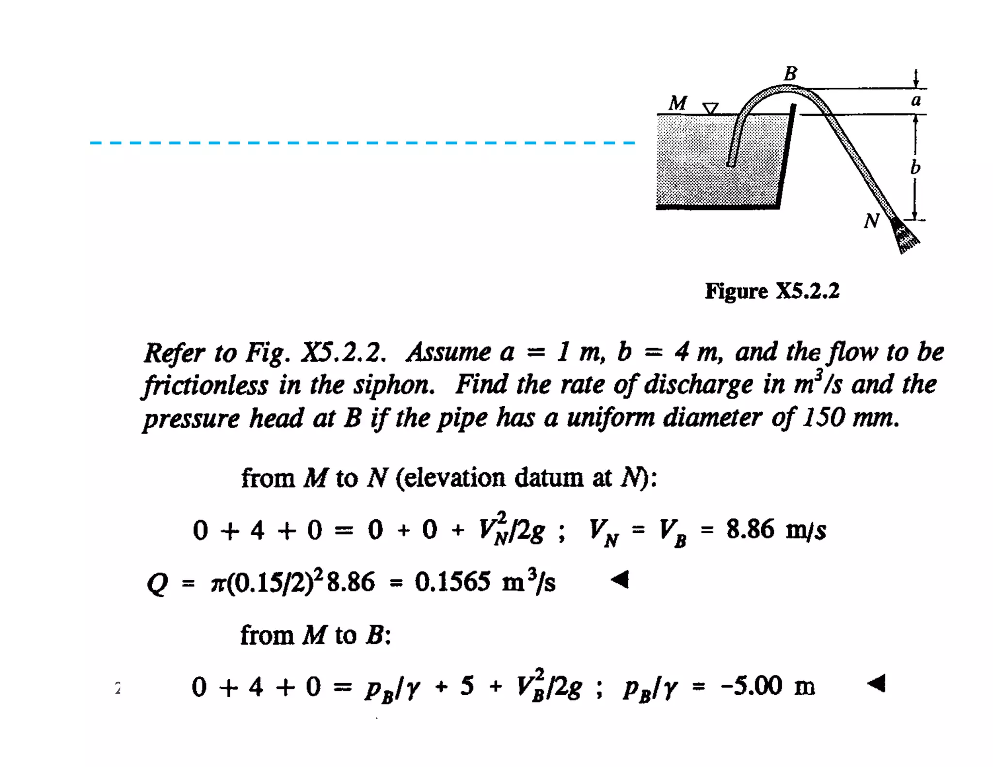
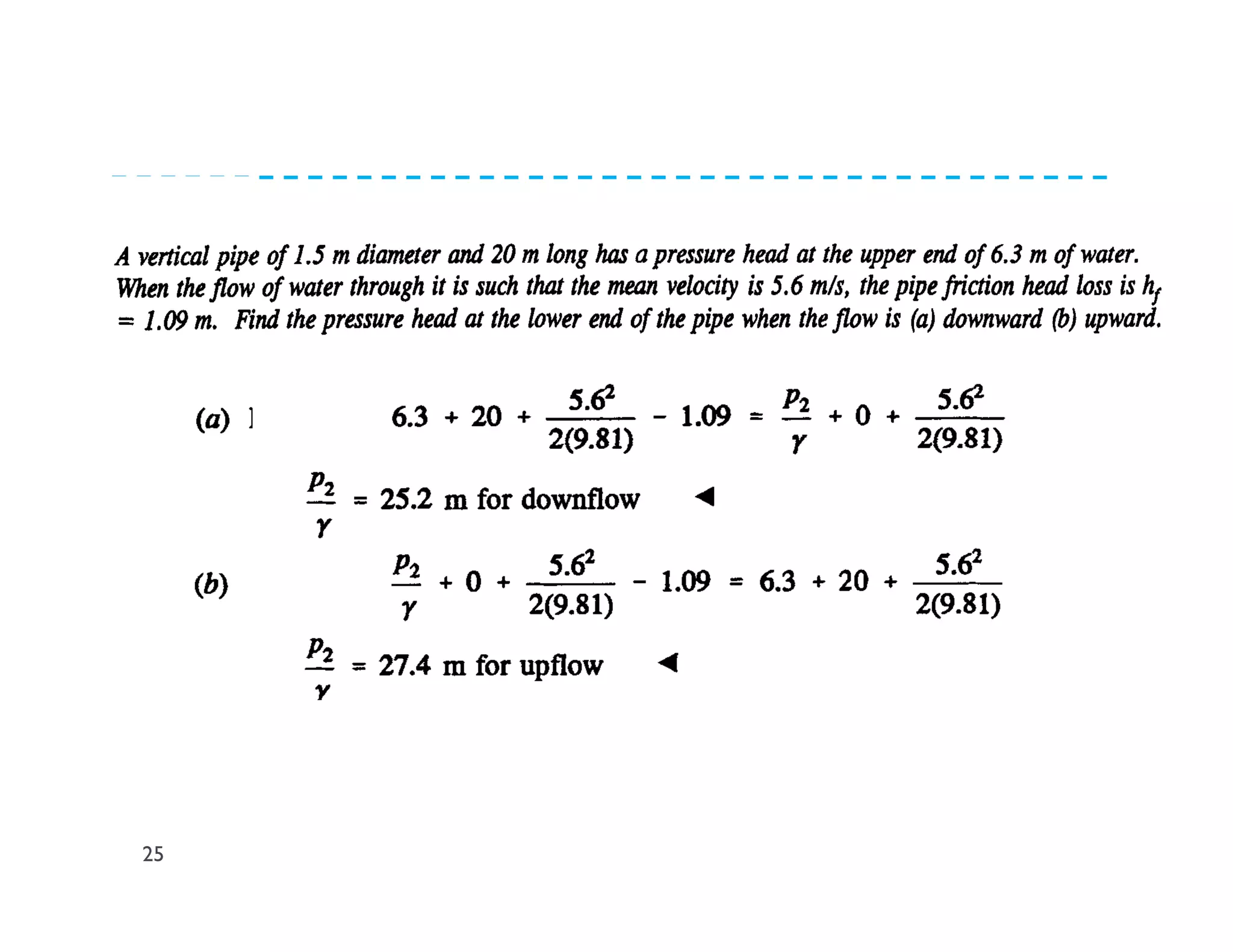
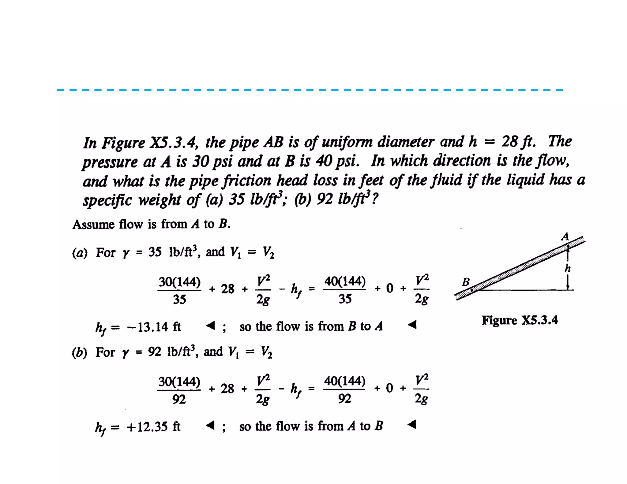
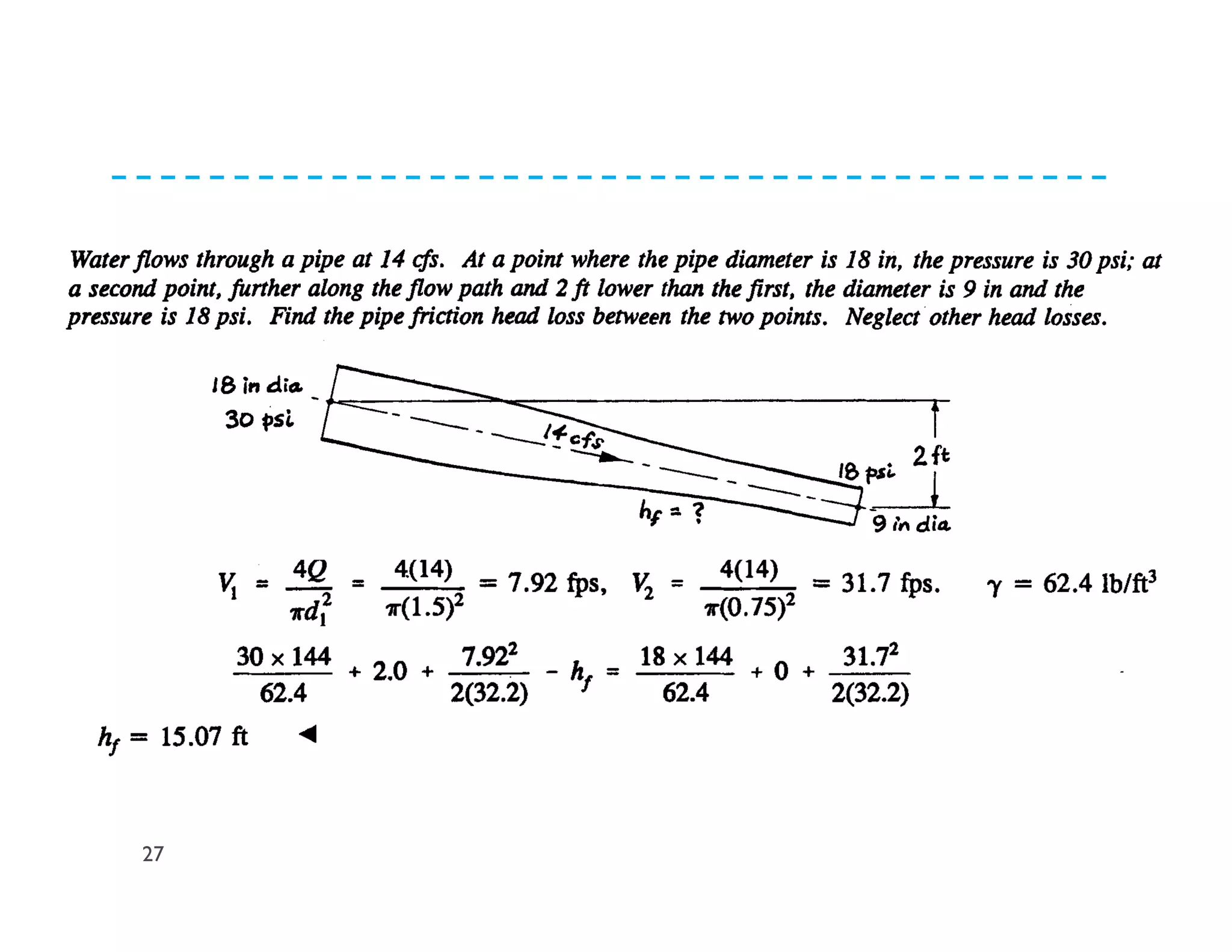
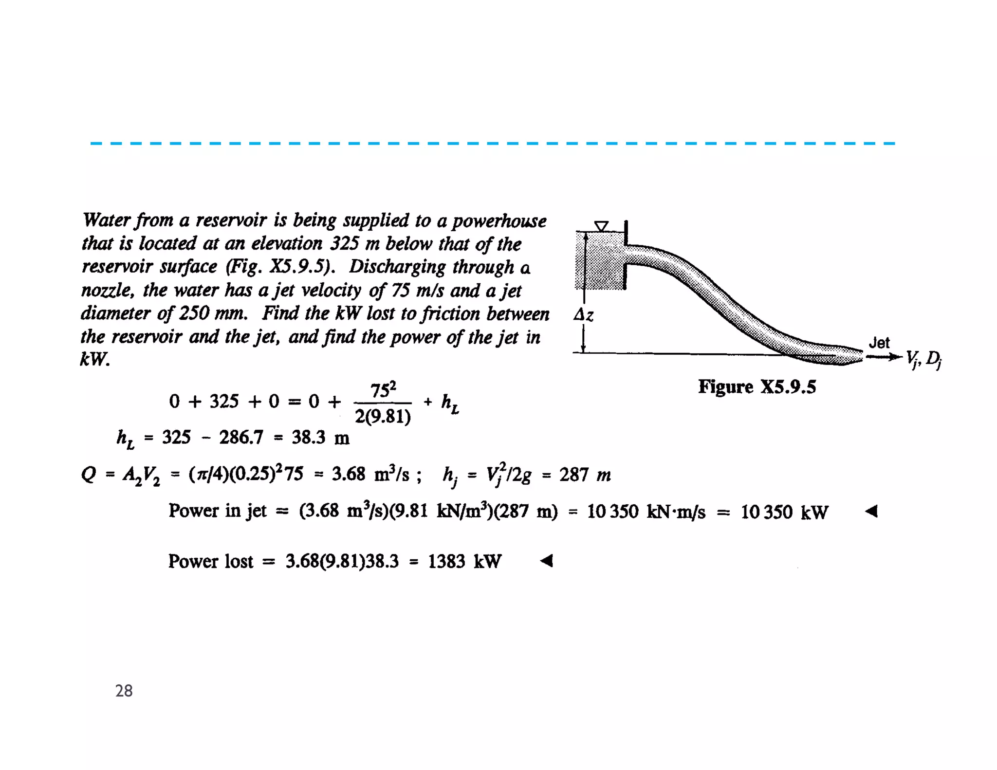
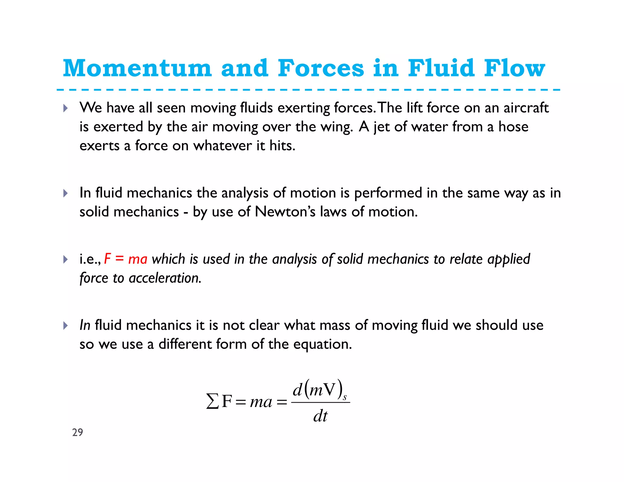
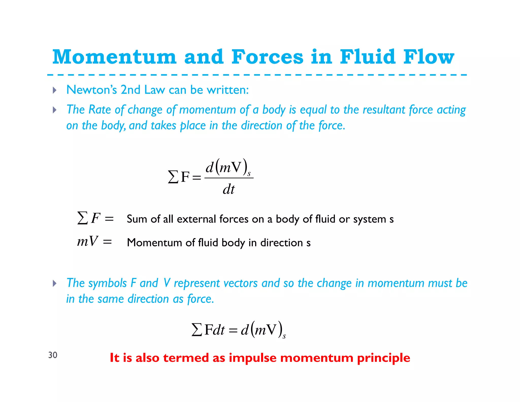

This document discusses fluid dynamics and Bernoulli's equation. It begins by defining different forms of energy in a flowing liquid, including kinetic energy, potential energy, pressure energy, and internal energy. It then derives Bernoulli's equation, which states that the total head of a fluid particle remains constant during steady, incompressible flow. The derivation considers forces acting on a fluid particle and uses conservation of energy. Finally, the document presents the general energy equation for steady fluid flow and the specific equation for incompressible fluids using the concepts of total head, head loss, and hydraulic grade line.


![FLUID DYNAMICS [EQUATION OF MOTION].pptx](https://cdn.slidesharecdn.com/ss_thumbnails/fluiddynamicsequationofmotion-250628150614-29ccfaab-thumbnail.jpg?width=640&height=640&fit=bounds)


![Unit -2b Fluid Dynamics [Compatibility Mode].pdf](https://cdn.slidesharecdn.com/ss_thumbnails/unit-2bfluiddynamicscompatibilitymode-240912163512-a36cdd14-thumbnail.jpg?width=640&height=640&fit=bounds)


![Engineering Economics: Solved exam problems [ch1-ch4]](https://cdn.slidesharecdn.com/ss_thumbnails/solvedexamproblemsch1-ch4-200220070043-thumbnail.jpg?width=640&height=640&fit=bounds)