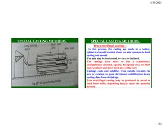
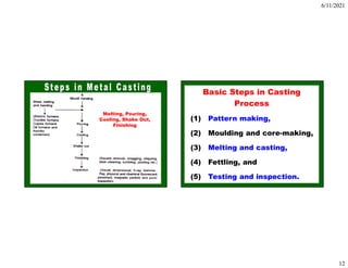
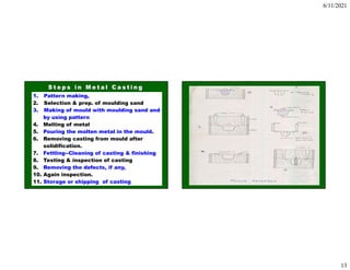
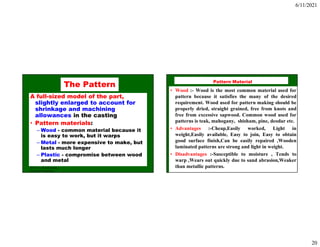
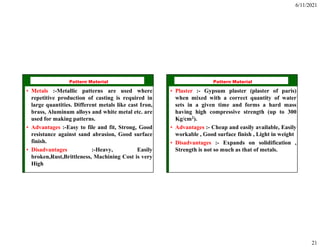
The document discusses manufacturing processes and metal casting. It covers the basic steps in the casting process, which include pattern making, molding and core making, melting and casting, fettling, and testing and inspection. It also discusses pattern materials, which can include wood, metals, plaster, plastic compounds, and waxes. The key factors in selecting a pattern material are the design, number of castings needed, quality and shape of the casting, type of molding process and material, possibility of design changes, and repetition of castings.


![6/11/2021
96
Disadvantages of shell moulding :-
Initial cost of pattern and sand is high
Special equipments are to be used.
Reuse of sand is difficult.
Maximum size is limited.
Minimum thickness of the section that can be cast
is 4mm.
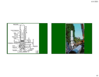
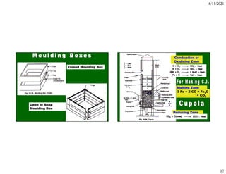
Melting (Cupola) and Pouring
Advantages of Cupola for melting C.I.: Low cost;
Better control of chemical comp.; Easier temp.
control; Tapping at regular intervals; Easily
available and less expensive fuels.
Main disadvantage-- not possible to produce iron
with < 2.8% C for certain white C.I. For this
duplex process is employed.
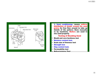
Description of a cupola
Shell-- Steel sheet 6-12 mm thick and lined
inside with acid refractory bricks [((SiO2) and
Alumina (Al2O3)]and clay. Dia.: 1-2 m. Height: 3 to
5 times the diameter.](https://image.slidesharecdn.com/unit-ime-401-240126140019-ad98d4fe/85/Manufacturing-technology-process-introduction-and-foundary-96-320.jpg)