1. Thunder Tiger Corporation guarantees this model kit to be free from defects in both material and workmanship.
The total monetary value under warranty will in no case exceed the cost of the original kit purchased. This warranty
does not cover any components damaged by use or modification. Part or parts missing from this kit must be
reported within 60 days of purchase. No part or parts will be sent under warranty without proof of purchase.
To receive part or parts under warranty, the service center must receive a proof of purchase and/or the defective
part or parts. Should you find a defective or missing part, contact the authorized Thunder Tiger Service/Distributor
nearest you. Under no circumstances can a dealer or distributor accept return of a kit if assembly has started.
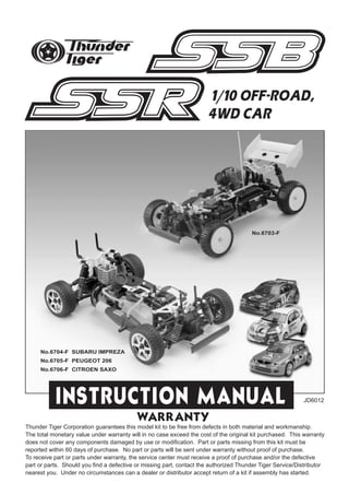
1/10 OFF-ROAD,
4WD CAR
JD6012
No.6704-F SUBARU IMPREZA
No.6705-F PEUGEOT 206
No.6706-F CITROEN SAXO
No.6703-F
2.
3. 1
2
a. Take out the 4 screws on the receiver box to remove the box top.
b. Install the servos with tap screws. Notice the orientation of the steering and throttle servo output shafts.
c. Install the receiver switch onto the rear of the receiver box with its original screws.
d. Properly plug the connectors/wires into the receiver: steering servo connector/wire into channel 1 slot, throttle servo
connector/wire into channel 2 slot, and battery switch connector/wire into battery slot.
e. Place the receiver and the wires inside the receiver box, thread the receiver antenna/wire through the box top hole, and
reinstall the box top.
f. Thread the receiver antenna/wire through the antenna tube, then install the antenna tube onto the box top hole.
g. Install 4 AA size alkaline batteries in receiver battery box and strap the battery box onto the battery plate with two large
nylon zip-ties.
h. Connect the receiver battery box wire/connector to the receiver switch wire/connector.
i. Install the battery box & plate onto the posts, then use the large body clips to secure the plate onto posts.
a. Install the threaded part of the linkage rod into the plastic tie-end. The linkage rod with tie-end should
measure 55mm when finished.
b. Install the steering linkage rod with tie-end onto steering servo horn.
c. Pop the tie-end onto the standoff ball on the steering rack, and install the servo horn onto steering sero output shaft.
INSTALLING THE RADIO GEAR skip if already assembled
INSTALLING STEERING SERVO LINKAGE skip if already assembled
2
a c
f
b
ed
ihg
a b c
55MMAFTER INSTALLATION
4. 3
3
a. Build the throttle/brake linkages as shown on the diagram.
b. Secure the brake cam lever onto brake cam with set screw.
c. Install the servo horn onto throttle sero output shaft.
INSTALLING THROTTLE LINKAGE skip if already assembled
a. Plug the charger into an AC outlet.
b. Line up the charging adapter with the tip of the glow plug igniter.
c. Pull on the glow plug igniter lever to accept the charging adapter.
d. Plug the charging adapter into the glow plug igniter. At this point, the small red LED indicator on the
charger should light up indicating the charging sequence is in progress.
e. Unplug the glow plug igniter from charger after charging is complete. Pull on the glow plug igniter
lever.
f. Pull the charging adapter out of the glow plug igniter.
Charge the new glow plug igniter for 16 to 24 hours on the first charge. For subsequent charges, charge
it about 12 hours before next use.
NOTE:
If the igniter gets warm or hot during the charge, unplug the igniter from charger immediately. A warm /
hot igniter means the igniter is overcharged. Overcharging can damage the internal battery in the igniter;
thus, shortening its life.
CHARGING THE GLOW PLUG IGNITER
4 a b c
fed
cba
Thunder Tiger Optional Part #2165, 1300MAH Glow Starter w/220V Charger.
Thunder Tiger Optional Part #2166, 1300MAH Glow Starter w/110V Charger.
To brake cam
To engine
carburetor
lever
5. 5
a. Check the frequency printed on the transmitter crystal.
b. Check the frequency printed on the receiver crystal, and make sure it matches with the transmitter
crystal. Make sure no one will operate on the same frequency when you are. When there is a radio
glitch, it will most likely be caused by improper crystal, damaged crystal, or people operating on the
same frequency.
c. Install the antenna into transmitter.
PREPARING THE RADIO
6
a. Install 8 AA-size alkaline batteries into transmitter.
b. Undo the large zip-tie, and remove the receiver battery box. Install 4 AA-size alkaline batteries into
receiver battery box.
c. Secure the receiver battery box with batteries back onto the posts with large body clips.
RADIO BATTERY INSTALLATION
a b c
4
a. When turning radio on, first turn on the transmitter.
b. Then, turn on the receiver. When turning off, first turn the receiver off, then the transmitter off.
c. To reverse the functions of servos, use the small, white servo reverse switches located on top of the
pistol transmitter (or the inset servo reverse switches located at the center of the stick transmitter). To
trim the servos on pistol transmitter, use the large, red trim levers on top and side of the steering wheel
(the top trims steering, and the side trims throttle/brake). On a stick transmitter, the trim levers are
located accordingly around the sticks.
RADIO OPERATION
a b c
7 ba c
6. 8
a. Check the radio steering functions. With the radio transmitter and receiver on, turn the steering wheel/stick
to the left. The front tires/wheels should turn left accordingly. If not, flip the steering servo reverse
switch.
b. Return the steering wheel/stick to neutral. The front tires/wheels should point straight forward. If not,
use the steering trim lever to correct it.
c. Turn the steering wheel/stick to the right. The front tires/wheels should turn right accordingly.
OPERATING RADIO STEERING FUNCTION
5
9
a. Check the radio throttle/brake functions. With the radio transmitter and receiver on, pull the trigger/push
the stick forward. The carburetor should be fully opened and the brake disengaged. To reverse this
function, flip the throttle/brake servo reverse switch.
b. Return the trigger/stick to neutral. The carburetor should be closed to a point where the idle has
been set (see step for ADJUSTING THROTTLE/BRAKE LINKAGE), and the brake still disengaged. If
not, use the throttle/brake trim lever to correct it.
c. Push the trigger/pull the stick backward. The carburetor opening should still be the same at neutral,
throttle spring compressed slightly, and the brake engaged.
OPERATING RADIO THROTTLE / BRAKE FUNCTION
a b c
a b c
7. 10
a. To set the throttle/brake linkage, first the radio should be on and neutral; thus, the servo is at neutral
position.
b. With the servo at neutral, turn and adjust the brake collar to a point where the brake lever almost
engages the brake system, but not yet.
c. With the servo at neutral, loosen the throttle collars. Then, manually close the carburetor, and set
the collar (next to the spring) with the spring slightly compressed. Then, set the other collar next to
the linkage pivot.
11
a. To set the carburetor idle (small needle sticking out from the carburetor body), turn the screw as
pictured. Initial idle setting should leave 1mm carburetor gap. Clockwise turn will provide higher idle
(larger carburetor opening), and counterclockwise turn will provide lower idle (smaller carburetor
opening).
b. To set the high speed needle (large needle sticking out from the carburetor body), turn the screw as
pictured. Initial high speed needle setting should be 2.5 turns (close the needle completely, then back
out 2.5 turns). Clockwise turn will provide leaner setting (lower fuel to air mixture), and counterclockwise
turn will provide richer setting (higher fuel to air mixture). Please refer to ENGINE BREAK-IN/SETTING
procedures to properly set the engine.
c. Remove the outer foam from filter and make it moist evenly with a few drops of fuel. If the vehicle
will be operated in an area with fine dust, use filter oil or caster oil instead of fuel. It is important that
the foam is only moist to trap dirt and allow air passage. With the foam too wet, limited air can pass
through; therefore, limiting engine performance. Finally, make sure the air cleaner boot is securely
fastened with a zip-tie.
ADJUSTING THROTTLE / BRAKE LINKAGE
a b c
ADJUSTING CARBURETOR
6
a b c
8. 12 a b c
a. Remove the cap from fuel bottle nozzle.
b. Squeeze the fuel bottle, insert into fuel, and draw fuel into the fuel bottle. The fuel used should be
methanol based model engine glow fuel (available at hobby shops) with 10% to 20% nitro content
and 5% to 18% caster/synthetic oil content for lubrication.
c. Fill car's fuel tank with glow fuel.
13
FUELLING
PREPARING THE ENGINE
a. To start an engine, first remove the glow plug.
b. Check the glow plug by plugging it into the glow plug igniter. The glow plug element should light up
brightly. If it lights up dimly, then the glow plug igniter is low (and it needs recharging). If it does not
light up or the plug element looks distorted, then the glow plug is bad (replace with new one). After
checking, reinstall the glow plug.
The glow plug used for this engine can be: Thunder Tiger 9281, McCoy #9 / #59,
Novarossi C4S / C5S / C6S,OS #8 / #A3 / #A5, and Picco P6S / P7S.
c. With the radio off, manually turn the servo to open the carburetor (open throttle).
d. Plug the tuned pipe exhaust tip.
e. Keeping the exhaust tip plugged, pull on the engine's starter. Keep doing it until fuel reaches engine's
carburetor, then pull it 3 more times to prime the engine.
f. Manually return the servo back to neutral.
7
d e
cba
f
9.
10.
11. PD6027 LEXAN BODY, SUBARU IMPREZA PD6028 DECAL, SUBARU IMPREZA
PD6029 LEXAN BODY & DECAL SET, SUBARU IMPREZA PD6030 PAINTED BODY SET, SUBARU IMPREZA
PART LIST
12
THUNDER TIGER CORPORATION
PRINTED IN TAIWAN JD0382
THUNDER TIGER CORPORATION
PRINTED IN TAIWAN JD0382
12. PD6031 LEXAN BODY, PEUGEOT 206 PD6032 DECAL, PEUGEOT 206
PD6033 LEXAN BODY & DECAL SET, PEUGEOT 206 PD6034 PAINTED BODY SET, PEUGEOT 206
PART LIST
13
THUNDER TIGER CORPORATION
PRINTED IN TAIWAN JD2708
THUNDERTIGERCORPORATION
PRINTEDINTAIWANJD2708
13. PD6035 LEXAN BODY, CITROEN SAXO PD6036 DECAL, CITROEN SAXO
PD6037 LEXAN BODY & DECAL SET, CITROEN SAXO PD6038 PAINTED BODY SET, CITROEN SAXO
PART LIST
14
THUNDER TIGER CORPORATION
PRINTED IN TAIWAN JD2708
THUNDERTIGERCORPORATION
PRINTEDINTAIWANJD2708