SlideShare a Scribd company logo
1 of 62
Download to read offline
1998-99 DRIVE AXLES
Differentials - Front - Dana 35 - Explorer, Mountaineer & Ranger
DESCRIPTION
Dana model 35 front axle is an integral carrier housing. See Fig. 2 . Axle housing is made of aluminum and is
mounted to subframe assembly. Drive pinion depth and differential side bearing preload are set by use of shims.
Pinion bearing preload is set by use of collapsible pinion spacer.
AXLE RATIO & IDENTIFICATION
Axle can be identified by axle code on Safety Certification Label on left door pillar. Also, a metal identification
tag, stamped with gear ratio and diameter, is attached to axle housing. See Fig. 1 . Limited-slip differential is
identified by "L" on tag.
Fig. 1: Identifying Axle Tag Information
Courtesy of FORD MOTOR CO.
WARNING: On vehicles with air suspension, power to air suspension must be shut
off before hoisting, jacking or towing. Failure to do so can result in
unexpected inflation or deflation of air suspension, which can result in
shifting of vehicle during servicing.
1999 Ford Explorer
1998-99 DRIVE AXLES Differentials - Front - Dana 35 - Explorer, Mountaineer & Ranger
1999 Ford Explorer
1998-99 DRIVE AXLES Differentials - Front - Dana 35 - Explorer, Mountaineer & Ranger
Helpmelearn
November-17-07 10:45:31 AM Page 1 © 2005 Mitchell Repair Information Company, LLC.
Helpmelearn
November-17-07 10:45:34 AM Page 1 © 2005 Mitchell Repair Information Company, LLC.
Fig. 2: Exploded View Of Front Axle Housing Assembly (Typical)
Courtesy of FORD MOTOR CO.
LUBRICATION
Capacity is 3.25 Pts. (1.54L) of Motorcraft SAE 80W90 Thermally Stable 4X4 Axle Lubricant (XL-80W90-
QL). Capacities listed are approximate. Fill differential until fluid level is about 1/4" below bottom of filler plug
hole.
TROUBLE SHOOTING
REMOVAL & INSTALLATION
NOTE: See appropriate table in TROUBLE SHOOTING article in GENERAL
INFORMATION.
WARNING: On vehicles with air suspension, power to air suspension must be shut
off before hoisting, jacking or towing. Failure to do so can result in
unexpected inflation or deflation of air suspension, which can result in
shifting of vehicle during servicing.
1999 Ford Explorer
1998-99 DRIVE AXLES Differentials - Front - Dana 35 - Explorer, Mountaineer & Ranger
Helpmelearn
November-17-07 10:45:31 AM Page 2 © 2005 Mitchell Repair Information Company, LLC.
AXLE SHAFT, BEARING & OIL SEAL
Removal
Remove right axle shaft. See 4WD AXLE SHAFTS - FRONT - EXPLORER, MOUNTAINEER & RANGER
article. Remove axle from axle housing. Using Converter Seal Remover (T94P-77001-BH) and slide hammer,
remove axle tube seal. Using Bearing Remover (T94P-77001-KH) and slide hammer, remove axle tube bearing.
Installation
1. Ensure bearing bore is clean and undamaged. Using Bearing Installer (T95T-1175-D) and Driver Handle
(T80T-4000-W), install bearing in axle tube, .88" (44.5 mm) below outer lip of axle tube. Coat lip of seal
with multipurpose grease. Using Seal Installer (T95T-3010-A) and Driver Handle (T80T-4000-W), install
axle tube seal.
2. To complete installation, reverse removal procedure. Tighten all nuts and bolts or specification. See
TORQUE SPECIFICATIONS . Fill differential with proper lubricant until fluid level is about 1/4"
below bottom of filler plug hole. See LUBRICATION .
AXLE HOUSING ASSEMBLY
Removal & Installation
1. Raise and support vehicle. Remove both front axle shafts. See 4WD AXLE SHAFTS - FRONT -
EXPLORER, MOUNTAINEER & RANGER article. Scribe alignment marks on drive shaft and pinion
flange for installation reference. Remove driveshaft-to-pinion flange bolts, and wire drive shaft aside.
2. Disconnect axle housing vent hose. Using a suitable jack, support axle housing, and secure axle housing
to jack. Remove 3 front axle housing-to-frame nuts and bolts. Lower floor jack, and remove axle housing
assembly.
3. To install, reverse removal procedure. Tighten all nuts and bolts to specification. See TORQUE
SPECIFICATIONS . Fill differential with proper lubricant until fluid level is about 1/4" below bottom
of filler plug hole. See LUBRICATION .
PINION FLANGE & OIL SEAL
Removal
1. Raise and support vehicle. Scribe alignment marks on drive shaft and pinion flange for installation
reference. Remove driveshaft-to-pinion flange bolts, and wire drive shaft aside. Using an INCH-lb. torque
wrench, measure and record torque required to rotate pinion through several revolutions.
2. Hold pinion flange and remove pinion nut. Scribe index marks on pinion flange and pinion stem for
installation reference. Remove pinion flange. Using Converter Seal Remover (T94P-77001-BH) and slide
hammer, remove pinion seal.
NOTE: Pinion flange and oil seal replacement affects bearing preload. Preload must be
carefully reset during reassembly.
1999 Ford Explorer
1998-99 DRIVE AXLES Differentials - Front - Dana 35 - Explorer, Mountaineer & Ranger
Helpmelearn
November-17-07 10:45:31 AM Page 3 © 2005 Mitchell Repair Information Company, LLC.
Installation
1. Ensure pinion shaft splines are free of burrs. Remove burrs with fine crocus cloth if necessary. Lubricate
area between oil seal lip. Using Pinion Oil Seal Replacer (T79P-4676-A), install oil seal into axle
housing.
2. Align marks on pinion flange and pinion stem. Apply a small amount of lubricant to pinion flange
splines. Install pinion flange and NEW pinion nut. Hold pinion flange, and gradually tighten nut while
rotating pinion.
3. Check pinion bearing preload often, until correct preload is obtained. DO NOT back off pinion nut to
reduce preload. See DIFFERENTIAL SPECIFICATIONS . Connect rear end of drive shaft to pinion
flange, aligning scribed marks.
4. Apply locking compound to drive shaft bolt threads and tighten bolts to specification. See TORQUE
SPECIFICATIONS . Fill differential with proper lubricant until fluid level is about 1/4" below bottom
of filler plug hole. See LUBRICATION .
OVERHAUL
DISASSEMBLY
1. Remove axle housing. See AXLE HOUSING ASSEMBLY under REMOVAL & INSTALLATION.
Mount axle housing in Holding Fixture (T57L-500-B) using Adapters (T90T-4000-A) and Spacer (T80T-
4000-B2). Remove housing cover, and drain differential fluid.
2. Remove axle shaft from axle housing. Using Converter Seal Remover (T94P-77001-BH) and slide
hammer, remove right and left axle tube seal. Using Bearing Remover (T94P-77001-KH) and slide
hammer, remove right and left axle tube bearings (if necessary).
3. Note matched numbers or letters on differential bearing caps and carrier for reassembly reference.
Remove bearing caps. Install Housing Spreader Adapter Set (T90T-4000-A) and Differential Housing
Spreader (TOOL-4000-E). See Fig. 3 . Mount dial indicator onto axle housing to measure amount of
spread.
4. Spread axle housing to .020" (.51 mm). Remove dial indicator. Carefully pry differential assembly out of
housing. Remove spreader immediately so housing does not permanently distort. Remove and tag side
bearing races to indicate from which side of carrier they were removed.
5. Turn nose of axle housing up. Using an INCH lbs. torque wrench, measure and record pinion bearing
NOTE: If oil seal becomes cocked during installation, remove seal and install NEW oil
seal.
NOTE: If desired preload is exceeded, a NEW collapsible spacer must be
installed. Tighten nut to obtain proper preload.
CAUTION: DO NOT spread carrier housing more than .030" (.76 mm), since
permanent damage to housing could result.
1999 Ford Explorer
1998-99 DRIVE AXLES Differentials - Front - Dana 35 - Explorer, Mountaineer & Ranger
Helpmelearn
November-17-07 10:45:31 AM Page 4 © 2005 Mitchell Repair Information Company, LLC.
preload. Hold pinion flange and remove pinion nut. Scribe index marks on pinion flange and pinion stem
for installation reference. Remove pinion flange. Using Converter Seal Remover (T94P-77001-BH) and
slide hammer, remove pinion seal.
6. Remove drive pinion by tapping with soft-face mallet. Remove outer pinion bearing and oil slinger. Drive
out inner and outer drive pinion bearing race using Pinion Bearing Race Remover (T86T-4628-BH) and
Driver Handle (T80T-4000-W). Press pinion bearing off pinion. Measure and record inner pinion bearing
shim thickness.
7. Place differential case into vise, with rags underneath to protect ring gear. Remove and discard ring gear
bolts. Tap ring gear with soft-face mallet to remove ring gear from case. Using drift and hammer, drive
out pinion shaft lock pin. Remove pinion shaft.
8. Rotate side gears until pinion gears are aligned with case opening. Remove pinion gears and thrust
washers. Remove side gears with thrust washers. Using universal bearing remover, remove inner pinion
bearing and oil slinger from drive pinion.
Fig. 3: Spreading Axle Housing
Courtesy of FORD MOTOR CO.
CLEANING & INSPECTION
1999 Ford Explorer
1998-99 DRIVE AXLES Differentials - Front - Dana 35 - Explorer, Mountaineer & Ranger
Helpmelearn
November-17-07 10:45:31 AM Page 5 © 2005 Mitchell Repair Information Company, LLC.
1. Clean all components in solvent. Allow bearings to air dry. Inspect all machined surfaces for smoothness
or raised edges. Inspect all gear teeth for wear or chipping, and replace as necessary.
2. Check all bearings and races for nicks, roller end wear, grooves or damage. Replace as needed. Check
pinion flange for wear in sealing area and replace as necessary.
3. Check differential pinion shaft, pinion gears, side gears and thrust washers for wear or damage. Replace
all defective parts. Replace pinion gear and ring gear as a set.
REASSEMBLY
1. Install thurst washers onto differential side gears. Install differential side greas into differential housing.
Install trurst washer and pinion gear into differential case. Install pinion shaft. Install pinion shaft roll pin.
2. Using Pinion Bearing Cup Replacer (T67P-4616-A), install pinion bearing cups. If using old ring and
pinion gear set, go to next step. If using new ring and pinion gear set, go to step 8 .
3. Apply a light film of oil to pinion bearing. Assemble Pinion Depth Gauge (T79P-4020-A). Install
aligning adapter, gauge disc and screw. Place rear pinion bearing over aligning adapter and into bearing
cup of carrier housing. See Fig. 4 .
4. Install front pinion bearing into front bearing cup. Place handle onto screw and tighten to 20 INCH lbs.
(2.25 N.m). See Fig. 5 . Ensure pinion depth measuring tool is properly installed and tightened.
5. Rotate gauge block several times to seat bearings. Rotational torque on gauge block assembly should be
20 INCH lbs. (2.25 N.m) with new bearings. Final position of gauge block should be 45 degrees above
axle shaft center line. See Fig. 6 .
6. Clean differential bearing bores thoroughly, and install gauge tube. Tighten differential bearing cap bolts
to specification. See TORQUE SPECIFICATIONS . Use flat pinion shims as a gauge for shim
selection. Hold gauge block in proper position, and measure clearance between gauge block and tube.
7. Correct shim selection is accomplished when a slight drag is felt as shim is drawn between gauge block
and tube. Shims are available in various thicknesses. Install correct shim on pinion for reassembly. Pinion
bearings must be installed in the same location as during pinion depth measurement. Remove measuring
equipment and go to step 9 .
8. Notice the plus (+), minus (-) or zero (0) etching on both old and new pinion and adjust thickness of new
shim according to charts in illustration. See Fig. 7 . Go to next step.
9. Place pinion shim previously determine on pinion shaft and press on inner pinion bearing. Place NEW
collapsible spacer on pinion shaft. Install outer pinion bearing and oil slinger in axle housing. Using
Pinion Oil Seal Replacer (T79P-4676-A), install oil seal into axle housing.
10. Position pinion gear in axle housing. Align marks on pinion flange and pinion stem. Apply a small
amount of lubricant to pinion flange splines. Install pinion flange and NEW pinion nut. Hold pinion
flange, and gradually tighten nut while rotating pinion.
NOTE: If oil seal becomes cocked during installation, remove seal and install
NEW oil seal.
NOTE: If desired preload is exceeded, a NEW collapsible spacer must be
installed. Tighten nut to obtain proper preload.
1999 Ford Explorer
1998-99 DRIVE AXLES Differentials - Front - Dana 35 - Explorer, Mountaineer & Ranger
Helpmelearn
November-17-07 10:45:31 AM Page 6 © 2005 Mitchell Repair Information Company, LLC.
11. Check pinion bearing preload often, until correct preload is obtained. DO NOT back off pinion nut to
reduce preload. See DIFFERENTIAL SPECIFICATIONS . Remove differential bearing and install
Right Master Bearing (T93P-4222-B) and Left Master Bearing (T93P-4222-A) on differential housing.
12. Insert differential and master bearings into axle housing. Position dial indicator to outside mounting hole.
Position indicator tip on machined surface of differential case flange. Adjust dial indicator to measure full
travel. Push differential case left and right as far as possible. Measure total end play and record on Line-A
of differential bearing shim selection procedure work sheet. See Fig. 9 .
13. Remove differential case from carrier to install ring gear. Ensure ring is free of any nicks or burrs. Press
ring gear onto case, and tighten bolts to correct torque. See TORQUE SPECIFICATIONS . Install
differential case with master bearings into axle housing.
14. With dial indicator in place, push ring gear to mesh with pinion gear. Rock ring gear to allow full mesh
with pinion gear. Zero dial indicator. Move ring gear away from pinion gear as much as possible. Record
measurement on Line-B of differential bearing shim selection procedure work sheet. Remove differential
from housing, and remove master bearing from carrier assembly.
15. Identify and mark right and left bearing for installation reference. Clamp Bearing Preload Tool (T93P-
4220-AR) base in a soft-jaw vise. Keep bearing mounting surface above vise jaws. Position bearing
assembly on bearing preload tool base, and tighten tool bolt to 20 INCH lbs. (2.3 N.m). See Fig. 8 .
16. Invert preload tool and clamp bolt head in vise. Position depth micrometer over top of bearing. With
depth micrometer positioned on bearing cone, measure height of each individual bearing assembly.
Measure distance from bearing cone to bearing preload tool disc. Record both bearing measurements on
Line-D on differential bearing shim selection procedure work sheet.
17. Select appropriate bearing shims using differential bearing shim selection procedure work sheet. See Fig.
9 . For correct shim, see DIFFERENTIAL SHIM SIZE table.
18. Remove master bearing from carrier, and press appropriate differential bearing on appropriate side of
differential case. Tighten housing spreader so dial indicator reads .030" (.762 mm). Install selected shims.
19. Install differential assembly in axle housing. Install and tighten bearing caps to specification with housing
spreader still installed. See TORQUE SPECIFICATIONS . Loosen and remove spreader. Move dial
indicator base and mount in line with ring gear.
20. Mount dial indicator, and zero indicator on any ring gear drive tooth. See Fig. 10 . Turn ring gear without
turning pinion gear to measure backlash. Preferred backlash is .005-008" (.127-.203 mm).
21. If backlash is not to specification, adjust backlash by increasing thickness of one shim and decreasing
thickness of other shim by same amount. See RING GEAR BACKLASH-TO-SHIM THICKNESS
CONVERSION table. See Fig. 11 .
22. To complete assembly, reverse disassembly procedure. Tighten all nuts and bolts to specification. See
TORQUE SPECIFICATIONS . Fill differential with proper lubricant until fluid level is about 1/4"
below bottom of filler plug hole. See LUBRICATION .
DIFFERENTIAL SHIM SIZE
Color No. Of Stripes Shim Thickness - In. (mm)
Red 1 .2410-.2415 (6.121-6.134)
Red 2 .2430-.2435 (6.172-6.185)
Orange 1 .2450-.2455 (6.223-6.236)
Orange 2 .2470-.2475 (6.274-6.287)
1999 Ford Explorer
1998-99 DRIVE AXLES Differentials - Front - Dana 35 - Explorer, Mountaineer & Ranger
Helpmelearn
November-17-07 10:45:31 AM Page 7 © 2005 Mitchell Repair Information Company, LLC.
RING GEAR BACKLASH-TO-SHIM THICKNESS CONVERSION
Orange 3 .2490-.2495 (6.325-6.337)
Orange 4 .2510-.2515 (6.375-6.388)
Orange 5 .2530-.2535 (6.426-6.439)
Yellow 1 .2550-.2555 (6.477-6.490)
Yellow 2 .2570-.2575 (6.528-6.541)
Yellow 3 .2590-.2595 (6.579-6.591)
Yellow 4 .2610-.2615 (6.629-6.642)
Yellow 5 .2630-.2635 (6.680-6.693)
White 1 .2650-.2655 (6.731-6.744)
White 2 .2670-.2675 (6.782-6.795)
White 3 .2690-.2695 (6.833-6.845)
White 4 .2710-.2715 (6.883-6.896)
White 5 .2730-.2735 (6.934-6.947)
Green 1 .2750-.2755 (6.985-6.998)
Green 2 .2770-.2775 (7.036-7.049)
Green 3 .2790-.2795 (7.087-7.099)
Green 4 .2810-.2815 (7.137-7.150)
Green 5 .2830-.2835 (7.188-7.201)
Pink 1 .2850-.2855 (7.239-7.252)
Pink 2 .2870-.2875 (7.290-7.303)
Pink 3 .2890-.2895 (7.341-7.353)
Pink 4 .2910-.2915 (7.391-7.404)
Pink 5 .2930-.2935 (7.442-7.455)
Blue 2 .2970-.2975 (7.544-7.557)
Blue 3 .2990-.2995 (7.595-7.607)
Blue 4 .3010-.3015 (7.645-7.658)
Blue 5 .3030-.3035 (7.696-7.709)
Gray 1 .3050-.3055 (7.747-7.760)
Gray 2 .3070-.3075 (7.798-7.811)
Required Change In Backlash - In. (mm) Required Change In Shim Thickness - In. (mm)
.001 (.03) .002 (.05)
.002 (.05) .002 (.05)
.003 (.08) .004 (.10)
.004 (.10) .006 (.15)
.005 (.13) .006 (.15)
.006 (.15) .008 (.20)
.007 (.18) .010 (.25)
.008 (.20) .010 (.25)
.009 (.23) .012 (.30)
1999 Ford Explorer
1998-99 DRIVE AXLES Differentials - Front - Dana 35 - Explorer, Mountaineer & Ranger
Helpmelearn
November-17-07 10:45:31 AM Page 8 © 2005 Mitchell Repair Information Company, LLC.
Fig. 4: Assembling Pinion Depth Gauge
Courtesy of FORD MOTOR CO.
.010 (.25) .014 (.36)
.011 (.28) .014 (.36)
.012 (.30) .016 (.41)
.013 (.33) .018 (.46)
.014 (.36) .018 (.46)
.015 (.38) .020 (.51)
1999 Ford Explorer
1998-99 DRIVE AXLES Differentials - Front - Dana 35 - Explorer, Mountaineer & Ranger
Helpmelearn
November-17-07 10:45:31 AM Page 9 © 2005 Mitchell Repair Information Company, LLC.
Fig. 5: Installing Pinion Depth Gauge
Courtesy of FORD MOTOR CO.
1999 Ford Explorer
1998-99 DRIVE AXLES Differentials - Front - Dana 35 - Explorer, Mountaineer & Ranger
Helpmelearn
November-17-07 10:45:31 AM Page 10 © 2005 Mitchell Repair Information Company, LLC.
Fig. 6: Final Position Of Pinion Depth Gauge
Courtesy of FORD MOTOR CO.
1999 Ford Explorer
1998-99 DRIVE AXLES Differentials - Front - Dana 35 - Explorer, Mountaineer & Ranger
Helpmelearn
November-17-07 10:45:31 AM Page 11 © 2005 Mitchell Repair Information Company, LLC.
Fig. 7: Pinion Depth Shim Adjustment Charts
Courtesy of FORD MOTOR CO.
1999 Ford Explorer
1998-99 DRIVE AXLES Differentials - Front - Dana 35 - Explorer, Mountaineer & Ranger
Helpmelearn
November-17-07 10:45:31 AM Page 12 © 2005 Mitchell Repair Information Company, LLC.
Fig. 8: Positioning Bearing Preload Tool
Courtesy of FORD MOTOR CO.
1999 Ford Explorer
1998-99 DRIVE AXLES Differentials - Front - Dana 35 - Explorer, Mountaineer & Ranger
Helpmelearn
November-17-07 10:45:31 AM Page 13 © 2005 Mitchell Repair Information Company, LLC.
Fig. 9: Differential Bearing Shim Selection Procedure Work Sheet
Courtesy of FORD MOTOR CO.
1999 Ford Explorer
1998-99 DRIVE AXLES Differentials - Front - Dana 35 - Explorer, Mountaineer & Ranger
Helpmelearn
November-17-07 10:45:31 AM Page 14 © 2005 Mitchell Repair Information Company, LLC.
Fig. 10: Checking Ring Gear Backlash
Courtesy of FORD MOTOR CO.
1999 Ford Explorer
1998-99 DRIVE AXLES Differentials - Front - Dana 35 - Explorer, Mountaineer & Ranger
Helpmelearn
November-17-07 10:45:31 AM Page 15 © 2005 Mitchell Repair Information Company, LLC.
Fig. 11: Adjusting Ring Gear Backlash
Courtesy of FORD MOTOR CO.
DIFFERENTIAL SPECIFICATIONS
AXLE ASSEMBLY SPECIFICATIONS
TORQUE SPECIFICATIONS
Application In. (mm)
Ring Gear-To-Pinion Backlash (1) .005-.008 (.13-.20)
INCH Lbs. (N.m)
Drive Pinion Bearing Preload
New Bearings 15-35 (1.7-4.0)
Used Bearings 8-14 (.9-1.6)
(1) Maximum backlash variation between 3 equally spaced check points is .003" (.08 mm).
Application Ft. Lbs. (N.m)
Drive Shaft Bolt 11-15 (15-20)
1999 Ford Explorer
1998-99 DRIVE AXLES Differentials - Front - Dana 35 - Explorer, Mountaineer & Ranger
Helpmelearn
November-17-07 10:45:31 AM Page 16 © 2005 Mitchell Repair Information Company, LLC.
Front Axle Housing-To-Frame Bolt 45-59 (61-80)
Housing Cover Bolt 20-25 (27-34)
Ring Gear Bolt 70-89 (95-121)
Side Bearing Cap Bolt 47-67 (64-91)
Wheel Lug Nuts 100 (136)
1999 Ford Explorer
1998-99 DRIVE AXLES Differentials - Front - Dana 35 - Explorer, Mountaineer & Ranger
Helpmelearn
November-17-07 10:45:32 AM Page 17 © 2005 Mitchell Repair Information Company, LLC.
1997-99 DRIVE AXLES
Differential - Front - 8.8" Ring Gear - Expedition, "F" Series Light Duty, Mountaineer &
Navigator
DESCRIPTION & OPERATION
A half-shaft type front axle is used. Axle is of integral carrier housing, hypoid gear type. Drive pinion and ring
gear bearing adjustments are all accomplished with shims. Power is transmitted through transfer case driveshaft
to the drive pinion located in the axle housing. Drive pinion shaft is supported by 2 opposed tapered roller
bearings. Power is transmitted from pinion gear through ring gear and differential pinion gears to axle shafts
and wheels.
On all models except 1999 Expedition and Navigator, a vacuum operated clutch engages front axle. 1999
Expedition and Navigator is an all wheel drive vehicle. Front axle is engaged at all time. See Fig. 1 or Fig. 2 .
Fig. 1: Exploded View Of Front Axle Housing Assembly (Except 1999 Expedition & Navigator)
Courtesy of FORD MOTOR CO.
1999 Ford Explorer
1997-99 DRIVE AXLES Differential - Front - 8.8" Ring Gear - Expedition, "F" Series Light Duty, Mountaineer & Navigator
1999 Ford Explorer
1997-99 DRIVE AXLES Differential - Front - 8.8" Ring Gear - Expedition, "F" Series Light Duty, Mountaineer & Navigator
Helpmelearn
November-17-07 10:46:09 AM Page 1 © 2005 Mitchell Repair Information Company, LLC.
Helpmelearn
November-17-07 10:46:12 AM Page 1 © 2005 Mitchell Repair Information Company, LLC.
Fig. 2: Exploded View Of Front Axle Housing Assembly (1999 Expedition & Navigator)
Courtesy of FORD MOTOR CO.
AXLE RATIO & IDENTIFICATION
Axle application can be determined through the axle code on the Safety Certification Label on left door pillar.
Additionally, a metal identification tag stamped with gear ratio and diameter is secured to axle housing. See
Fig. 3 .
1999 Ford Explorer
1997-99 DRIVE AXLES Differential - Front - 8.8" Ring Gear - Expedition, "F" Series Light Duty, Mountaineer & Navigator
Helpmelearn
November-17-07 10:46:09 AM Page 2 © 2005 Mitchell Repair Information Company, LLC.
Fig. 3: Identifying Axle Identification Tag
Courtesy of FORD MOTOR CO.
LUBRICATION
Capacity is 3.5-3.7 Pts. (1.8-2.0L) of Motorcraft SAE 75W90 Thermally Stable 4X4 Axle Lubricant (XY-
75W90-QL). Capacities listed are approximate. Fill differential until fluid level is about 1/4" below bottom of
filler plug hole.
TROUBLE SHOOTING
REMOVAL & INSTALLATION
AXLE HOUSING ASSEMBLY
Removal & Installation
NOTE: See appropriate table in TROUBLE SHOOTING article in GENERAL
INFORMATION.
WARNING: On vehicles with air suspension, power to air suspension must be shut
off before hoisting, jacking or towing. Failure to do so can result in
unexpected inflation or deflation of air suspension, which can result in
shifting of vehicle during servicing.
NOTE: DO NOT allow drive shaft to hang unsupported.
1999 Ford Explorer
1997-99 DRIVE AXLES Differential - Front - 8.8" Ring Gear - Expedition, "F" Series Light Duty, Mountaineer & Navigator
Helpmelearn
November-17-07 10:46:09 AM Page 3 © 2005 Mitchell Repair Information Company, LLC.
1. Raise and support vehicle. Mark pinion yoke and drive shaft alignment for reassembly reference.
Disconnect drive shaft from yoke, and wire aside. Remove axle shaft-to-stub axle retaining bolts and wire
aside (both sides). Disconnect vent tube. Disconnect front axle actuator motor vacuum line (if equipped).
2. Using a suitable jack, support axle housing assembly and secure axle housing to jack. Remove axle
housing support bracket. Remove axle housing retaining bolts. To install, reverse removal procedure.
Tighten bolts to specification. See TORQUE SPECIFICATIONS table.
OVERHAUL (EXCEPT 1999 EXPEDITION & NAVIGATOR)
DISASSEMBLY
1. Remove axle housing. See AXLE HOUSING ASSEMBLY under REMOVAL & INSTALLATION.
Drain differential fluid. Remove housing cover. Mount axle housing in Holding Fixture (T57L-500-B)
using Adapters (T90T-4000-A) and Spacer (T80T-4000-B2).
2. Pull back clutch boot and remove snap ring. Remove front axle actuator motor. Remove axle housing
retaining bolts and remove assembly. Remove cluster gear thrust washer. Remove front axle cluster gear.
Lift front axle shift lever and remove gear selector. Remove shift lever and shift fork by removing roll
pin.
3. Remove left stub axle retaining clip (inside differential assembly). Remove left stub axle. Install Housing
Spreader Adapter Set (T90T-4000-A) and Differential Housing Spreader (TOOL-4000-E). See Fig. 4 .
Mount dial indicator on axle housing to measure amount of spread.
4. Spread axle housing to .030" (.76 mm). Remove dial indicator. Mark bearing cap for installation
reference. Remove bearing cap retaining bolts and remove bearing caps. Carefully pry differential
assembly out of housing. Remove spreader immediately so housing does not permanently distort.
Remove and tag side bearing races to indicate from which side of carrier they were removed.
5. Turn nose of axle housing up. Using an INCH lbs. torque wrench, measure and record pinion bearing
preload. Hold pinion flange and remove pinion nut. Scribe index marks on pinion flange and pinion stem
for installation reference. Remove pinion flange. Using Converter Seal Remover (T94P-77001-BH) and
slide hammer, remove pinion seal.
6. Remove drive pinion by tapping with soft-faced mallet. Remove outer pinion bearing and oil slinger.
Using Puller Tool (T77F-1102-A) and Slide Hammer (T50T-100-A), remove inner bearing race. If
necessary, remove oil baffle. Remove pinion outer bearing race. Press pinion bearing off pinion. Measure
and record inner pinion bearing shim thickness.
7. Place differential case in vise, with rags underneath to protect ring gear. Remove ring gear bolts. Tap ring
gear with soft-face mallet to remove ring gear from case. Remove pinion shaft lock bolt. Remove pinion
WARNING: On vehicles with air suspension, power to air suspension must be shut
off before hoisting, jacking or towing. Failure to do so can result in
unexpected inflation or deflation of air suspension, which can result in
shifting of vehicle during servicing.
CAUTION: DO NOT spread axle housing more than .030" (.76 mm); permanent
damage to housing could result.
1999 Ford Explorer
1997-99 DRIVE AXLES Differential - Front - 8.8" Ring Gear - Expedition, "F" Series Light Duty, Mountaineer & Navigator
Helpmelearn
November-17-07 10:46:09 AM Page 4 © 2005 Mitchell Repair Information Company, LLC.
shaft.
8. Rotate side gears until pinion gears are aligned with case opening. Remove pinion gears and thrust
washers. Remove side gears with thrust washers. Remove differential case side bearings.
Fig. 4: Spreading Axle Housing
Courtesy of FORD MOTOR CO.
CLEANING & INSPECTION
1. Clean all components in solvent. Allow bearings to air dry. Inspect all machined surfaces for smoothness
or raised edges. Inspect all gear teeth for wear or chipping and replace as necessary.
2. Check all bearings and races for nicks, roller end wear, grooves or damage. Replace as needed. Check
pinion flange for wear in sealing area and replace as necessary.
3. Check differential pinion shaft, pinion gears, side gears and thrust washers for wear or damage. Replace
all defective parts. Replace pinion gear and ring gear as a set.
REASSEMBLY
1. Install thrust washers on differential side gears. Install differential side gears in differential housing.
1999 Ford Explorer
1997-99 DRIVE AXLES Differential - Front - 8.8" Ring Gear - Expedition, "F" Series Light Duty, Mountaineer & Navigator
Helpmelearn
November-17-07 10:46:09 AM Page 5 © 2005 Mitchell Repair Information Company, LLC.
Install thrust washer and pinion gear in differential case. Install pinion shaft. Install pinion shaft lock bolt.
2. Install oil baffle. Using Pinion Bearing Cup Replacer (T53T-4621-C), install pinion bearing races. Apply
a light film of oil on pinion bearings.
3. Assemble Pinion Depth Gauge (T79P-4020-A). Install aligning adapter, gauge disc and screw. Place rear
pinion bearing over aligning adapter and in to bearing cup of carrier housing. See Fig. 5 .
4. Install front pinion bearing into front bearing cup. Place handle onto screw and tighten to 20 INCH lbs.
(2.25 N.m). See Fig. 6 . Ensure pinion depth measuring tool is properly installed and tightened.
5. Rotate gauge block several times to seat bearings. Rotational torque on gauge block assembly should be
20 INCH lbs. (2.25 N.m) with new bearings. Final position of gauge block should be 45 degrees above
axle shaft center line. See Fig. 7 .
6. Clean differential bearing bores thoroughly, and install gauge tube. Tighten differential bearing cap bolts
to specification. See TORQUE SPECIFICATIONS . Use flat pinion shims as a gauge for shim
selection. Hold gauge block in proper position, and measure clearance between gauge block and tube.
7. Correct shim selection is accomplished when a slight drag is felt as shim is drawn between gauge block
and tube. Shims are available in various thicknesses. Install correct shim on pinion for reassembly. Pinion
bearings must be installed in the same location as during pinion depth measurement. Remove measuring
equipment.
8. Place pinion shim previously determine on pinion shaft and press on inner pinion bearing. Place NEW
collapsible spacer on pinion shaft. Install outer pinion bearing and oil slinger in axle housing. Using
Pinion Oil Seal Replacer (T79P-4676-A), install oil seal into axle housing.
9. Position pinion gear in axle housing. Align marks on pinion flange and pinion stem. Apply a small
amount of lubricant to pinion flange splines. Install pinion flange and NEW pinion nut. Hold pinion
flange, and gradually tighten nut while rotating pinion.
10. Check pinion bearing preload often, until correct preload is obtained. DO NOT back off pinion nut to
reduce preload. See DIFFERENTIAL SPECIFICATIONS . Install Right Master Bearing (T93P-4222-
B) and Left Master Bearing (T93P-4222-A) on differential housing.
11. Insert differential and master bearings into axle housing. Position dial indicator to outside mounting hole.
Position indicator tip on machined surface of differential case flange. Adjust dial indicator to measure full
travel. Push differential case left and right as far as possible. Measure total end play and record on Line-A
of differential bearing shim selection procedure work sheet. See Fig. 9 .
12. Remove differential case from carrier to install ring gear. Ensure ring is free of any nicks or burrs. Press
ring gear onto case, and tighten bolts to correct torque. See TORQUE SPECIFICATIONS . Install
differential case with master bearings into axle housing.
13. With dial indicator in place, push ring gear to mesh with pinion gear. Rock ring gear to allow full mesh
with pinion gear. Zero dial indicator. Move ring gear away from pinion gear as much as possible. Record
measurement on Line-B of differential bearing shim selection procedure work sheet. Remove differential
NOTE: If oil seal becomes cocked during installation, remove seal and install
NEW oil seal.
NOTE: If desired preload is exceeded, a NEW collapsible spacer must be
installed. Tighten nut to obtain proper preload.
1999 Ford Explorer
1997-99 DRIVE AXLES Differential - Front - 8.8" Ring Gear - Expedition, "F" Series Light Duty, Mountaineer & Navigator
Helpmelearn
November-17-07 10:46:09 AM Page 6 © 2005 Mitchell Repair Information Company, LLC.
from housing, and remove master bearing from carrier assembly.
14. Identify and mark right and left bearing for installation reference. Clamp Bearing Preload Tool (T93P-
4220-AR) base in a soft-jaw vise. Keep bearing mounting surface above vise jaws. Position bearing
assembly on bearing preload tool base, and tighten tool bolt to 20 INCH lbs. (2.3 N.m). See Fig. 8 .
15. Invert preload tool and clamp bolt head in vise. Position depth micrometer over top of bearing. With
depth micrometer positioned on bearing cone, measure height of each individual bearing assembly.
Measure distance from bearing cone to bearing preload tool disc. Record both bearing measurements on
Line-D on differential bearing shim selection procedure work sheet.
16. Select appropriate bearing shims using differential bearing shim selection procedure work sheet. See Fig.
9 . For correct shim, see DIFFERENTIAL SHIM SIZE table.
17. Remove master bearing from carrier, and press appropriate differential bearing on appropriate side of
differential case. Tighten housing spreader so dial indicator reads .030" (.76 mm). Install selected shims.
18. Install differential assembly in axle housing. Install and tighten bearing caps to correct torque with
housing spreader still installed. See TORQUE SPECIFICATIONS . Loosen and remove spreader.
Move dial indicator base and mount in line with ring gear.
19. Mount dial indicator, and zero on any ring gear drive tooth. See Fig. 10 . Turn ring gear without turning
pinion gear to measure backlash. Preferred backlash is .008-.013" (.203-.330 mm).
20. If backlash is not to specification, adjust backlash by increasing thickness of one shim and decreasing
thickness of other shim by same amount. See RING GEAR BACKLASH-TO-SHIM THICKNESS
CONVERSION table. See Fig. 11 .
21. Instal NEW "O" ring on shift lever. Position shift fork in axle housing. Lubricate "O" ring, and install
shift lever. Install roll pin until flush with top of shift fork. Lift shift lever and install selector gear. Install
front axle cluster gear and cluster gear thrust washer.
22. Using Ford Black Silicone Rubber (F4AZ-19562-B), fill grove groove in axle housing and install front
axle tube. Tighten axle tube retaining bolts to specification. See TORQUE SPECIFICATIONS .
23. Install left stub axle seal. Install left stub axle and new retaining clip (inside differential assembly). Install
front axle actuator motor. Using a vacuum pump, verify front axle actuator motor does not leak down.
Also, ensure front axle clutch is engaging completely.
24. To complete assembly, reverse disassembly procedure. Tighten all nuts and bolts to specifications. See
TORQUE SPECIFICATIONS . Fill differential with proper lubricant until fluid level is about 1/4"
below bottom of filler plug hole. See LUBRICATION .
DIFFERENTIAL SHIM SIZE
Color No. Of Stripes Shim Thickness In. (mm)
Red 1 .2410-.2415 (6.121-6.134)
Red 2 .2430-.2435 (6.172-6.185)
Orange 1 .2450-.2455 (6.223-6.236)
Orange 2 .2470-.2475 (6.274-6.287)
Orange 3 .2490-.2495 (6.325-6.337)
Orange 4 .2510-.2515 (6.375-6.388)
Orange 5 .2530-.2535 (6.426-6.439)
Yellow 1 .2550-.2555 (6.477-6.490)
Yellow 2 .2570-.2575 (6.528-6.541)
1999 Ford Explorer
1997-99 DRIVE AXLES Differential - Front - 8.8" Ring Gear - Expedition, "F" Series Light Duty, Mountaineer & Navigator
Helpmelearn
November-17-07 10:46:09 AM Page 7 © 2005 Mitchell Repair Information Company, LLC.
RING GEAR BACKLASH-TO-SHIM THICKNESS CONVERSION
Yellow 3 .2590-.2595 (6.579-6.591)
Yellow 4 .2610-.2615 (6.629-6.642)
Yellow 5 .2630-.2635 (6.680-6.693)
White 1 .2650-.2655 (6.731-6.744)
White 2 .2670-.2675 (6.782-6.795)
White 3 .2690-.2695 (6.833-6.845)
White 4 .2710-.2715 (6.883-6.896)
White 5 .2730-.2735 (6.934-6.947)
Green 1 .2750-.2755 (6.985-6.998)
Green 2 .2770-.2775 (7.036-7.049)
Green 3 .2790-.2795 (7.087-7.099)
Green 4 .2810-.2815 (7.137-7.150)
Green 5 .2830-.2835 (7.188-7.201)
Pink 1 .2850-.2855 (7.239-7.252)
Pink 2 .2870-.2875 (7.290-7.303)
Pink 3 .2890-.2895 (7.341-7.353)
Pink 4 .2910-.2915 (7.391-7.404)
Pink 5 .2930-.2935 (7.442-7.455)
Blue 2 .2970-.2975 (7.544-7.557)
Blue 3 .2990-.2995 (7.595-7.607)
Blue 4 .3010-.3015 (7.645-7.658)
Blue 5 .3030-.3035 (7.696-7.709)
Gray 1 .3050-.3055 (7.747-7.760)
Gray 2 .3070-.3075 (7.798-7.811)
Required Change In Backlash - In. (mm) Required Change In Shim Thickness - In. (mm)
.001 (.03) .002 (.05)
.002 (.05) .002 (.05)
.003 (.08) .004 (.10)
.004 (.10) .006 (.15)
.005 (.13) .006 (.15)
.006 (.15) .008 (.20)
.007 (.18) .010 (.25)
.008 (.20) .010 (.25)
.009 (.23) .012 (.30)
.010 (.25) .014 (.36)
.011 (.28) .014 (.36)
.012 (.30) .016 (.41)
.013 (.33) .018 (.46)
.014 (.36) .018 (.46)
1999 Ford Explorer
1997-99 DRIVE AXLES Differential - Front - 8.8" Ring Gear - Expedition, "F" Series Light Duty, Mountaineer & Navigator
Helpmelearn
November-17-07 10:46:09 AM Page 8 © 2005 Mitchell Repair Information Company, LLC.
Fig. 5: Assembling Pinion Depth Gauge
Courtesy of FORD MOTOR CO.
.015 (.38) .020 (.51)
1999 Ford Explorer
1997-99 DRIVE AXLES Differential - Front - 8.8" Ring Gear - Expedition, "F" Series Light Duty, Mountaineer & Navigator
Helpmelearn
November-17-07 10:46:09 AM Page 9 © 2005 Mitchell Repair Information Company, LLC.
Fig. 6: Installing Pinion Depth Gauge
Courtesy of FORD MOTOR CO.
1999 Ford Explorer
1997-99 DRIVE AXLES Differential - Front - 8.8" Ring Gear - Expedition, "F" Series Light Duty, Mountaineer & Navigator
Helpmelearn
November-17-07 10:46:09 AM Page 10 © 2005 Mitchell Repair Information Company, LLC.
Fig. 7: Final Position Of Pinion Depth Gauge
Courtesy of FORD MOTOR CO.
1999 Ford Explorer
1997-99 DRIVE AXLES Differential - Front - 8.8" Ring Gear - Expedition, "F" Series Light Duty, Mountaineer & Navigator
Helpmelearn
November-17-07 10:46:09 AM Page 11 © 2005 Mitchell Repair Information Company, LLC.
Fig. 8: Positioning Bearing Preload Tool
Courtesy of FORD MOTOR CO.
1999 Ford Explorer
1997-99 DRIVE AXLES Differential - Front - 8.8" Ring Gear - Expedition, "F" Series Light Duty, Mountaineer & Navigator
Helpmelearn
November-17-07 10:46:09 AM Page 12 © 2005 Mitchell Repair Information Company, LLC.
Fig. 9: Differential Bearing Shim Selection Procedure Work Sheet
Courtesy of FORD MOTOR CO.
1999 Ford Explorer
1997-99 DRIVE AXLES Differential - Front - 8.8" Ring Gear - Expedition, "F" Series Light Duty, Mountaineer & Navigator
Helpmelearn
November-17-07 10:46:09 AM Page 13 © 2005 Mitchell Repair Information Company, LLC.
Fig. 10: Checking Ring Gear Backlash
Courtesy of FORD MOTOR CO.
1999 Ford Explorer
1997-99 DRIVE AXLES Differential - Front - 8.8" Ring Gear - Expedition, "F" Series Light Duty, Mountaineer & Navigator
Helpmelearn
November-17-07 10:46:09 AM Page 14 © 2005 Mitchell Repair Information Company, LLC.
Fig. 11: Adjusting Ring Gear Backlash
Courtesy of FORD MOTOR CO.
OVERHAUL (1999 EXPEDITION & NAVIGATOR)
DISASSEMBLY
1. Remove axle housing. See AXLE HOUSING ASSEMBLY under REMOVAL & INSTALLATION.
Drain differential fluid. Remove housing cover. Mount axle housing in Holding Fixture (T57L-500-B)
using Adapters (T90T-4000-A) and Spacer (T80T-4000-B2).
2. Remove axle housing retaining bolts and remove assembly. Remove coupler shaft selector gear. Remove
front axle cluster gear.
3. Remove left stub axle retaining clip (inside differential assembly). Remove left stub axle. Install Housing
Spreader Adapter Set (T90T-4000-A) and Differential Housing Spreader (TOOL-4000-E). See Fig. 4 .
Mount dial indicator on axle housing to measure amount of spread.
WARNING: On vehicles with air suspension, power to air suspension must be shut
off before hoisting, jacking or towing. Failure to do so can result in
unexpected inflation or deflation of air suspension, which can result in
shifting of vehicle during servicing.
1999 Ford Explorer
1997-99 DRIVE AXLES Differential - Front - 8.8" Ring Gear - Expedition, "F" Series Light Duty, Mountaineer & Navigator
Helpmelearn
November-17-07 10:46:09 AM Page 15 © 2005 Mitchell Repair Information Company, LLC.
4. Spread axle housing to .030" (.76 mm). Remove dial indicator. Mark bearing cap for installation
reference. Remove bearing cap retaining bolts and remove bearing caps. Carefully pry differential
assembly out of housing. Remove spreader immediately so housing does not permanently distort.
Remove and tag side bearing races to indicate from which side of carrier they were removed.
5. Turn nose of axle housing up. Using an INCH lbs. torque wrench, measure and record pinion bearing
preload. Hold pinion flange and remove pinion nut. Scribe index marks on pinion flange and pinion stem
for installation reference. Remove pinion flange. Using Converter Seal Remover (T94P-77001-BH) and
slide hammer, remove pinion seal.
6. Remove drive pinion by tapping with soft-faced mallet. Remove outer pinion bearing and oil slinger.
Using Puller Tool (T77F-1102-A) and Slide Hammer (T50T-100-A), remove inner bearing race. If
necessary, remove oil baffle. Remove pinion outer bearing race. Press pinion bearing off pinion. Measure
and record inner pinion bearing shim thickness.
7. Place differential case in vise, with rags underneath to protect ring gear. Remove ring gear bolts. Tap ring
gear with soft-faced mallet to remove ring gear from case. Remove pinion shaft lock bolt. Remove pinion
shaft.
8. Rotate side gears until pinion gears are aligned with case opening. Remove pinion gears and thrust
washers. Remove side gears with thrust washers. Remove differential case side bearings.
CLEANING & INSPECTION
1. Clean all components in solvent. Allow bearings to air dry. Inspect all machined surfaces for smoothness
or raised edges. Inspect all gear teeth for wear or chipping and replace as necessary.
2. Check all bearings and races for nicks, roller end wear, grooves or damage. Replace as needed. Check
pinion flange for wear in sealing area and replace as necessary.
3. Check differential pinion shaft, pinion gears, side gears and thrust washers for wear or damage. Replace
all defective parts. Replace pinion gear and ring gear as a set.
REASSEMBLY
1. Install thrust washers on differential side gears. Install differential side gears in differential housing.
Install thrust washer and pinion gear in differential case. Install pinion shaft. Install pinion shaft lock bolt.
2. Install oil baffle. Using Pinion Bearing Cup Replacer (T53T-4621-C), install pinion bearing races. Apply
a light film of oil on pinion bearings.
3. Assemble Pinion Depth Gauge (T79P-4020-A). Install aligning adapter, gauge disc and screw. Place rear
pinion bearing over aligning adapter and into bearing cup of carrier housing. See Fig. 5 .
4. Install front pinion bearing into front bearing cup. Place handle onto screw and tighten to 20 INCH lbs.
(2.25 N.m). See Fig. 6 . Ensure pinion depth measuring tool is properly installed and tightened.
5. Rotate gauge block several times to seat bearings. Rotational torque on gauge block assembly should be
20 INCH lbs. (2.25 N.m) with new bearings. Final position of gauge block should be 45 degrees above
axle shaft center line. See Fig. 7 .
6. Clean differential bearing bores thoroughly, and install gauge tube. Tighten differential bearing cap bolts
CAUTION: DO NOT spread axle housing more than .030" (.76 mm); permanent
damage to housing could result.
1999 Ford Explorer
1997-99 DRIVE AXLES Differential - Front - 8.8" Ring Gear - Expedition, "F" Series Light Duty, Mountaineer & Navigator
Helpmelearn
November-17-07 10:46:09 AM Page 16 © 2005 Mitchell Repair Information Company, LLC.
to specification. See TORQUE SPECIFICATIONS . Use flat pinion shims as a gauge for shim
selection. Hold gauge block in proper position, and measure clearance between gauge block and tube.
7. Correct shim selection is accomplished when a slight drag is felt as shim is drawn between gauge block
and tube. Shims are available in various thicknesses. Install correct shim on pinion for reassembly. Pinion
bearings must be installed in the same location as during pinion depth measurement. Remove measuring
equipment.
8. Place pinion shim previously determine on pinion shaft and press on inner pinion bearing. Place NEW
collapsible spacer on pinion shaft. Install outer pinion bearing and oil slinger in axle housing. Using
Pinion Oil Seal Replacer (T79P-4676-A), install oil seal into axle housing.
9. Position pinion gear in axle housing. Align marks on pinion flange and pinion stem. Apply a small
amount of lubricant to pinion flange splines. Install pinion flange and NEW pinion nut. Hold pinion
flange, and gradually tighten nut while rotating pinion.
10. Check pinion bearing preload often, until correct preload is obtained. DO NOT back off pinion nut to
reduce preload. See DIFFERENTIAL SPECIFICATIONS . Install Right Master Bearing (T93P-4222-
B) and Left Master Bearing (T93P-4222-A) on differential housing.
11. Insert differential and master bearings into axle housing. Position dial indicator to outside mounting hole.
Position indicator tip on machined surface of differential case flange. Adjust dial indicator to measure full
travel. Push differential case left and right as far as possible. Measure total end play and record on Line-A
of differential bearing shim selection procedure work sheet. See Fig. 9 .
12. Remove differential case from carrier to install ring gear. Ensure ring is free of any nicks or burrs. Press
ring gear onto case and tighten bolts to correct torque. See TORQUE SPECIFICATIONS . Install
differential case with master bearings into axle housing.
13. With dial indicator in place, push ring gear to mesh with pinion gear. Rock ring gear to allow full mesh
with pinion gear. Zero dial indicator. Move ring gear away from pinion gear as much as possible. Record
measurement on Line-B of differential bearing shim selection procedure work sheet. Remove differential
from housing, and remove master bearing from carrier assembly.
14. Identify and mark right and left bearing for installation reference. Clamp Bearing Preload Tool (T93P-
4220-AR) base in a soft-jaw vise. Keep bearing mounting surface above vise jaws. Position bearing
assembly on bearing preload tool base, and tighten tool bolt to 20 INCH lbs. (2.3 N.m). See Fig. 8 .
15. Invert preload tool and clamp bolt head in vise. Position depth micrometer over top of bearing. With
depth micrometer positioned on bearing cone, measure height of each individual bearing assembly.
Measure distance from bearing cone to bearing preload tool disc. Record both bearing measurements on
Line-D on differential bearing shim selection procedure work sheet.
16. Select appropriate bearing shims using differential bearing shim selection procedure work sheet. See Fig.
9 . For correct shim, see DIFFERENTIAL SHIM SIZE table.
17. Remove master bearing from carrier, and press appropriate differential bearing on appropriate side of
NOTE: If oil seal becomes cocked during installation, remove seal and install
NEW oil seal.
NOTE: If desired preload is exceeded, a NEW collapsible spacer must be
installed. Tighten nut to obtain proper preload.
1999 Ford Explorer
1997-99 DRIVE AXLES Differential - Front - 8.8" Ring Gear - Expedition, "F" Series Light Duty, Mountaineer & Navigator
Helpmelearn
November-17-07 10:46:10 AM Page 17 © 2005 Mitchell Repair Information Company, LLC.
differential case. Tighten housing spreader so dial indicator reads .030" (.76 mm). Install selected shims.
18. Install differential assembly in axle housing. Install and tighten bearing caps to correct torque with
housing spreader still installed. See TORQUE SPECIFICATIONS . Loosen and remove spreader.
Move dial indicator base, and mount in line with ring gear.
19. Mount dial indicator, and zero on any ring gear drive tooth. See Fig. 10 . Turn ring gear without turning
pinion gear to measure backlash. Preferred backlash is .012-.015" (.304-.381 mm).
20. If backlash is not to specification, adjust backlash by increasing thickness of one shim and decreasing
thickness of other shim by same amount. See RING GEAR BACKLASH-TO-SHIM THICKNESS
CONVERSION table. See Fig. 11 .
21. Install front axle cluster gear and coupler shaft selector gear. Using Ford Black Silicone Rubber (F4AZ-
19562-B), fill grove groove in axle housing and install front axle tube. Tighten axle tube retaining bolts to
specification. See TORQUE SPECIFICATIONS .
22. Install left stub axle seal. Install left stub axle and NEW retaining clip (inside differential assembly).
23. To complete assembly, reverse disassembly procedure. Tighten all nuts and bolts to specifications. See
TORQUE SPECIFICATIONS . Fill differential with proper lubricant until fluid level is about 1/4"
below bottom of filler plug hole. See LUBRICATION .
DIFFERENTIAL SPECIFICATIONS
AXLE ASSEMBLY SPECIFICATIONS
TORQUE SPECIFICATIONS
Application In. (mm)
Differential Case Runout (Maximum) .003 (.076)
Ring Gear Runout (Maximum) .004 (.10)
Ring Gear-To-Pinion Backlash
1997-98 .008-.013 (.20-.33)
1999 (1) .008-.015 (.20-.38)
INCH Lbs. (N.m)
Drive Pinion Bearing Preload
New Bearings 16-29 (1.8-3.3)
Used Bearings 8-14 (.9-1.6)
(1) Preferred backlash is .012-.015 (.30-.38)
Application Ft. Lbs. (N.m)
Axle Housing Mount Bolt 66 (89)
Axle Shaft-To-Stub Axle Bolts 51-67 (69-91)
Axle Tube Bolt 54 (73)
Drain & Filler Plug 18 (24)
Drive Shaft Bolts 70-95 (95-129)
1999 Ford Explorer
1997-99 DRIVE AXLES Differential - Front - 8.8" Ring Gear - Expedition, "F" Series Light Duty, Mountaineer & Navigator
Helpmelearn
November-17-07 10:46:10 AM Page 18 © 2005 Mitchell Repair Information Company, LLC.
Housing Cover Bolt 24 (33)
Pinion Shaft Lock Bolt 22 (30)
Ring Gear Bolt 77 (104)
Side Bearing Cap Bolt 77 (104)
1999 Ford Explorer
1997-99 DRIVE AXLES Differential - Front - 8.8" Ring Gear - Expedition, "F" Series Light Duty, Mountaineer & Navigator
Helpmelearn
November-17-07 10:46:10 AM Page 19 © 2005 Mitchell Repair Information Company, LLC.
1998-99 Drive Axles
Differentials - Rear - 8.8" Ring Gear - Explorer, Mountaineer & Ranger
DESCRIPTION
Rear axle is a hypoid-design ring and pinion gear encased in an integral cast iron axle housing. A one-piece
differential case contains a conventional 2-pinion differential assembly.
To signal rear anti-lock brake system operation, rear axles use an exciter ring pressed on differential case behind
ring gear, and a sensor mounted in axle housing. A space is provided between ring gear and exciter ring for
measuring ring gear runout.
AXLE RATIO & IDENTIFICATION
A metal tag stamped with axle model, date of manufacture, ratio, ring gear diameter and assembly plant is
attached to rear cover. Use information on tag to order replacement parts. See Fig. 1 . Vehicle axle application
can also be determined by axle code on Safety Certification Label located on left door pillar.
WARNING: On vehicles with air suspension, power to air suspension must be shut
off before hoisting, jacking or towing. Failure to do so can result in
unexpected inflation or deflation of air suspension, which can result in
shifting of vehicle during servicing.
NOTE: If rear axle is a Traction-Lok version, a "L" will be displayed with the ratio. For
example, a Traction-Lok axle ratio would be displayed as 3L45.
1999 Ford Explorer
1998-99 Drive Axles Differentials - Rear - 8.8" Ring Gear - Explorer, Mountaineer & Ranger
1999 Ford Explorer
1998-99 Drive Axles Differentials - Rear - 8.8" Ring Gear - Explorer, Mountaineer & Ranger
Helpmelearn
November-17-07 10:46:51 AM Page 1 © 2005 Mitchell Repair Information Company, LLC.
Helpmelearn
November-17-07 10:46:54 AM Page 1 © 2005 Mitchell Repair Information Company, LLC.
Fig. 1: Identifying Rear Axle Tag
Courtesy of FORD MOTOR CO.
LUBRICATION
RANGER
Capacity on vehicles without Traction-Lok differential is 5.1-5.3 Pts. (2.4-2.5L) of Motorcraft SAE 80W90
Thermally Stable Rear Axle Lubricant (XY-80W90-QL). Capacity on vehicles with Traction-Lok differential is
4.6-5.1 Pts. (2.2-2.4L) of Thermally Stable Rear Axle Lubricant (XY-80W90-QL), plus an additional 4 ozs. of
Friction Modifier (C8AZ-19B546-A). Capacities listed are approximate. Fill differential until fluid level is
about 1/4" below bottom of filler plug hole.
EXPLORER & MOUNTAINEER (4.0L)
Capacity on vehicles without Traction-Lok differential is 5.5-5.8 Pts. (2.6-2.7L) of Motorcraft SAE 80W90
Thermally Stable Rear Axle Lubricant (XY-80W90-QL). Capacity on vehicles with Traction-Lok differential is
5.5-5.8 Pts. (2.6-2.7L) of Motorcraft SAE 75W145 High Performance Synthetic Rear Axle Lubricant (F1TZ-
19580-B), plus an additional 4 ozs. of Friction Modifier (C8AZ-19B546-A). Capacities listed are approximate.
CAUTION: On models with Traction-Lok differential, add an additional 4 ozs. of
Friction Modifier (C8AZ-19B546-A). Friction modifier must be added to
prevent damage to differential.
CAUTION: On models with Traction-Lok differential, add an additional 4 ozs. of
Friction Modifier (C8AZ-19B546-A). Friction modifier must be added to
prevent damage to differential.
1999 Ford Explorer
1998-99 Drive Axles Differentials - Rear - 8.8" Ring Gear - Explorer, Mountaineer & Ranger
Helpmelearn
November-17-07 10:46:51 AM Page 2 © 2005 Mitchell Repair Information Company, LLC.
Fill differential until fluid level is about 1/4" below bottom of filler plug hole.
EXPLORER & MOUNTAINEER (5.0L)
Capacity is 5.5-5.8 Pts. (2.6-2.7L) of Motorcraft SAE 75W145 High Performance Synthetic Rear Axle
Lubricant (F1TZ-19580-B), plus an additional 4 ozs. of Friction Modifier (C8AZ-19B546-A). Capacities listed
are approximate. Fill differential until fluid level is about 1/4" below bottom of filler plug hole.
TROUBLE SHOOTING
REMOVAL & INSTALLATION
AXLE SHAFT & BEARING
Removal (Explorer & Mountaineer)
1. Raise and support vehicle. Remove wheel assemblies. Remove rear brake caliper retaining bolts, and wire
caliper aside. Remove rear brake rotor. Remove housing cover, and drain lubricant.
2. Remove differential pinion shaft lock bolt and remove pinion shaft. See Fig. 2 . Push axle shaft inward
and remove "C" locks. Remove axle shaft, being careful not to cut axle seal. Using a slide hammer and
puller, remove bearing and oil seal as a unit.
NOTE: See appropriate table in TROUBLE SHOOTING article in GENERAL
INFORMATION.
WARNING: On vehicles with air suspension, power to air suspension MUST be shut
off before hoisting, jacking or towing. Failure to do so can result in
unexpected inflation or deflation of air suspension, which can result in
shifting of vehicle during these operations.
CAUTION: DO NOT damage "O" ring in axle shaft groove under "C" lock.
1999 Ford Explorer
1998-99 Drive Axles Differentials - Rear - 8.8" Ring Gear - Explorer, Mountaineer & Ranger
Helpmelearn
November-17-07 10:46:51 AM Page 3 © 2005 Mitchell Repair Information Company, LLC.
Fig. 2: Exploded View Of Axle Assembly (Typical)
Courtesy of FORD MOTOR CO.
Installation
1. Lubricate bearing with rear axle lubricant. Using a driver, install bearing. Install oil seal. If seal becomes
cocked during installation, remove seal and replace with a NEW one.
2. Carefully insert axle in housing to avoid damaging oil seal. Install "C" locks, and push shafts outward to
seat locks in counterbore of differential side gears.
3. Install pinion gears and thrust washers (if removed). Turn gear assembly to align pinion gear and thrust
washer bores with pinion shaft holes on case. Install pinion shaft. Apply Loctite to lock bolt and tighten
to specification. See TORQUE SPECIFICATIONS .
4. Clean gasket mating surfaces and apply 1/8 - 3/16" wide bead of silicone sealant on axle housing cover.
Install housing cover. Tighten cover bolts to specification in a crisscross pattern. See TORQUE
SPECIFICATIONS . Fill differential until fluid level is about 1/4" below bottom of filler plug hole. To
complete installation, reverse removal procedures.
Removal (Ranger)
1. Raise and support vehicle. Remove rear wheel assemblies and brake drums. Remove housing cover, and
drain lubricant. Remove differential pinion shaft lock bolt and remove pinion shaft. See Fig. 2 . Push axle
CAUTION: DO NOT damage "O" ring in axle shaft groove under "C" lock.
1999 Ford Explorer
1998-99 Drive Axles Differentials - Rear - 8.8" Ring Gear - Explorer, Mountaineer & Ranger
Helpmelearn
November-17-07 10:46:51 AM Page 4 © 2005 Mitchell Repair Information Company, LLC.
shaft inward and remove "C" locks.
2. Remove axle shaft, being careful not to cut axle seal. Using a slide hammer and puller, remove bearing
and oil seal as a unit.
Installation
1. Lubricate bearing with rear axle lubricant. Using a driver, install bearing. Install oil seal. If seal becomes
cocked during installation, remove seal and replace with a new one.
2. Carefully insert axle in housing to avoid damaging oil seal. Install "C" locks, and push shafts outward to
seat locks in counterbore of differential side gears.
3. Install pinion gears and thrust washers (if removed). Turn gear assembly to align pinion gear and thrust
washer bores with pinion shaft holes on case. Install pinion shaft. Apply Loctite to lock bolt and tighten
to specification. See TORQUE SPECIFICATIONS .
4. Clean gasket mating surfaces and apply 1/8 - 3/16" wide bead of silicone sealant on axle housing cover.
Install housing cover. Tighten cover bolts to specification in a crisscross pattern. See TORQUE
SPECIFICATIONS . Fill differential until fluid level is about 1/4" below bottom of filler plug hole. To
complete installation, reverse removal procedures.
AXLE HOUSING ASSEMBLY
Removal & Installation (Explorer & Mountaineer)
1. Raise and support vehicle. Release parking brake. Remove rear wheel assemblies. Scribe alignment
marks on pinion flange and drive shaft yoke for installation reference. Remove drive shaft bolts, and wire
drive shaft aside.
2. Remove brake hose junction block retaining bolt and position junction block aside. DO NOT disconnect
brake lines from block. Disconnect parking brake cables at backing plates. Disengage brake lines from
clips on axle housing. Disconnect rear anti-lock brake sensor harness connector.
3. Disconnect parking brake cables and rear anti-lock brake sensor harness from axle housing. Disconnect
vent hose from axle housing. Disconnect anti-windup bar (if equipped). Remove brake caliper retaining
bolts, and wire calipers aside.
4. Disconnect rear stabilizer bar at links. Position a suitable jack under rear axle housing, and strap housing
to jack. Remove lower shock bolts. Remove "U" bolt assemblies. Remove axle housing from vehicle. To
install, reverse removal procedure. Tighten nuts and bolts to specification. See TORQUE
SPECIFICATIONS .
Removal & Installation (1998 Ranger)
1. Raise and support vehicle. Release parking brake. Remove wheel assembly and brake drums. Disconnect
parking brake cable assembly under vehicle, next to leaf spring. Secure parking brake cables to axle
housing. Scribe alignment marks on pinion flange and drive shaft yoke for installation reference.
2. Remove drive shaft bolts, and wire drive shaft aside. Disconnect rear ABS sensor harness connector.
Disconnect rear axle brake line and vent tube at frame. Position a suitable jack under rear axle housing,
and strap housing to jack.
3. Remove lower shock bolts. Remove "U" bolt assemblies. Remove axle housing from vehicle. To install,
1999 Ford Explorer
1998-99 Drive Axles Differentials - Rear - 8.8" Ring Gear - Explorer, Mountaineer & Ranger
Helpmelearn
November-17-07 10:46:51 AM Page 5 © 2005 Mitchell Repair Information Company, LLC.
reverse removal procedure. Bleed brake system. Tighten nuts and bolts to specification. See TORQUE
SPECIFICATIONS .
Removal & Installation (1999 Ranger)
1. Raise and support vehicle. Release parking brake. Remove wheel assembly and brake drums. Scribe
alignment marks on pinion flange and drive shaft yoke for installation reference.
2. Remove drive shaft bolts, and wire drive shaft aside. Disconnect rear ABS sensor harness connector.
Disconnect rear brake line junction block from axle housing. DO NOT disconnect brake lines from
junction block. Remove backing plate bolts, and wire backing plates aside.
3. Position a suitable jack under rear axle housing, and strap housing to jack. Remove lower shock bolts.
Remove "U" bolt assemblies. Remove axle housing from vehicle. To install, reverse removal procedure.
Tighten nuts and bolts to specification. See TORQUE SPECIFICATIONS .
PINION FLANGE & OIL SEAL
Removal (Explorer & Mountaineer)
1. Raise and support vehicle. Remove rear wheel assemblies. Remove brake caliper retaining bolts, and wire
calipers aside. Scribe alignment marks on pinion flange and drive shaft yoke for installation reference.
Remove drive shaft bolts, and wire drive shaft aside.
2. Using an INCH-lb. torque wrench, measure and record torque required to rotate pinion through several
revolutions. Remove and discard pinion nut. Mark pinion flange in relation to pinion shaft for installation
reference. Using Puller (T77FP-4220-B1), remove pinion flange. Remove pinion seal.
Installation
1. Ensure pinion shaft splines are free of burrs. Remove burrs with fine crocus cloth if necessary. Lubricate
area between oil seal lip, and install oil seal into axle housing using Pinion Oil Seal Replacer (T83T-
4676-A).
2. Align marks on pinion flange and pinion. Apply a small amount of lubricant to pinion flange splines.
Using Pinion Flange Replacer (TOOL-4858-E), install pinion flange. Hold pinion flange and gradually
tighten NEW pinion nut while rotating pinion.
3. Check pinion bearing preload often, until correct preload is obtained. See DIFFERENTIAL
SPECIFICATIONS . DO NOT back off pinion nut to reduce preload.
4. Connect rear end of drive shaft to pinion flange, aligning scribed marks. Tighten bolts to specification.
See TORQUE SPECIFICATIONS . To complete installation, reverse removal procedures.
Removal (Ranger)
1. Raise and support vehicle. Remove rear wheel assemblies. Remove rear brake drums. Scribe alignment
marks on pinion flange and drive shaft yoke for installation reference. Remove drive shaft bolts, and wire
NOTE: Pinion flange and oil seal replacement affects bearing preload. Preload must be
carefully reset during reassembly.
1999 Ford Explorer
1998-99 Drive Axles Differentials - Rear - 8.8" Ring Gear - Explorer, Mountaineer & Ranger
Helpmelearn
November-17-07 10:46:51 AM Page 6 © 2005 Mitchell Repair Information Company, LLC.
drive shaft aside.
2. Using an INCH-lb. torque wrench, measure and record torque required to rotate pinion through several
revolutions. Hold pinion flange and remove pinion nut. Mark pinion flange in relation to pinion shaft for
installation reference. Using Puller (T77FP-4220-B1), remove pinion flange. Remove pinion seal.
Installation
1. Ensure pinion shaft splines are free of burrs. Remove burrs with fine crocus cloth if necessary. Lubricate
area between oil seal lip, and install oil seal into axle housing using Pinion Oil Seal Replacer (T83T-
4676-A).
2. Align marks on pinion flange and pinion. Apply a small amount of lubricant to pinion flange splines.
Using Pinion Flange Replacer (TOOL-4858-E), install pinion flange. Hold pinion flange and gradually
tighten NEW pinion nut while rotating pinion.
3. Check pinion bearing preload often, until correct preload is obtained. See DIFFERENTIAL
SPECIFICATIONS . DO NOT back off pinion nut to reduce preload.
4. Connect rear end of drive shaft to pinion flange, aligning scribed marks. Tighten bolts to specification.
See TORQUE SPECIFICATIONS . To complete installation, reverse removal procedures.
REAR ANTI-LOCK BRAKE SENSOR ASSEMBLY
Removal
Rear anti-lock brake sensor is located on top of axle housing assembly. Clean area around rear anti-lock brake
sensor. Disconnect harness connector. Remove retaining bolt, rear anti-lock brake sensor and "O" ring.
Installation
Replace "O" ring if using original rear anti-lock brake sensor. Lubricate "O" ring with engine oil. Hold rear
anti-lock brake sensor on both sides and install. DO NOT push downward on electrical connector area. Install
retaining bolt and tighten to specification. See TORQUE SPECIFICATIONS . Connect harness connector.
DIFFERENTIAL CASE
Removal & Installation
Remove axle shafts. See AXLE SHAFT & BEARING . Rotate differential case and visually inspect for
damaged bearings and gears. Check ring gear run out. See RING GEAR RUNOUT under INSPECTION
PROCEDURES. Mark bearing caps from installation reference. Remove bearing caps. Using a pry bar and a
NOTE: If oil seal becomes cocked during installation, remove seal and install new
oil seal.
NOTE: Measure ring gear runout before removing differential case from axle housing.
Mark bearing caps before removal. Bearing caps must be install in original
position.
1999 Ford Explorer
1998-99 Drive Axles Differentials - Rear - 8.8" Ring Gear - Explorer, Mountaineer & Ranger
Helpmelearn
November-17-07 10:46:51 AM Page 7 © 2005 Mitchell Repair Information Company, LLC.
block of wood, remove differential case. To install, reverse removal procedure.
INSPECTION PROCEDURES
RING GEAR RUNOUT
1. Assemble dial indicator on axle housing assembly, with tip of dial indicator contacting back face of ring
gear.
2. Adjust dial indicator to zero. Rotate ring gear and note ring gear runout. Maximum ring gear runout
is .004" (.10 mm). If ring gear runout exceeds .004" (.10 mm), check for improper tightening on ring gear
bolts or foreign material between ring gear and differential case.
3. If ring gear runout still exceeds .004" (.10 mm), check for warped ring gear, worn differential bearings or
warped differential case by checking differential case runout. See DIFFERENTIAL CASE RUNOUT .
DIFFERENTIAL CASE RUNOUT
1. Remove differential case from axle housing assembly. Remove retaining bolts and ring gear. Install
differential case with bearing races and preload shims into axle housing assembly.
2. Install bearing caps and retaining bolts. Tighten bearing cap retaining bolts to specification. See
TORQUE SPECIFICATIONS . Rotate differential case to ensure bearings are properly seated.
3. Assemble dial indicator on axle housing assembly, with tip of dial indicator contacting ring gear surface
of differential case. Adjust dial indicator to zero.
4. Rotate differential case and note differential case runout. If differential case runout is within .003" (.08
mm), install a NEW ring gear and pinion.
5. If differential case runout exceeds .003" (.08 mm), ring gear is okay. The problem area is damaged axle
housing assembly or worn bearings on differential case.
6. Visually check for damaged bearings. If bearings are okay, replace both bearings and differential case.
Recheck differential case runout using NEW components.
7. If differential case runout is now within .003" (.08 mm), use components for reassembly. If differential
case runout exceeds .003" (.08 mm), axle housing assembly is damaged and should be replaced.
OVERHAUL
NOTE: Ring gear runout should be checked before disassembling differential
assembly. A space is provided between exciter ring and ring gear for measuring
ring gear runout.
WARNING: On vehicles with air suspension, power to air suspension MUST be shut
off before hoisting, jacking or towing. Failure to do so can result in
unexpected inflation or deflation of air suspension, which can result in
shifting of vehicle during these operations.
NOTE: If vehicle is equipped with Traction-Lok, see appropriate TRACTION-LOK article.
1999 Ford Explorer
1998-99 Drive Axles Differentials - Rear - 8.8" Ring Gear - Explorer, Mountaineer & Ranger
Helpmelearn
November-17-07 10:46:51 AM Page 8 © 2005 Mitchell Repair Information Company, LLC.
DISASSEMBLY
1. Raise and support vehicle. Drain lubricant and remove housing cover. Mount dial indicator and measure
and record ring gear runout. See RING GEAR RUNOUT under INSPECTION PROCEDURES.
Measure and record ring gear backlash. See Fig. 3 . See DIFFERENTIAL BEARING PRELOAD &
RING GEAR BACKLASH under REASSEMBLY & ADJUSTMENTS.
2. Remove axle shafts. See AXLE SHAFT & BEARING under REMOVAL & INSTALLATION. Place
alignment marks on drive shaft, yoke and pinion flange for reassembly reference.
3. Scribe alignment marks on pinion flange and drive shaft yoke for installation reference. Remove drive
shaft bolts, and wire drive shaft aside. Mark differential bearing caps for reassembly reference and note
arrow position. Loosen bearing cap bolts. Pry out differential case, bearing races and shims until loose in
bearing caps.
4. Remove bearing caps and differential. Remove pinion nut and pinion flange. Drive pinion out of front
bearing using soft-faced hammer. Remove pinion from housing. Remove oil seal using slide hammer.
5. Remove front bearing. Mount bearing puller on pinion shaft, and press shaft out of bearing. Remove,
measure, and record thickness of shim located behind bearing. Remove differential side bearings with a
puller.
6. Mark differential case and ring gear for reassembly reference. Remove and discard ring gear mounting
bolts. Press or tap off ring gear. Remove exciter ring from differential case (if necessary). If exciter ring is
removed from differential case, a NEW exciter ring must be installed. Remove pinion shaft lock bolt and
remove shaft. Remove pinion gears, side gears and thrust washers.
NOTE: Bearing races and caps must be installed in original positions.
NOTE: DO NOT remove pinion bearing races unless damaged. If races are
replaced, bearings must also be replaced.
NOTE: Tab on exciter ring must be aligned with slot in differential case.
1999 Ford Explorer
1998-99 Drive Axles Differentials - Rear - 8.8" Ring Gear - Explorer, Mountaineer & Ranger
Helpmelearn
November-17-07 10:46:51 AM Page 9 © 2005 Mitchell Repair Information Company, LLC.
Fig. 3: Measuring Ring Gear Backlash
Courtesy of FORD MOTOR CO.
CLEANING & INSPECTION
Clean all parts thoroughly in solvent. Check pinion and ring gear teeth for scoring, excessive wear, nicks and
chipping. Check bearing races for deep scores or galling. Check carrier bearings for wear or damage. Replace
components as necessary.
Anti-Lock Brake Sensor
Check sensor pole piece for loose metal particles. Clean if necessary.
Exciter Ring
Ensure exciter ring is properly pressed onto differential case. Examine ring for chips or missing teeth.
Bearing Races
Check bearing races for scoring or galling. If a .0015" (.038 mm) feeler gauge can be inserted between a race
and bottom of its bore at any point, race must be reseated.
1999 Ford Explorer
1998-99 Drive Axles Differentials - Rear - 8.8" Ring Gear - Explorer, Mountaineer & Ranger
Helpmelearn
November-17-07 10:46:51 AM Page 10 © 2005 Mitchell Repair Information Company, LLC.
Bearing & Roller Assemblies
When rotated in races, bearing rollers must turn without roughness. Check roller ends for step wear. If
damaged, both parts should be replaced.
Pinion Flange
Ensure flange half-rounds and lugs have not been damaged. End of flange contacting bearing, counterbore and
seal surface must be smooth and free of damage.
Gears
Examine pinion and ring gear teeth for scoring, excessive wear, and excessive chipping. Worn or damaged
gears CANNOT be rebuilt to correct noisy condition.
Axle Housing
Ensure differential and pinion bearing bores are smooth. Remove any nicks or burrs from mounting surfaces.
Differential Case
Ensure hubs where bearings mount are smooth. Check differential case bearing shoulders for damage. Bearing
assemblies will fail if they do not seat firmly against shoulders. Ensure differential side gears rotate freely in
counterbores.
REASSEMBLY & ADJUSTMENTS
Differential Case
1. Lubricate all parts with axle lubricant. Place side gears and thrust washers into case. Place pinion gears
and thrust washers opposite each other in case openings, and in mesh with side gears.
2. Install ring gear with NEW mounting bolts. If bolts are covered with Green coating over 1/2" of threaded
area, install and tighten bolts. If NEW bolts do not have Green coating, apply small amount of Loctite to
bolt threads, then tighten bolts.
3. If bearing races have been replaced, NEW bearing and roller assemblies should be installed. Races must
be seated in bores so a .0015" (.038 mm) feeler gauge will not fit between race and bottom of bore.
Pinion Depth
1. Assemble Axle Pinion Depth Gauge Set (T79P-4020-A) and install aligning adapter, gauge disc, gauge
block screw and gauge block.
2. Place rear pinion bearing over aligning disc and into bearing race of axle housing. Install front pinion
bearing into front bearing race. Place tool handle onto screw and finger tighten. See Fig. 4 .
3. Ensure pinion depth measuring tools are properly installed and tightened. Apply a light film of oil to
NOTE: Ring and pinion gears must be replaced in matched sets.
1999 Ford Explorer
1998-99 Drive Axles Differentials - Rear - 8.8" Ring Gear - Explorer, Mountaineer & Ranger
Helpmelearn
November-17-07 10:46:51 AM Page 11 © 2005 Mitchell Repair Information Company, LLC.
pinion bearings. Rotate gauge block several times to seat bearings.
4. Tighten tool handle to 20 ft. lbs. (27 N.m). Final position of gauge block should be 45 degrees above axle
shaft centerline. Clean differential bearing bores thoroughly and install gauge tube. Install bearing caps
and bolts. Tighten bearing cap bolts to specification. See TORQUE SPECIFICATIONS .
5. Using flat pinion shims as a gauge for shim selection, hold gauge block in proper position and measure
clearance between gauge block and tube. Correct shim selection is accomplished when a slight drag is felt
as shim is drawn between gauge block and tube.
Fig. 4: Installing Pinion Depth Measuring Tools (Tools are included in Axle Pinion Depth Gauge Set)
Courtesy of FORD MOTOR CO.
Pinion Bearing Preload
1. Place pre-selected shim on pinion shaft. Press bearing onto shaft until bearing and shim are firmly seated
against shoulder of shaft. Install NEW collapsible spacer on pinion shaft
2. Lubricate bearings with axle lubricant. Install front pinion bearing in housing. Install NEW pinion oil
seal. Insert pinion flange into oil seal and hold firmly in place.
3. From rear of axle housing, insert pinion shaft into flange. Install a NEW pinion nut on pinion shaft and
NOTE: If installing a NEW pinion flange, disregard scribed mark on pinion shaft.
1999 Ford Explorer
1998-99 Drive Axles Differentials - Rear - 8.8" Ring Gear - Explorer, Mountaineer & Ranger
Helpmelearn
November-17-07 10:46:51 AM Page 12 © 2005 Mitchell Repair Information Company, LLC.
gradually tighten pinion nut while holding flange.
4. Check bearing preload often. As soon as preload is measured, turn pinion shaft in both directions several
times to seat bearings. Hold pinion flange with Pinion Flange Holder (T78P-4851-A) while tightening
nut.
5. Tighten pinion nut and continue to measure pinion bearing preload until the specified pinion torque is
obtained. See DIFFERENTIAL SPECIFICATIONS . If bearing preload is exceeded before torque
specification is reached, replace collapsible spacer. Install NEW pinion nut and repeat procedures. DO
NOT loosen pinion nut to reduce pinion bearing preload.
Differential Bearing Preload & Ring Gear Backlash
1. With pinion depth set and pinion installed, place differential case and gear assembly with bearings and
races into axle housing.
2. Install a .265" (6.73 mm) shim on left (ring gear side) side of differential. Install left bearing cap and
bolts. Tighten bolts finger tight. Select and install largest shim that will fit, with a slight drag, on pinion
gear side (right side) of differential. Install right bearing cap and bolts and tighten all cap bolts to
specification. See TORQUE SPECIFICATIONS e.
3. Rotate gear assembly to ensure free operation. Check ring and pinion backlash. See Fig. 3 . If backlash
is .008-.015" (.20-.38 mm), proceed to step 6 . If backlash is zero, add .020" (.51 mm) to shim size on
right side, and subtract .020" (.51 mm) from shim size on left side.
4. If backlash is less than .008" (.20 mm) or more than .015" (.38 mm), increase or decrease shim size where
necessary to correct reading. See Fig. 5 . See BACKLASH-TO-SHIM THICKNESS CONVERSION
table.
5. Retighten bearing cap bolts and rotate gear assembly several times. Recheck backlash and correct if
necessary. Increase both left and right shim sizes .006" (.15 mm), and reinstall for correct preload.
6. Ensure shims are seated and gear assembly turns freely. Using marking compound, check gear tooth
contact pattern. See GEAR TOOTH CONTACT PATTERNS article in GENERAL INFORMATION.
BACKLASH-TO-SHIM THICKNESS CONVERSION
Required Change In Backlash - In. (mm) Change In Shim Thickness - In. (mm)
.001 (.03) .002 (.05)
.002 (.05) .002 (.05)
.003 (.08) .004 (.10)
.004 (.10) .006 (.15)
.005 (.13) .006 (.15)
.006 (.15) .008 (.20)
.007 (.18) .010 (.25)
.008 (.20) .010 (.25)
.009 (.23) .012 (.30)
.010 (.25) .014 (.35)
.011 (.28) .014 (.35)
.012 (.30) .016 (.41)
.013 (.33) .018 (.46)
1999 Ford Explorer
1998-99 Drive Axles Differentials - Rear - 8.8" Ring Gear - Explorer, Mountaineer & Ranger
Helpmelearn
November-17-07 10:46:51 AM Page 13 © 2005 Mitchell Repair Information Company, LLC.
Fig. 5: Adjusting Backlash
Courtesy of FORD MOTOR CO.
Final Assembly
Clean differential housing surface and apply a continuous bead of silicone sealant to housing cover. Install
cover and tighten bolts to specification. See TORQUE SPECIFICATIONS . Install drive shaft. To complete
assembly, reverse disassembly procedure. Fill differential until fluid level is about 1/4" below bottom of filler
plug hole. Adjust brakes if required.
DIFFERENTIAL SPECIFICATIONS
DIFFERENTIAL ASSEMBLY SPECIFICATIONS
.014 (.35) .018 (.46)
.015 (.38) .020 (.51)
Application Specification
ABS Sensor Air Gap .005-.045" (0.127-1.143 mm)
Axle Shaft End Play (Max.) .030" (.762 mm)
Differential Case Flange Runout .003" (.08 mm)
1999 Ford Explorer
1998-99 Drive Axles Differentials - Rear - 8.8" Ring Gear - Explorer, Mountaineer & Ranger
Helpmelearn
November-17-07 10:46:51 AM Page 14 © 2005 Mitchell Repair Information Company, LLC.
TORQUE SPECIFICATIONS
Maximum Backlash Variation Between Teeth .004" (.10 mm)
Nominal Pinion Shim Thickness .030" (.76 mm)
Pinion Gear Thrust Washer Thickness .030-.032" (.76-.81 mm)
Ring Gear Back Face Runout .004" (.10 mm)
Ring Gear Backlash (1) .008-.015" (.020-.038 mm)
Side Gear Thrust Washer Thickness .030-.032" (.76-.81 mm)
INCH Lbs. (N.m)
Pinion Bearing Preload
New Bearings 16-29 (1.8-3.2)
Original Bearings (With Oil Seal) 8-14 (.9-1.6)
(1) Preferred setting is .012-.015" (.30-.38 mm).
Application Ft. Lbs. (N.m)
ABS Sensor Bolt 25-30 (34-41)
Bearing Cap Bolt
1998 70-85 (95-115)
1999 77 (104)
Driveshaft-To-Pinion Flange Bolt
1998 70-95 (95-129)
1999 83 (113)
Housing Cover Bolt
1998 28-38 (38-52)
1999 33 (45)
Oil Filler Plug
1998 15-30 (20-41)
1999 22 (30)
Pinion Shaft Lock Bolt
1998 15-30 (21-41)
1999 22 (30)
Ring Gear Bolt
1998 70-85 (95-115)
1999 77 (104)
Shock Absorber Nut (Lower) 40-60 (54-81)
"U" Bolt Nut
1998 65-87 (88-118)
1999 76 (103)
Wheel Lug Nut 100 (136)
1999 Ford Explorer
1998-99 Drive Axles Differentials - Rear - 8.8" Ring Gear - Explorer, Mountaineer & Ranger
Helpmelearn
November-17-07 10:46:51 AM Page 15 © 2005 Mitchell Repair Information Company, LLC.
1998-99 DRIVE AXLES
Differentials - Traction-Lok - 7.5", 8.8", 9.75" & 10.25" Ring Gear
DESCRIPTION
Traction-Lok differential has limited-slip function. See Fig. 1 . Two sets of multiple disc clutches control
limited slip differential action. On 7.5" ring gear, side gear mounting distance is controlled by 7 plates on each
side: 3 steel, 4 friction, and a maximum of 2 steel shims selectively fit to control side gear position. On 8.8" ring
gear, side gear mounting distance is controlled by 7 plates on each side: 4 steel, 3 friction, and one steel shim
selectively fit to control side gear position. On 9.75" ring gear, side gear mounting distance is controlled by 8
plates on each side: 4 steel, 4 friction, and one or more steel selective shims. Plates are stacked on side gear
hubs and housed in differential case. An "S"-shaped preload spring (7.5" and 8.8") or a Belleville spring plate
(9.75") between side gears applies pre-load to clutch packs.
NOTE: Differentials are identified by inside diameter of ring gear. Traction-Lok and
conventional rear axle assemblies are identical except for differential case.
Information in this article is related to Traction-Lok differential case overhaul.
To remove differential case from rear axle housing and for all other information,
see appropriate rear differential article.
NOTE: The 10.25" differential Traction-Lok unit is also referred to as a Limited Slip
Differential on 1998 models.
1999 Ford Explorer
1998-99 DRIVE AXLES Differentials - Traction-Lok - 7.5", 8.8", 9.75" & 10.25" Ring Gear
1999 Ford Explorer
1998-99 DRIVE AXLES Differentials - Traction-Lok - 7.5", 8.8", 9.75" & 10.25" Ring Gear
Helpmelearn
November-17-07 10:47:22 AM Page 1 © 2005 Mitchell Repair Information Company, LLC.
Helpmelearn
November-17-07 10:47:25 AM Page 1 © 2005 Mitchell Repair Information Company, LLC.
Fig. 1: Exploded View Of Typical Traction-Lok Differential
Courtesy of FORD MOTOR CO.
AXLE RATIO & IDENTIFICATION
Axle can be identified by axle code on Safety Certification Label on left door pillar. A metal identification tag,
stamped with gear ratio and ring gear diameter, is attached to rear cover bolt.
DIFFERENTIAL APPLICATION
LUBRICATION
CAPACITY
LUBRICANT CAPACITY (1)
FLUID TYPE
Use Motorcraft Synthetic Axle Lubricant (F1TZ-19580-B or WSP-M2C192-A equivalent) and Friction
Modifier (C8AZ-19B546-A or EST-M2C118-A equivalent).
DRAINING & REFILLING
Vehicle Application Ring Gear Size
Explorer 8.8" or 9.75"
Expedition 8.8" or 9.75"
E Series 8.8" or 9.75"
F Series 8.8", 9.75" or 10.25"
Mountaineer 8.8" or 9.75"
Navigator 8.8" or 9.75"
Ranger 7.5"
Application Pts. (L)
Expedition 5.5 (2.6)
Explorer 5.5 (2.6)
Mountaineer 5.5 (2.6)
Navigator 5.5 (2.6)
Ranger 5.0 (2.4)
E Series 5.5 (2.6)
F Series
8.8" & 9.75" Ring Gear 5.5 (2.6)
10.25" Ring Gear 6.5 (3.0)
(1) If refilling, add 4 ounces (.12L) of Ford Friction Modifier (C8AZ-19B546-A) in addition to normal
lubricant.
1999 Ford Explorer
1998-99 DRIVE AXLES Differentials - Traction-Lok - 7.5", 8.8", 9.75" & 10.25" Ring Gear
Helpmelearn
November-17-07 10:47:22 AM Page 2 © 2005 Mitchell Repair Information Company, LLC.
Drive vehicle until lubricant is warm. Remove rear cover to drain lubricant. Remove gasket. Clean all lubricant
from gasket surfaces. Install NEW gasket. Apply continuous bead of silicone sealant to axle housing, ensuring
bead is inside of bolt hole pattern. Install rear cover within 15 minutes of applying silicone. Tighten bolts to
specification. See TORQUE SPECIFICATIONS . Fill axle housing with lubricant until level with bottom of
fill hole.
TROUBLE SHOOTING
ON-VEHICLE TESTING
1. Raise one wheel off ground, leaving opposite wheel firmly on ground. Install Traction-Lok Torque
Adapter (T59L-4204-A) on mounting studs of raised wheel. Shift transmission into Neutral. Attach
traction-lok torque adapter to torque wrench.
2. Using torque wrench to rotate wheel, note torque required to keep wheel rotating through several
revolutions. If break-away torque (torque required to start wheel rotating) is not at least 20 ft. lbs. (27
N.m), and wheel does not turn smoothly without slipping, adjust clutch pack preload. See CLUTCH
PACKS under OVERHAUL.
REMOVAL & INSTALLATION
OVERHAUL
CAUTION: DO NOT clean internal components of differential case with solvent. Clean
components with lint-free shop towel only.
NOTE: See appropriate table in TROUBLE SHOOTING article in GENERAL
INFORMATION.
NOTE: A slight "lock-unlock" action and associated sound from the differential on tight
turns after extended highway driving is considered normal.
NOTE: Torque required to rotate wheel may decrease when wheel is turning.
NOTE: Because Traction-Lok and conventional rear axle assemblies are identical
except for differential case, removal and installation procedures for both
differential cases are the same. For removal and installation of components and
differential case from axle housing, see appropriate differential article.
NOTE: This procedure is with differential case removed from axle housing. It is not
necessary to remove differential bearings from differential case to overhaul
differential case. Remove ring gear and speed sensor ring from carrier only if
necessary. Vehicle speed sensor ring must be replaced if removed. It cannot be
reused.
1999 Ford Explorer
1998-99 DRIVE AXLES Differentials - Traction-Lok - 7.5", 8.8", 9.75" & 10.25" Ring Gear
Helpmelearn
November-17-07 10:47:22 AM Page 3 © 2005 Mitchell Repair Information Company, LLC.
DISASSEMBLY
7.5" & 8.8" Differential
1. Remove ring gear. DO NOT remove ABS sensor ring (if equipped). If sensor ring is removed, it must be
replaced. Remove pinion shaft lock bolt and pinion shaft. Grasp preload spring with pliers. Pull and tap
preload spring until it is removed.
2. Remove both side gear and clutch pack assemblies, marking each assembly for installation reference.
Disassemble side gear and clutch pack assemblies; note order of disassembly for reassembly reference.
9.75" & 10.25" Differential
1. Remove ring gear. DO NOT remove ABS sensor ring (if equipped). If sensor ring is removed, it must be
replaced. Remove pinion shaft lock bolt and pinion shaft. Install Traction-Lok Torque Tool (T97T-4205-
A) upright in a vise. Position differential case on tool. Install a lubricated Step Plate Adapter (D80L-630-
5) or equivalent into bottom gear spline.
2. Install Mandrel (T97T-4946-A) in upper facing side gear with nut positioned against mandrel. Tighten
hex-head forcing screw until contact is made with step plate adapter. Use a bar to hold the nut and tighten
forcing screw until preload pressure is released. See Fig. 2 .
3. Insert pinion gear rotating tool into pinion shaft bore and turn differential case to rotate gears and thrust
washers into carrier windows. Remove pinion gears ans thrust washers. Remove differential side gears
and clutch packs. Mark gears and clutch packs LEFT and RIGHT for reassembly reference.
NOTE: Differential carrier bearings do not need to be removed from differential case
during overhaul unless replacement is necessary.
WARNING: Preload spring is under pressure; remove carefully.
NOTE: Thrust washers cannot be removed alone. They must be rotated out of case
with pinion gears.
NOTE: Pinion gears are installed with preload. Thrust washers cannot be removed
alone. Preload must be released and gears must be rotated out of case with
thrust washers.
1999 Ford Explorer
1998-99 DRIVE AXLES Differentials - Traction-Lok - 7.5", 8.8", 9.75" & 10.25" Ring Gear
Helpmelearn
November-17-07 10:47:22 AM Page 4 © 2005 Mitchell Repair Information Company, LLC.
Fig. 2: Using Mandrel & Forcing Screw To Relieve Side Gear Preload (9.75" & 10.25" Differentials)
Courtesy of FORD MOTOR CO.
INSPECTION
CAUTION: DO NOT clean clutch plate friction surfaces with solvent. Wipe with clean
shop towel only. DO NOT interchange clutches or shims. Inspect parts for
1999 Ford Explorer
1998-99 DRIVE AXLES Differentials - Traction-Lok - 7.5", 8.8", 9.75" & 10.25" Ring Gear
Helpmelearn
November-17-07 10:47:22 AM Page 5 © 2005 Mitchell Repair Information Company, LLC.
CLUTCH PACK ADJUSTMENT
Adjusting Clutch Pack Clearance
1. Disassemble clutch packs, noting order of disassembly for reassembly reference. DO NOT clean clutch
plate friction surfaces with solvent. Wipe with clean shop towel only. Inspect clutch plates. Replace plates
if they are uneven or extremely worn.
2. Install Differential Clutch Gauge Base (T84P-4946-A for 7.5" ring gear; T97P-4946-A for 8.8" and 9.75"
ring gears) in vise. With side gear facing down, slide assembly onto base without shim. Install
Differential Clutch Gauge Disc (part of T84P-4946-A for 7.5" ring gear; T80P-4946-A for 8.8", 9.75" and
10.25" ring gears) on top of assembly without shim. See Fig. 4 .
3. Install nut on threaded end of gauge base. Tighten nut to 60 INCH lbs. (6.7 N.m). Using feeler gauge,
select thickest blade that will enter between clutch gauge and clutch pack. This reading will be thickness
of new shim for that clutch pack. Shims are available in .005" (.13 mm) increments. See CLUTCH
PACK SHIM SIZES table. Repeat procedure for opposite clutch pack.
4. Disassemble gauge and clutch packs. Lubricate clutch pack friction plates with Friction Modifier (C8AZ-
19B546-A or EST-M2C118-A). Reassemble side gear and clutch pack with appropriate size shim. DO
NOT mix plates from side to side.
CLUTCH PACK SHIM SIZES
uneven or extreme wear. Replace if necessary.
NOTE: A Differential Clutch Pack Rebuild Kit (F5ZZ4947-B) is available for the 7.5"
differential.
Part Number Shim Thickness - In. (mm)
10.25" Diameter Ring Gear
F7TW-4A324-CA .025 (.64)
F7TW-4A324-DA .030 (.76)
F7TW-4A324-EA .035 (.89)
F7TW-4A324-FA .040 (1.02)
F7TW-4A324-GA .045 (1.14)
F7TW-4A324-HA .050 (1.27)
F7TW-4A324-JA .055 (1.39)
F7TW-4A324-KA .060 (1.52)
9.75" Diameter Ring Gear
F7TW-4A324-AA .015 (.38)
F7TW-4A324-BA .020 (.51)
F7TW-4A324-CA .025 (.64)
F75Z-4A324-DA .030 (.76)
F75Z-4A324-EA .035 (.89)
F75Z-4A324-FA .040 (1.02)
F75Z-4A324-GA .045 (1.14)
1999 Ford Explorer
1998-99 DRIVE AXLES Differentials - Traction-Lok - 7.5", 8.8", 9.75" & 10.25" Ring Gear
Helpmelearn
November-17-07 10:47:22 AM Page 6 © 2005 Mitchell Repair Information Company, LLC.
Fig. 3: Removing Clutch Pack Preload Spring
Courtesy of FORD MOTOR CO.
F75Z-4A324-HA .050 (1.27)
F75Z-4A324-JA .055 (1.40)
F75Z-4A324-KA .060 (1.52)
8.8" Diameter Ring Gear
EOAZ-4A324-G .025 (.64)
EOAZ-4A324-H .030 (.76)
EOAZ-4A324-C .035 (.89)
EOAZ-4A324-D .040 (1.02)
EOAZ-4A324-F .045 (1.14)
7.5" Diameter Ring Gear
E4DZ-4A324-G .025 (.64)
E4DZ-4A324-H .030 (.76)
E4DZ-4A324-C .035 (.89)
E4DZ-4A324-D .040 (1.02)
E4DZ-4A324-F .045 (1.14)
1999 Ford Explorer
1998-99 DRIVE AXLES Differentials - Traction-Lok - 7.5", 8.8", 9.75" & 10.25" Ring Gear
Helpmelearn
November-17-07 10:47:22 AM Page 7 © 2005 Mitchell Repair Information Company, LLC.
Fig. 4: Measuring Clutch Pack To Determine Shim Size
Courtesy of FORD MOTOR CO.
REASSEMBLY
7.5" & 8.8" Differential
1. Install side gears and thrust washers into differential case. Place pinion gears and thrust washers 180
degrees apart on side gears and rotate into case.
2. Use soft-faced hammer and drive "S"-shaped preload spring into position. Ensure spring is not damaged.
Install pinion shaft and NEW pinion shaft lock bolt (use Threadlock (EOAZ-19554-AA) on lock bolt if
new bolt is unavailable). Install bolt finger-tight at this time.
3. Place Traction-Lok Torque Tool (205-022/T66L-4204-A) in a vise. Position carrier on Torque Tool and
measure rotating torque. Rotating torque should be 20 ft. lbs. (27 N.m). See Fig. 5 .
4. This checks torque required to rotate one side gear while other is held stationary. If clutch plates are used,
break-away torque should be at least 20 ft. lbs. (27 N.m) and rotation should be smooth. If clutch plates
are new, break-away torque may vary and be slightly higher than specification.
5. If break-away torque is as specified and rotation is smooth, tighten pinion shaft lock bolt to proper
specification. See TORQUE SPECIFICATIONS . If sensor ring has been removed, align notch on new
1999 Ford Explorer
1998-99 DRIVE AXLES Differentials - Traction-Lok - 7.5", 8.8", 9.75" & 10.25" Ring Gear
Helpmelearn
November-17-07 10:47:22 AM Page 8 © 2005 Mitchell Repair Information Company, LLC.
sensor ring with notch on case flange and install new ring. Install side bearings and ring gear, if
necessary.
Fig. 5: Bench-Testing Traction-Lok Differential
Courtesy of FORD MOTOR CO.
9.75" & 10.25" Differential
1. Install Traction Lock Torque Tool (T97T-4205-A) in a vise. Install side gears with differential clutch
1999 Ford Explorer
1998-99 DRIVE AXLES Differentials - Traction-Lok - 7.5", 8.8", 9.75" & 10.25" Ring Gear
Helpmelearn
November-17-07 10:47:22 AM Page 9 © 2005 Mitchell Repair Information Company, LLC.
packs, shims and Belleville spring washers into differential case. Position carrier on Torque Tool. Hold
upper side gear in place to keep it from falling out. Apply grease to Step Bore Plate and assemble
Mandrel and forcing screw in between side gears. See Fig. 2 .
2. Lubricate both sides of pinion gear thrust washers with Motorcraft Synthetic Axle Lubricant (F1TZ-
19580-B) or equivalent. Place differential pinion gears and thrust washers in carrier windows, 180
degrees apart, on side gears. Install pinion gear rotator handle into pinion gear hole of differential case.
Rotate case until pinion gears are aligned with pinion shaft hole. Remove rotator handle from differential
case.
3. Remove forcing screw, Mandrel and Step Bore Plate from differential case. Install pinion shaft and pinion
shaft lock bolt. DO NOT tighten pinion shaft lock bolt at this time. Before installing differential case in
axle housing, bench-test differential case clutch packs using Traction-Lok Torque Adapter (T59L-4204-
A). With differential carrier positioned on Torque Tool in vise, install second Torque Tool in upper side
gear. See Fig. 5 .
4. Measure torque required to turn side gear. This checks torque required to rotate one side gear while other
is held stationary. If clutch plates are used, break-away torque should be at least 20 ft. lbs. (27 N.m) and
rotation should be smooth. If clutch plates are new, break-away torque may vary and be slightly higher
than specification. If break-away torque (torque required to rotate side gear) is not at least 20 ft. lbs. (27
N.m) or rotation is not smooth, different shim must be installed in clutch pack.
5. If break-away torque is as specified and rotation is smooth, tighten pinion shaft lock bolt to proper
specification. See TORQUE SPECIFICATIONS .
TORQUE SPECIFICATIONS
WARNING: Keep fingers and hands clear of pinion gears while rotating
differential case.
Application Ft. Lbs. (N.m)
Filler Plug 22 (30)
Differential Bearing Cap Bolt 77 (105)
Pinion Shaft Lock Bolt 22 (30)
Rear Cover Bolt 33 (45)
Ring Gear Bolt
7.5" & 8.8" Differential 77 (105)
9.75" Differential 100-120 (136-163)
1999 Ford Explorer
1998-99 DRIVE AXLES Differentials - Traction-Lok - 7.5", 8.8", 9.75" & 10.25" Ring Gear
Helpmelearn
November-17-07 10:47:22 AM Page 10 © 2005 Mitchell Repair Information Company, LLC.
Thank you very much
for your reading.
Please Click Here
Then Get More
Information.

More Related Content

Similar to 1996 FORD EXPLORER Service Repair Manual

2000 01 power steering
2000 01 power steering2000 01 power steering
2000 01 power steeringJeff Sparks
 
http://vnx.su/ ford transit 1976-1986
http://vnx.su/ ford transit 1976-1986http://vnx.su/ ford transit 1976-1986
http://vnx.su/ ford transit 1976-1986fzu8
 
Civic-Si-1999-1.6L (1).pdf
Civic-Si-1999-1.6L (1).pdfCivic-Si-1999-1.6L (1).pdf
Civic-Si-1999-1.6L (1).pdf100 octanos
 
1999 ARCTIC CAT Powder Special 600 / Powder Special 600 LE SNOWMOBILE Service...
1999 ARCTIC CAT Powder Special 600 / Powder Special 600 LE SNOWMOBILE Service...1999 ARCTIC CAT Powder Special 600 / Powder Special 600 LE SNOWMOBILE Service...
1999 ARCTIC CAT Powder Special 600 / Powder Special 600 LE SNOWMOBILE Service...kjkemjd
 
1999 ARCTIC CAT Powder Special 600 EFI / Powder Special 600 EFI LE SNOWMOBILE...
1999 ARCTIC CAT Powder Special 600 EFI / Powder Special 600 EFI LE SNOWMOBILE...1999 ARCTIC CAT Powder Special 600 EFI / Powder Special 600 EFI LE SNOWMOBILE...
1999 ARCTIC CAT Powder Special 600 EFI / Powder Special 600 EFI LE SNOWMOBILE...kjkemmd
 
1999 ARCTIC CAT Powder Special 700 / Powder Special 700 LE SNOWMOBILE Service...
1999 ARCTIC CAT Powder Special 700 / Powder Special 700 LE SNOWMOBILE Service...1999 ARCTIC CAT Powder Special 700 / Powder Special 700 LE SNOWMOBILE Service...
1999 ARCTIC CAT Powder Special 700 / Powder Special 700 LE SNOWMOBILE Service...jksmemfmd
 
Jcb 512 26 telescopic handler service repair manual (sn from 2902000 onwards)
Jcb 512 26 telescopic handler service repair manual (sn from 2902000 onwards)Jcb 512 26 telescopic handler service repair manual (sn from 2902000 onwards)
Jcb 512 26 telescopic handler service repair manual (sn from 2902000 onwards)dufjsjekkkemm
 
Jcb 509 23 telescopic handler service repair manual (sn from 2902000 onwards)
Jcb 509 23 telescopic handler service repair manual (sn from 2902000 onwards)Jcb 509 23 telescopic handler service repair manual (sn from 2902000 onwards)
Jcb 509 23 telescopic handler service repair manual (sn from 2902000 onwards)fujsjefkksekmm
 
Jcb 506 23 telescopic handler service repair manual (sn from 2902000 onwards)
Jcb 506 23 telescopic handler service repair manual (sn from 2902000 onwards)Jcb 506 23 telescopic handler service repair manual (sn from 2902000 onwards)
Jcb 506 23 telescopic handler service repair manual (sn from 2902000 onwards)fjjksqweekfsmemm
 
Jcb 509 23 telescopic handler service repair manual (sn from 2902000 onwards)
Jcb 509 23 telescopic handler service repair manual (sn from 2902000 onwards)Jcb 509 23 telescopic handler service repair manual (sn from 2902000 onwards)
Jcb 509 23 telescopic handler service repair manual (sn from 2902000 onwards)dufjsjekkkemm
 
Jcb 506 23 telescopic handler service repair manual (sn from 2902000 onwards)
Jcb 506 23 telescopic handler service repair manual (sn from 2902000 onwards)Jcb 506 23 telescopic handler service repair manual (sn from 2902000 onwards)
Jcb 506 23 telescopic handler service repair manual (sn from 2902000 onwards)ufjjsjekkemd
 
Jcb 509 23 telescopic handler service repair manual (sn from 2902000 onwards)
Jcb 509 23 telescopic handler service repair manual (sn from 2902000 onwards)Jcb 509 23 telescopic handler service repair manual (sn from 2902000 onwards)
Jcb 509 23 telescopic handler service repair manual (sn from 2902000 onwards)fusjfjskekmsme
 
Jcb 509 23 telescopic handler service repair manual (sn from 2902000 onwards)
Jcb 509 23 telescopic handler service repair manual (sn from 2902000 onwards)Jcb 509 23 telescopic handler service repair manual (sn from 2902000 onwards)
Jcb 509 23 telescopic handler service repair manual (sn from 2902000 onwards)ufjjsjekkemd
 
Jcb 512 26 telescopic handler service repair manual (sn from 2902000 onwards)
Jcb 512 26 telescopic handler service repair manual (sn from 2902000 onwards)Jcb 512 26 telescopic handler service repair manual (sn from 2902000 onwards)
Jcb 512 26 telescopic handler service repair manual (sn from 2902000 onwards)fujsjefkksekmm
 

Similar to 1996 FORD EXPLORER Service Repair Manual (15)

2000 01 power steering
2000 01 power steering2000 01 power steering
2000 01 power steering
 
http://vnx.su/ ford transit 1976-1986
http://vnx.su/ ford transit 1976-1986http://vnx.su/ ford transit 1976-1986
http://vnx.su/ ford transit 1976-1986
 
Civic-Si-1999-1.6L (1).pdf
Civic-Si-1999-1.6L (1).pdfCivic-Si-1999-1.6L (1).pdf
Civic-Si-1999-1.6L (1).pdf
 
Motor 4.0l Wagoneer
Motor 4.0l WagoneerMotor 4.0l Wagoneer
Motor 4.0l Wagoneer
 
1999 ARCTIC CAT Powder Special 600 / Powder Special 600 LE SNOWMOBILE Service...
1999 ARCTIC CAT Powder Special 600 / Powder Special 600 LE SNOWMOBILE Service...1999 ARCTIC CAT Powder Special 600 / Powder Special 600 LE SNOWMOBILE Service...
1999 ARCTIC CAT Powder Special 600 / Powder Special 600 LE SNOWMOBILE Service...
 
1999 ARCTIC CAT Powder Special 600 EFI / Powder Special 600 EFI LE SNOWMOBILE...
1999 ARCTIC CAT Powder Special 600 EFI / Powder Special 600 EFI LE SNOWMOBILE...1999 ARCTIC CAT Powder Special 600 EFI / Powder Special 600 EFI LE SNOWMOBILE...
1999 ARCTIC CAT Powder Special 600 EFI / Powder Special 600 EFI LE SNOWMOBILE...
 
1999 ARCTIC CAT Powder Special 700 / Powder Special 700 LE SNOWMOBILE Service...
1999 ARCTIC CAT Powder Special 700 / Powder Special 700 LE SNOWMOBILE Service...1999 ARCTIC CAT Powder Special 700 / Powder Special 700 LE SNOWMOBILE Service...
1999 ARCTIC CAT Powder Special 700 / Powder Special 700 LE SNOWMOBILE Service...
 
Jcb 512 26 telescopic handler service repair manual (sn from 2902000 onwards)
Jcb 512 26 telescopic handler service repair manual (sn from 2902000 onwards)Jcb 512 26 telescopic handler service repair manual (sn from 2902000 onwards)
Jcb 512 26 telescopic handler service repair manual (sn from 2902000 onwards)
 
Jcb 509 23 telescopic handler service repair manual (sn from 2902000 onwards)
Jcb 509 23 telescopic handler service repair manual (sn from 2902000 onwards)Jcb 509 23 telescopic handler service repair manual (sn from 2902000 onwards)
Jcb 509 23 telescopic handler service repair manual (sn from 2902000 onwards)
 
Jcb 506 23 telescopic handler service repair manual (sn from 2902000 onwards)
Jcb 506 23 telescopic handler service repair manual (sn from 2902000 onwards)Jcb 506 23 telescopic handler service repair manual (sn from 2902000 onwards)
Jcb 506 23 telescopic handler service repair manual (sn from 2902000 onwards)
 
Jcb 509 23 telescopic handler service repair manual (sn from 2902000 onwards)
Jcb 509 23 telescopic handler service repair manual (sn from 2902000 onwards)Jcb 509 23 telescopic handler service repair manual (sn from 2902000 onwards)
Jcb 509 23 telescopic handler service repair manual (sn from 2902000 onwards)
 
Jcb 509 23 telescopic handler service repair manual (sn from 2902000 onwards)
Jcb 509 23 telescopic handler service repair manual (sn from 2902000 onwards)Jcb 509 23 telescopic handler service repair manual (sn from 2902000 onwards)
Jcb 509 23 telescopic handler service repair manual (sn from 2902000 onwards)
 
Jcb 512 26 telescopic handler service repair manual (sn from 2902000 onwards)
Jcb 512 26 telescopic handler service repair manual (sn from 2902000 onwards)Jcb 512 26 telescopic handler service repair manual (sn from 2902000 onwards)
Jcb 512 26 telescopic handler service repair manual (sn from 2902000 onwards)
 

Recently uploaded

Top Rated Call Girls South Mumbai : 9920725232 We offer Beautiful and sexy Ca...
Top Rated Call Girls South Mumbai : 9920725232 We offer Beautiful and sexy Ca...Top Rated Call Girls South Mumbai : 9920725232 We offer Beautiful and sexy Ca...
Top Rated Call Girls South Mumbai : 9920725232 We offer Beautiful and sexy Ca...amitlee9823
 
+971565801893>>SAFE AND ORIGINAL ABORTION PILLS FOR SALE IN ABUDHABI,DUBAI MA...
+971565801893>>SAFE AND ORIGINAL ABORTION PILLS FOR SALE IN ABUDHABI,DUBAI MA...+971565801893>>SAFE AND ORIGINAL ABORTION PILLS FOR SALE IN ABUDHABI,DUBAI MA...
+971565801893>>SAFE AND ORIGINAL ABORTION PILLS FOR SALE IN ABUDHABI,DUBAI MA...Health
 
BOOK FARIDABAD CALL GIRL(VIP Sunny Leone) @8168257667 BOOK 24/7
BOOK FARIDABAD CALL GIRL(VIP Sunny Leone) @8168257667 BOOK  24/7BOOK FARIDABAD CALL GIRL(VIP Sunny Leone) @8168257667 BOOK  24/7
BOOK FARIDABAD CALL GIRL(VIP Sunny Leone) @8168257667 BOOK 24/7Hyderabad Escorts Agency
 
如何办理麦考瑞大学毕业证(MQU毕业证书)成绩单原版一比一
如何办理麦考瑞大学毕业证(MQU毕业证书)成绩单原版一比一如何办理麦考瑞大学毕业证(MQU毕业证书)成绩单原版一比一
如何办理麦考瑞大学毕业证(MQU毕业证书)成绩单原版一比一ozave
 
FULL NIGHT — 9999894380 Call Girls In Jagat Puri | Delhi
FULL NIGHT — 9999894380 Call Girls In Jagat Puri | DelhiFULL NIGHT — 9999894380 Call Girls In Jagat Puri | Delhi
FULL NIGHT — 9999894380 Call Girls In Jagat Puri | DelhiSaketCallGirlsCallUs
 
John Deere 335 375 385 435 Service Repair Manual
John Deere 335 375 385 435 Service Repair ManualJohn Deere 335 375 385 435 Service Repair Manual
John Deere 335 375 385 435 Service Repair ManualExcavator
 
Escorts Service Rajajinagar ☎ 7737669865☎ Book Your One night Stand (Bangalore)
Escorts Service Rajajinagar ☎ 7737669865☎ Book Your One night Stand (Bangalore)Escorts Service Rajajinagar ☎ 7737669865☎ Book Your One night Stand (Bangalore)
Escorts Service Rajajinagar ☎ 7737669865☎ Book Your One night Stand (Bangalore)amitlee9823
 
How To Troubleshoot Mercedes Blind Spot Assist Inoperative Error
How To Troubleshoot Mercedes Blind Spot Assist Inoperative ErrorHow To Troubleshoot Mercedes Blind Spot Assist Inoperative Error
How To Troubleshoot Mercedes Blind Spot Assist Inoperative ErrorAndres Auto Service
 
Call Girls Bangalore Just Call 👗 7737669865 👗 Top Class Call Girl Service Ban...
Call Girls Bangalore Just Call 👗 7737669865 👗 Top Class Call Girl Service Ban...Call Girls Bangalore Just Call 👗 7737669865 👗 Top Class Call Girl Service Ban...
Call Girls Bangalore Just Call 👗 7737669865 👗 Top Class Call Girl Service Ban...amitlee9823
 
John Deere 7430 7530 Tractors Diagnostic Service Manual W.pdf
John Deere 7430 7530 Tractors Diagnostic Service Manual W.pdfJohn Deere 7430 7530 Tractors Diagnostic Service Manual W.pdf
John Deere 7430 7530 Tractors Diagnostic Service Manual W.pdfExcavator
 
➥🔝 7737669865 🔝▻ narsinghpur Call-girls in Women Seeking Men 🔝narsinghpur🔝 ...
➥🔝 7737669865 🔝▻ narsinghpur Call-girls in Women Seeking Men  🔝narsinghpur🔝  ...➥🔝 7737669865 🔝▻ narsinghpur Call-girls in Women Seeking Men  🔝narsinghpur🔝  ...
➥🔝 7737669865 🔝▻ narsinghpur Call-girls in Women Seeking Men 🔝narsinghpur🔝 ...nirzagarg
 
What Causes BMW Chassis Stabilization Malfunction Warning To Appear
What Causes BMW Chassis Stabilization Malfunction Warning To AppearWhat Causes BMW Chassis Stabilization Malfunction Warning To Appear
What Causes BMW Chassis Stabilization Malfunction Warning To AppearJCL Automotive
 
How To Fix Mercedes Benz Anti-Theft Protection Activation Issue
How To Fix Mercedes Benz Anti-Theft Protection Activation IssueHow To Fix Mercedes Benz Anti-Theft Protection Activation Issue
How To Fix Mercedes Benz Anti-Theft Protection Activation IssueTerry Sayther Automotive
 
Majestic Call Girls: 🍓 7737669865 🍓 High Profile Model Escorts | Bangalore Es...
Majestic Call Girls: 🍓 7737669865 🍓 High Profile Model Escorts | Bangalore Es...Majestic Call Girls: 🍓 7737669865 🍓 High Profile Model Escorts | Bangalore Es...
Majestic Call Girls: 🍓 7737669865 🍓 High Profile Model Escorts | Bangalore Es...amitlee9823
 
Call Girls Kanakapura Road Just Call 👗 7737669865 👗 Top Class Call Girl Servi...
Call Girls Kanakapura Road Just Call 👗 7737669865 👗 Top Class Call Girl Servi...Call Girls Kanakapura Road Just Call 👗 7737669865 👗 Top Class Call Girl Servi...
Call Girls Kanakapura Road Just Call 👗 7737669865 👗 Top Class Call Girl Servi...amitlee9823
 
83778-77756 ( HER.SELF ) Brings Call Girls In Laxmi Nagar
83778-77756 ( HER.SELF ) Brings Call Girls In Laxmi Nagar83778-77756 ( HER.SELF ) Brings Call Girls In Laxmi Nagar
83778-77756 ( HER.SELF ) Brings Call Girls In Laxmi Nagardollysharma2066
 
Lecture-20 Kleene’s Theorem-1.pptx best for understanding the automata
Lecture-20 Kleene’s Theorem-1.pptx best for understanding the automataLecture-20 Kleene’s Theorem-1.pptx best for understanding the automata
Lecture-20 Kleene’s Theorem-1.pptx best for understanding the automataHUSNAINAHMAD39
 

Recently uploaded (20)

(ISHITA) Call Girls Service Jammu Call Now 8617697112 Jammu Escorts 24x7
(ISHITA) Call Girls Service Jammu Call Now 8617697112 Jammu Escorts 24x7(ISHITA) Call Girls Service Jammu Call Now 8617697112 Jammu Escorts 24x7
(ISHITA) Call Girls Service Jammu Call Now 8617697112 Jammu Escorts 24x7
 
Top Rated Call Girls South Mumbai : 9920725232 We offer Beautiful and sexy Ca...
Top Rated Call Girls South Mumbai : 9920725232 We offer Beautiful and sexy Ca...Top Rated Call Girls South Mumbai : 9920725232 We offer Beautiful and sexy Ca...
Top Rated Call Girls South Mumbai : 9920725232 We offer Beautiful and sexy Ca...
 
+971565801893>>SAFE AND ORIGINAL ABORTION PILLS FOR SALE IN ABUDHABI,DUBAI MA...
+971565801893>>SAFE AND ORIGINAL ABORTION PILLS FOR SALE IN ABUDHABI,DUBAI MA...+971565801893>>SAFE AND ORIGINAL ABORTION PILLS FOR SALE IN ABUDHABI,DUBAI MA...
+971565801893>>SAFE AND ORIGINAL ABORTION PILLS FOR SALE IN ABUDHABI,DUBAI MA...
 
BOOK FARIDABAD CALL GIRL(VIP Sunny Leone) @8168257667 BOOK 24/7
BOOK FARIDABAD CALL GIRL(VIP Sunny Leone) @8168257667 BOOK  24/7BOOK FARIDABAD CALL GIRL(VIP Sunny Leone) @8168257667 BOOK  24/7
BOOK FARIDABAD CALL GIRL(VIP Sunny Leone) @8168257667 BOOK 24/7
 
如何办理麦考瑞大学毕业证(MQU毕业证书)成绩单原版一比一
如何办理麦考瑞大学毕业证(MQU毕业证书)成绩单原版一比一如何办理麦考瑞大学毕业证(MQU毕业证书)成绩单原版一比一
如何办理麦考瑞大学毕业证(MQU毕业证书)成绩单原版一比一
 
FULL NIGHT — 9999894380 Call Girls In Jagat Puri | Delhi
FULL NIGHT — 9999894380 Call Girls In Jagat Puri | DelhiFULL NIGHT — 9999894380 Call Girls In Jagat Puri | Delhi
FULL NIGHT — 9999894380 Call Girls In Jagat Puri | Delhi
 
John Deere 335 375 385 435 Service Repair Manual
John Deere 335 375 385 435 Service Repair ManualJohn Deere 335 375 385 435 Service Repair Manual
John Deere 335 375 385 435 Service Repair Manual
 
Escorts Service Rajajinagar ☎ 7737669865☎ Book Your One night Stand (Bangalore)
Escorts Service Rajajinagar ☎ 7737669865☎ Book Your One night Stand (Bangalore)Escorts Service Rajajinagar ☎ 7737669865☎ Book Your One night Stand (Bangalore)
Escorts Service Rajajinagar ☎ 7737669865☎ Book Your One night Stand (Bangalore)
 
How To Troubleshoot Mercedes Blind Spot Assist Inoperative Error
How To Troubleshoot Mercedes Blind Spot Assist Inoperative ErrorHow To Troubleshoot Mercedes Blind Spot Assist Inoperative Error
How To Troubleshoot Mercedes Blind Spot Assist Inoperative Error
 
Stay Cool and Compliant: Know Your Window Tint Laws Before You Tint
Stay Cool and Compliant: Know Your Window Tint Laws Before You TintStay Cool and Compliant: Know Your Window Tint Laws Before You Tint
Stay Cool and Compliant: Know Your Window Tint Laws Before You Tint
 
Call Girls Bangalore Just Call 👗 7737669865 👗 Top Class Call Girl Service Ban...
Call Girls Bangalore Just Call 👗 7737669865 👗 Top Class Call Girl Service Ban...Call Girls Bangalore Just Call 👗 7737669865 👗 Top Class Call Girl Service Ban...
Call Girls Bangalore Just Call 👗 7737669865 👗 Top Class Call Girl Service Ban...
 
John Deere 7430 7530 Tractors Diagnostic Service Manual W.pdf
John Deere 7430 7530 Tractors Diagnostic Service Manual W.pdfJohn Deere 7430 7530 Tractors Diagnostic Service Manual W.pdf
John Deere 7430 7530 Tractors Diagnostic Service Manual W.pdf
 
➥🔝 7737669865 🔝▻ narsinghpur Call-girls in Women Seeking Men 🔝narsinghpur🔝 ...
➥🔝 7737669865 🔝▻ narsinghpur Call-girls in Women Seeking Men  🔝narsinghpur🔝  ...➥🔝 7737669865 🔝▻ narsinghpur Call-girls in Women Seeking Men  🔝narsinghpur🔝  ...
➥🔝 7737669865 🔝▻ narsinghpur Call-girls in Women Seeking Men 🔝narsinghpur🔝 ...
 
What Causes BMW Chassis Stabilization Malfunction Warning To Appear
What Causes BMW Chassis Stabilization Malfunction Warning To AppearWhat Causes BMW Chassis Stabilization Malfunction Warning To Appear
What Causes BMW Chassis Stabilization Malfunction Warning To Appear
 
(INDIRA) Call Girl Surat Call Now 8250077686 Surat Escorts 24x7
(INDIRA) Call Girl Surat Call Now 8250077686 Surat Escorts 24x7(INDIRA) Call Girl Surat Call Now 8250077686 Surat Escorts 24x7
(INDIRA) Call Girl Surat Call Now 8250077686 Surat Escorts 24x7
 
How To Fix Mercedes Benz Anti-Theft Protection Activation Issue
How To Fix Mercedes Benz Anti-Theft Protection Activation IssueHow To Fix Mercedes Benz Anti-Theft Protection Activation Issue
How To Fix Mercedes Benz Anti-Theft Protection Activation Issue
 
Majestic Call Girls: 🍓 7737669865 🍓 High Profile Model Escorts | Bangalore Es...
Majestic Call Girls: 🍓 7737669865 🍓 High Profile Model Escorts | Bangalore Es...Majestic Call Girls: 🍓 7737669865 🍓 High Profile Model Escorts | Bangalore Es...
Majestic Call Girls: 🍓 7737669865 🍓 High Profile Model Escorts | Bangalore Es...
 
Call Girls Kanakapura Road Just Call 👗 7737669865 👗 Top Class Call Girl Servi...
Call Girls Kanakapura Road Just Call 👗 7737669865 👗 Top Class Call Girl Servi...Call Girls Kanakapura Road Just Call 👗 7737669865 👗 Top Class Call Girl Servi...
Call Girls Kanakapura Road Just Call 👗 7737669865 👗 Top Class Call Girl Servi...
 
83778-77756 ( HER.SELF ) Brings Call Girls In Laxmi Nagar
83778-77756 ( HER.SELF ) Brings Call Girls In Laxmi Nagar83778-77756 ( HER.SELF ) Brings Call Girls In Laxmi Nagar
83778-77756 ( HER.SELF ) Brings Call Girls In Laxmi Nagar
 
Lecture-20 Kleene’s Theorem-1.pptx best for understanding the automata
Lecture-20 Kleene’s Theorem-1.pptx best for understanding the automataLecture-20 Kleene’s Theorem-1.pptx best for understanding the automata
Lecture-20 Kleene’s Theorem-1.pptx best for understanding the automata
 

1996 FORD EXPLORER Service Repair Manual

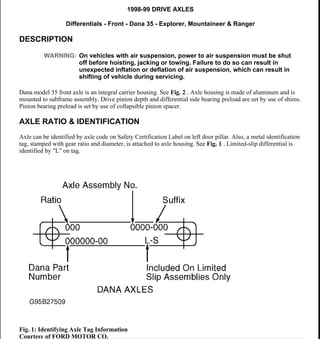
  • 1. 1998-99 DRIVE AXLES Differentials - Front - Dana 35 - Explorer, Mountaineer & Ranger DESCRIPTION Dana model 35 front axle is an integral carrier housing. See Fig. 2 . Axle housing is made of aluminum and is mounted to subframe assembly. Drive pinion depth and differential side bearing preload are set by use of shims. Pinion bearing preload is set by use of collapsible pinion spacer. AXLE RATIO & IDENTIFICATION Axle can be identified by axle code on Safety Certification Label on left door pillar. Also, a metal identification tag, stamped with gear ratio and diameter, is attached to axle housing. See Fig. 1 . Limited-slip differential is identified by "L" on tag. Fig. 1: Identifying Axle Tag Information Courtesy of FORD MOTOR CO. WARNING: On vehicles with air suspension, power to air suspension must be shut off before hoisting, jacking or towing. Failure to do so can result in unexpected inflation or deflation of air suspension, which can result in shifting of vehicle during servicing. 1999 Ford Explorer 1998-99 DRIVE AXLES Differentials - Front - Dana 35 - Explorer, Mountaineer & Ranger 1999 Ford Explorer 1998-99 DRIVE AXLES Differentials - Front - Dana 35 - Explorer, Mountaineer & Ranger Helpmelearn November-17-07 10:45:31 AM Page 1 © 2005 Mitchell Repair Information Company, LLC. Helpmelearn November-17-07 10:45:34 AM Page 1 © 2005 Mitchell Repair Information Company, LLC.
  • 2. Fig. 2: Exploded View Of Front Axle Housing Assembly (Typical) Courtesy of FORD MOTOR CO. LUBRICATION Capacity is 3.25 Pts. (1.54L) of Motorcraft SAE 80W90 Thermally Stable 4X4 Axle Lubricant (XL-80W90- QL). Capacities listed are approximate. Fill differential until fluid level is about 1/4" below bottom of filler plug hole. TROUBLE SHOOTING REMOVAL & INSTALLATION NOTE: See appropriate table in TROUBLE SHOOTING article in GENERAL INFORMATION. WARNING: On vehicles with air suspension, power to air suspension must be shut off before hoisting, jacking or towing. Failure to do so can result in unexpected inflation or deflation of air suspension, which can result in shifting of vehicle during servicing. 1999 Ford Explorer 1998-99 DRIVE AXLES Differentials - Front - Dana 35 - Explorer, Mountaineer & Ranger Helpmelearn November-17-07 10:45:31 AM Page 2 © 2005 Mitchell Repair Information Company, LLC.
  • 3. AXLE SHAFT, BEARING & OIL SEAL Removal Remove right axle shaft. See 4WD AXLE SHAFTS - FRONT - EXPLORER, MOUNTAINEER & RANGER article. Remove axle from axle housing. Using Converter Seal Remover (T94P-77001-BH) and slide hammer, remove axle tube seal. Using Bearing Remover (T94P-77001-KH) and slide hammer, remove axle tube bearing. Installation 1. Ensure bearing bore is clean and undamaged. Using Bearing Installer (T95T-1175-D) and Driver Handle (T80T-4000-W), install bearing in axle tube, .88" (44.5 mm) below outer lip of axle tube. Coat lip of seal with multipurpose grease. Using Seal Installer (T95T-3010-A) and Driver Handle (T80T-4000-W), install axle tube seal. 2. To complete installation, reverse removal procedure. Tighten all nuts and bolts or specification. See TORQUE SPECIFICATIONS . Fill differential with proper lubricant until fluid level is about 1/4" below bottom of filler plug hole. See LUBRICATION . AXLE HOUSING ASSEMBLY Removal & Installation 1. Raise and support vehicle. Remove both front axle shafts. See 4WD AXLE SHAFTS - FRONT - EXPLORER, MOUNTAINEER & RANGER article. Scribe alignment marks on drive shaft and pinion flange for installation reference. Remove driveshaft-to-pinion flange bolts, and wire drive shaft aside. 2. Disconnect axle housing vent hose. Using a suitable jack, support axle housing, and secure axle housing to jack. Remove 3 front axle housing-to-frame nuts and bolts. Lower floor jack, and remove axle housing assembly. 3. To install, reverse removal procedure. Tighten all nuts and bolts to specification. See TORQUE SPECIFICATIONS . Fill differential with proper lubricant until fluid level is about 1/4" below bottom of filler plug hole. See LUBRICATION . PINION FLANGE & OIL SEAL Removal 1. Raise and support vehicle. Scribe alignment marks on drive shaft and pinion flange for installation reference. Remove driveshaft-to-pinion flange bolts, and wire drive shaft aside. Using an INCH-lb. torque wrench, measure and record torque required to rotate pinion through several revolutions. 2. Hold pinion flange and remove pinion nut. Scribe index marks on pinion flange and pinion stem for installation reference. Remove pinion flange. Using Converter Seal Remover (T94P-77001-BH) and slide hammer, remove pinion seal. NOTE: Pinion flange and oil seal replacement affects bearing preload. Preload must be carefully reset during reassembly. 1999 Ford Explorer 1998-99 DRIVE AXLES Differentials - Front - Dana 35 - Explorer, Mountaineer & Ranger Helpmelearn November-17-07 10:45:31 AM Page 3 © 2005 Mitchell Repair Information Company, LLC.
  • 4. Installation 1. Ensure pinion shaft splines are free of burrs. Remove burrs with fine crocus cloth if necessary. Lubricate area between oil seal lip. Using Pinion Oil Seal Replacer (T79P-4676-A), install oil seal into axle housing. 2. Align marks on pinion flange and pinion stem. Apply a small amount of lubricant to pinion flange splines. Install pinion flange and NEW pinion nut. Hold pinion flange, and gradually tighten nut while rotating pinion. 3. Check pinion bearing preload often, until correct preload is obtained. DO NOT back off pinion nut to reduce preload. See DIFFERENTIAL SPECIFICATIONS . Connect rear end of drive shaft to pinion flange, aligning scribed marks. 4. Apply locking compound to drive shaft bolt threads and tighten bolts to specification. See TORQUE SPECIFICATIONS . Fill differential with proper lubricant until fluid level is about 1/4" below bottom of filler plug hole. See LUBRICATION . OVERHAUL DISASSEMBLY 1. Remove axle housing. See AXLE HOUSING ASSEMBLY under REMOVAL & INSTALLATION. Mount axle housing in Holding Fixture (T57L-500-B) using Adapters (T90T-4000-A) and Spacer (T80T- 4000-B2). Remove housing cover, and drain differential fluid. 2. Remove axle shaft from axle housing. Using Converter Seal Remover (T94P-77001-BH) and slide hammer, remove right and left axle tube seal. Using Bearing Remover (T94P-77001-KH) and slide hammer, remove right and left axle tube bearings (if necessary). 3. Note matched numbers or letters on differential bearing caps and carrier for reassembly reference. Remove bearing caps. Install Housing Spreader Adapter Set (T90T-4000-A) and Differential Housing Spreader (TOOL-4000-E). See Fig. 3 . Mount dial indicator onto axle housing to measure amount of spread. 4. Spread axle housing to .020" (.51 mm). Remove dial indicator. Carefully pry differential assembly out of housing. Remove spreader immediately so housing does not permanently distort. Remove and tag side bearing races to indicate from which side of carrier they were removed. 5. Turn nose of axle housing up. Using an INCH lbs. torque wrench, measure and record pinion bearing NOTE: If oil seal becomes cocked during installation, remove seal and install NEW oil seal. NOTE: If desired preload is exceeded, a NEW collapsible spacer must be installed. Tighten nut to obtain proper preload. CAUTION: DO NOT spread carrier housing more than .030" (.76 mm), since permanent damage to housing could result. 1999 Ford Explorer 1998-99 DRIVE AXLES Differentials - Front - Dana 35 - Explorer, Mountaineer & Ranger Helpmelearn November-17-07 10:45:31 AM Page 4 © 2005 Mitchell Repair Information Company, LLC.
  • 5. preload. Hold pinion flange and remove pinion nut. Scribe index marks on pinion flange and pinion stem for installation reference. Remove pinion flange. Using Converter Seal Remover (T94P-77001-BH) and slide hammer, remove pinion seal. 6. Remove drive pinion by tapping with soft-face mallet. Remove outer pinion bearing and oil slinger. Drive out inner and outer drive pinion bearing race using Pinion Bearing Race Remover (T86T-4628-BH) and Driver Handle (T80T-4000-W). Press pinion bearing off pinion. Measure and record inner pinion bearing shim thickness. 7. Place differential case into vise, with rags underneath to protect ring gear. Remove and discard ring gear bolts. Tap ring gear with soft-face mallet to remove ring gear from case. Using drift and hammer, drive out pinion shaft lock pin. Remove pinion shaft. 8. Rotate side gears until pinion gears are aligned with case opening. Remove pinion gears and thrust washers. Remove side gears with thrust washers. Using universal bearing remover, remove inner pinion bearing and oil slinger from drive pinion. Fig. 3: Spreading Axle Housing Courtesy of FORD MOTOR CO. CLEANING & INSPECTION 1999 Ford Explorer 1998-99 DRIVE AXLES Differentials - Front - Dana 35 - Explorer, Mountaineer & Ranger Helpmelearn November-17-07 10:45:31 AM Page 5 © 2005 Mitchell Repair Information Company, LLC.
  • 6. 1. Clean all components in solvent. Allow bearings to air dry. Inspect all machined surfaces for smoothness or raised edges. Inspect all gear teeth for wear or chipping, and replace as necessary. 2. Check all bearings and races for nicks, roller end wear, grooves or damage. Replace as needed. Check pinion flange for wear in sealing area and replace as necessary. 3. Check differential pinion shaft, pinion gears, side gears and thrust washers for wear or damage. Replace all defective parts. Replace pinion gear and ring gear as a set. REASSEMBLY 1. Install thurst washers onto differential side gears. Install differential side greas into differential housing. Install trurst washer and pinion gear into differential case. Install pinion shaft. Install pinion shaft roll pin. 2. Using Pinion Bearing Cup Replacer (T67P-4616-A), install pinion bearing cups. If using old ring and pinion gear set, go to next step. If using new ring and pinion gear set, go to step 8 . 3. Apply a light film of oil to pinion bearing. Assemble Pinion Depth Gauge (T79P-4020-A). Install aligning adapter, gauge disc and screw. Place rear pinion bearing over aligning adapter and into bearing cup of carrier housing. See Fig. 4 . 4. Install front pinion bearing into front bearing cup. Place handle onto screw and tighten to 20 INCH lbs. (2.25 N.m). See Fig. 5 . Ensure pinion depth measuring tool is properly installed and tightened. 5. Rotate gauge block several times to seat bearings. Rotational torque on gauge block assembly should be 20 INCH lbs. (2.25 N.m) with new bearings. Final position of gauge block should be 45 degrees above axle shaft center line. See Fig. 6 . 6. Clean differential bearing bores thoroughly, and install gauge tube. Tighten differential bearing cap bolts to specification. See TORQUE SPECIFICATIONS . Use flat pinion shims as a gauge for shim selection. Hold gauge block in proper position, and measure clearance between gauge block and tube. 7. Correct shim selection is accomplished when a slight drag is felt as shim is drawn between gauge block and tube. Shims are available in various thicknesses. Install correct shim on pinion for reassembly. Pinion bearings must be installed in the same location as during pinion depth measurement. Remove measuring equipment and go to step 9 . 8. Notice the plus (+), minus (-) or zero (0) etching on both old and new pinion and adjust thickness of new shim according to charts in illustration. See Fig. 7 . Go to next step. 9. Place pinion shim previously determine on pinion shaft and press on inner pinion bearing. Place NEW collapsible spacer on pinion shaft. Install outer pinion bearing and oil slinger in axle housing. Using Pinion Oil Seal Replacer (T79P-4676-A), install oil seal into axle housing. 10. Position pinion gear in axle housing. Align marks on pinion flange and pinion stem. Apply a small amount of lubricant to pinion flange splines. Install pinion flange and NEW pinion nut. Hold pinion flange, and gradually tighten nut while rotating pinion. NOTE: If oil seal becomes cocked during installation, remove seal and install NEW oil seal. NOTE: If desired preload is exceeded, a NEW collapsible spacer must be installed. Tighten nut to obtain proper preload. 1999 Ford Explorer 1998-99 DRIVE AXLES Differentials - Front - Dana 35 - Explorer, Mountaineer & Ranger Helpmelearn November-17-07 10:45:31 AM Page 6 © 2005 Mitchell Repair Information Company, LLC.
  • 7. 11. Check pinion bearing preload often, until correct preload is obtained. DO NOT back off pinion nut to reduce preload. See DIFFERENTIAL SPECIFICATIONS . Remove differential bearing and install Right Master Bearing (T93P-4222-B) and Left Master Bearing (T93P-4222-A) on differential housing. 12. Insert differential and master bearings into axle housing. Position dial indicator to outside mounting hole. Position indicator tip on machined surface of differential case flange. Adjust dial indicator to measure full travel. Push differential case left and right as far as possible. Measure total end play and record on Line-A of differential bearing shim selection procedure work sheet. See Fig. 9 . 13. Remove differential case from carrier to install ring gear. Ensure ring is free of any nicks or burrs. Press ring gear onto case, and tighten bolts to correct torque. See TORQUE SPECIFICATIONS . Install differential case with master bearings into axle housing. 14. With dial indicator in place, push ring gear to mesh with pinion gear. Rock ring gear to allow full mesh with pinion gear. Zero dial indicator. Move ring gear away from pinion gear as much as possible. Record measurement on Line-B of differential bearing shim selection procedure work sheet. Remove differential from housing, and remove master bearing from carrier assembly. 15. Identify and mark right and left bearing for installation reference. Clamp Bearing Preload Tool (T93P- 4220-AR) base in a soft-jaw vise. Keep bearing mounting surface above vise jaws. Position bearing assembly on bearing preload tool base, and tighten tool bolt to 20 INCH lbs. (2.3 N.m). See Fig. 8 . 16. Invert preload tool and clamp bolt head in vise. Position depth micrometer over top of bearing. With depth micrometer positioned on bearing cone, measure height of each individual bearing assembly. Measure distance from bearing cone to bearing preload tool disc. Record both bearing measurements on Line-D on differential bearing shim selection procedure work sheet. 17. Select appropriate bearing shims using differential bearing shim selection procedure work sheet. See Fig. 9 . For correct shim, see DIFFERENTIAL SHIM SIZE table. 18. Remove master bearing from carrier, and press appropriate differential bearing on appropriate side of differential case. Tighten housing spreader so dial indicator reads .030" (.762 mm). Install selected shims. 19. Install differential assembly in axle housing. Install and tighten bearing caps to specification with housing spreader still installed. See TORQUE SPECIFICATIONS . Loosen and remove spreader. Move dial indicator base and mount in line with ring gear. 20. Mount dial indicator, and zero indicator on any ring gear drive tooth. See Fig. 10 . Turn ring gear without turning pinion gear to measure backlash. Preferred backlash is .005-008" (.127-.203 mm). 21. If backlash is not to specification, adjust backlash by increasing thickness of one shim and decreasing thickness of other shim by same amount. See RING GEAR BACKLASH-TO-SHIM THICKNESS CONVERSION table. See Fig. 11 . 22. To complete assembly, reverse disassembly procedure. Tighten all nuts and bolts to specification. See TORQUE SPECIFICATIONS . Fill differential with proper lubricant until fluid level is about 1/4" below bottom of filler plug hole. See LUBRICATION . DIFFERENTIAL SHIM SIZE Color No. Of Stripes Shim Thickness - In. (mm) Red 1 .2410-.2415 (6.121-6.134) Red 2 .2430-.2435 (6.172-6.185) Orange 1 .2450-.2455 (6.223-6.236) Orange 2 .2470-.2475 (6.274-6.287) 1999 Ford Explorer 1998-99 DRIVE AXLES Differentials - Front - Dana 35 - Explorer, Mountaineer & Ranger Helpmelearn November-17-07 10:45:31 AM Page 7 © 2005 Mitchell Repair Information Company, LLC.
  • 8. RING GEAR BACKLASH-TO-SHIM THICKNESS CONVERSION Orange 3 .2490-.2495 (6.325-6.337) Orange 4 .2510-.2515 (6.375-6.388) Orange 5 .2530-.2535 (6.426-6.439) Yellow 1 .2550-.2555 (6.477-6.490) Yellow 2 .2570-.2575 (6.528-6.541) Yellow 3 .2590-.2595 (6.579-6.591) Yellow 4 .2610-.2615 (6.629-6.642) Yellow 5 .2630-.2635 (6.680-6.693) White 1 .2650-.2655 (6.731-6.744) White 2 .2670-.2675 (6.782-6.795) White 3 .2690-.2695 (6.833-6.845) White 4 .2710-.2715 (6.883-6.896) White 5 .2730-.2735 (6.934-6.947) Green 1 .2750-.2755 (6.985-6.998) Green 2 .2770-.2775 (7.036-7.049) Green 3 .2790-.2795 (7.087-7.099) Green 4 .2810-.2815 (7.137-7.150) Green 5 .2830-.2835 (7.188-7.201) Pink 1 .2850-.2855 (7.239-7.252) Pink 2 .2870-.2875 (7.290-7.303) Pink 3 .2890-.2895 (7.341-7.353) Pink 4 .2910-.2915 (7.391-7.404) Pink 5 .2930-.2935 (7.442-7.455) Blue 2 .2970-.2975 (7.544-7.557) Blue 3 .2990-.2995 (7.595-7.607) Blue 4 .3010-.3015 (7.645-7.658) Blue 5 .3030-.3035 (7.696-7.709) Gray 1 .3050-.3055 (7.747-7.760) Gray 2 .3070-.3075 (7.798-7.811) Required Change In Backlash - In. (mm) Required Change In Shim Thickness - In. (mm) .001 (.03) .002 (.05) .002 (.05) .002 (.05) .003 (.08) .004 (.10) .004 (.10) .006 (.15) .005 (.13) .006 (.15) .006 (.15) .008 (.20) .007 (.18) .010 (.25) .008 (.20) .010 (.25) .009 (.23) .012 (.30) 1999 Ford Explorer 1998-99 DRIVE AXLES Differentials - Front - Dana 35 - Explorer, Mountaineer & Ranger Helpmelearn November-17-07 10:45:31 AM Page 8 © 2005 Mitchell Repair Information Company, LLC.
  • 9. Fig. 4: Assembling Pinion Depth Gauge Courtesy of FORD MOTOR CO. .010 (.25) .014 (.36) .011 (.28) .014 (.36) .012 (.30) .016 (.41) .013 (.33) .018 (.46) .014 (.36) .018 (.46) .015 (.38) .020 (.51) 1999 Ford Explorer 1998-99 DRIVE AXLES Differentials - Front - Dana 35 - Explorer, Mountaineer & Ranger Helpmelearn November-17-07 10:45:31 AM Page 9 © 2005 Mitchell Repair Information Company, LLC.
  • 10. Fig. 5: Installing Pinion Depth Gauge Courtesy of FORD MOTOR CO. 1999 Ford Explorer 1998-99 DRIVE AXLES Differentials - Front - Dana 35 - Explorer, Mountaineer & Ranger Helpmelearn November-17-07 10:45:31 AM Page 10 © 2005 Mitchell Repair Information Company, LLC.
  • 11. Fig. 6: Final Position Of Pinion Depth Gauge Courtesy of FORD MOTOR CO. 1999 Ford Explorer 1998-99 DRIVE AXLES Differentials - Front - Dana 35 - Explorer, Mountaineer & Ranger Helpmelearn November-17-07 10:45:31 AM Page 11 © 2005 Mitchell Repair Information Company, LLC.
  • 12. Fig. 7: Pinion Depth Shim Adjustment Charts Courtesy of FORD MOTOR CO. 1999 Ford Explorer 1998-99 DRIVE AXLES Differentials - Front - Dana 35 - Explorer, Mountaineer & Ranger Helpmelearn November-17-07 10:45:31 AM Page 12 © 2005 Mitchell Repair Information Company, LLC.
  • 13. Fig. 8: Positioning Bearing Preload Tool Courtesy of FORD MOTOR CO. 1999 Ford Explorer 1998-99 DRIVE AXLES Differentials - Front - Dana 35 - Explorer, Mountaineer & Ranger Helpmelearn November-17-07 10:45:31 AM Page 13 © 2005 Mitchell Repair Information Company, LLC.
  • 14. Fig. 9: Differential Bearing Shim Selection Procedure Work Sheet Courtesy of FORD MOTOR CO. 1999 Ford Explorer 1998-99 DRIVE AXLES Differentials - Front - Dana 35 - Explorer, Mountaineer & Ranger Helpmelearn November-17-07 10:45:31 AM Page 14 © 2005 Mitchell Repair Information Company, LLC.
  • 15. Fig. 10: Checking Ring Gear Backlash Courtesy of FORD MOTOR CO. 1999 Ford Explorer 1998-99 DRIVE AXLES Differentials - Front - Dana 35 - Explorer, Mountaineer & Ranger Helpmelearn November-17-07 10:45:31 AM Page 15 © 2005 Mitchell Repair Information Company, LLC.
  • 16. Fig. 11: Adjusting Ring Gear Backlash Courtesy of FORD MOTOR CO. DIFFERENTIAL SPECIFICATIONS AXLE ASSEMBLY SPECIFICATIONS TORQUE SPECIFICATIONS TORQUE SPECIFICATIONS Application In. (mm) Ring Gear-To-Pinion Backlash (1) .005-.008 (.13-.20) INCH Lbs. (N.m) Drive Pinion Bearing Preload New Bearings 15-35 (1.7-4.0) Used Bearings 8-14 (.9-1.6) (1) Maximum backlash variation between 3 equally spaced check points is .003" (.08 mm). Application Ft. Lbs. (N.m) Drive Shaft Bolt 11-15 (15-20) 1999 Ford Explorer 1998-99 DRIVE AXLES Differentials - Front - Dana 35 - Explorer, Mountaineer & Ranger Helpmelearn November-17-07 10:45:31 AM Page 16 © 2005 Mitchell Repair Information Company, LLC.
  • 17. Front Axle Housing-To-Frame Bolt 45-59 (61-80) Housing Cover Bolt 20-25 (27-34) Ring Gear Bolt 70-89 (95-121) Side Bearing Cap Bolt 47-67 (64-91) Wheel Lug Nuts 100 (136) 1999 Ford Explorer 1998-99 DRIVE AXLES Differentials - Front - Dana 35 - Explorer, Mountaineer & Ranger Helpmelearn November-17-07 10:45:32 AM Page 17 © 2005 Mitchell Repair Information Company, LLC.
  • 18. 1997-99 DRIVE AXLES Differential - Front - 8.8" Ring Gear - Expedition, "F" Series Light Duty, Mountaineer & Navigator DESCRIPTION & OPERATION A half-shaft type front axle is used. Axle is of integral carrier housing, hypoid gear type. Drive pinion and ring gear bearing adjustments are all accomplished with shims. Power is transmitted through transfer case driveshaft to the drive pinion located in the axle housing. Drive pinion shaft is supported by 2 opposed tapered roller bearings. Power is transmitted from pinion gear through ring gear and differential pinion gears to axle shafts and wheels. On all models except 1999 Expedition and Navigator, a vacuum operated clutch engages front axle. 1999 Expedition and Navigator is an all wheel drive vehicle. Front axle is engaged at all time. See Fig. 1 or Fig. 2 . Fig. 1: Exploded View Of Front Axle Housing Assembly (Except 1999 Expedition & Navigator) Courtesy of FORD MOTOR CO. 1999 Ford Explorer 1997-99 DRIVE AXLES Differential - Front - 8.8" Ring Gear - Expedition, "F" Series Light Duty, Mountaineer & Navigator 1999 Ford Explorer 1997-99 DRIVE AXLES Differential - Front - 8.8" Ring Gear - Expedition, "F" Series Light Duty, Mountaineer & Navigator Helpmelearn November-17-07 10:46:09 AM Page 1 © 2005 Mitchell Repair Information Company, LLC. Helpmelearn November-17-07 10:46:12 AM Page 1 © 2005 Mitchell Repair Information Company, LLC.
  • 19. Fig. 2: Exploded View Of Front Axle Housing Assembly (1999 Expedition & Navigator) Courtesy of FORD MOTOR CO. AXLE RATIO & IDENTIFICATION Axle application can be determined through the axle code on the Safety Certification Label on left door pillar. Additionally, a metal identification tag stamped with gear ratio and diameter is secured to axle housing. See Fig. 3 . 1999 Ford Explorer 1997-99 DRIVE AXLES Differential - Front - 8.8" Ring Gear - Expedition, "F" Series Light Duty, Mountaineer & Navigator Helpmelearn November-17-07 10:46:09 AM Page 2 © 2005 Mitchell Repair Information Company, LLC.
  • 20. Fig. 3: Identifying Axle Identification Tag Courtesy of FORD MOTOR CO. LUBRICATION Capacity is 3.5-3.7 Pts. (1.8-2.0L) of Motorcraft SAE 75W90 Thermally Stable 4X4 Axle Lubricant (XY- 75W90-QL). Capacities listed are approximate. Fill differential until fluid level is about 1/4" below bottom of filler plug hole. TROUBLE SHOOTING REMOVAL & INSTALLATION AXLE HOUSING ASSEMBLY Removal & Installation NOTE: See appropriate table in TROUBLE SHOOTING article in GENERAL INFORMATION. WARNING: On vehicles with air suspension, power to air suspension must be shut off before hoisting, jacking or towing. Failure to do so can result in unexpected inflation or deflation of air suspension, which can result in shifting of vehicle during servicing. NOTE: DO NOT allow drive shaft to hang unsupported. 1999 Ford Explorer 1997-99 DRIVE AXLES Differential - Front - 8.8" Ring Gear - Expedition, "F" Series Light Duty, Mountaineer & Navigator Helpmelearn November-17-07 10:46:09 AM Page 3 © 2005 Mitchell Repair Information Company, LLC.
  • 21. 1. Raise and support vehicle. Mark pinion yoke and drive shaft alignment for reassembly reference. Disconnect drive shaft from yoke, and wire aside. Remove axle shaft-to-stub axle retaining bolts and wire aside (both sides). Disconnect vent tube. Disconnect front axle actuator motor vacuum line (if equipped). 2. Using a suitable jack, support axle housing assembly and secure axle housing to jack. Remove axle housing support bracket. Remove axle housing retaining bolts. To install, reverse removal procedure. Tighten bolts to specification. See TORQUE SPECIFICATIONS table. OVERHAUL (EXCEPT 1999 EXPEDITION & NAVIGATOR) DISASSEMBLY 1. Remove axle housing. See AXLE HOUSING ASSEMBLY under REMOVAL & INSTALLATION. Drain differential fluid. Remove housing cover. Mount axle housing in Holding Fixture (T57L-500-B) using Adapters (T90T-4000-A) and Spacer (T80T-4000-B2). 2. Pull back clutch boot and remove snap ring. Remove front axle actuator motor. Remove axle housing retaining bolts and remove assembly. Remove cluster gear thrust washer. Remove front axle cluster gear. Lift front axle shift lever and remove gear selector. Remove shift lever and shift fork by removing roll pin. 3. Remove left stub axle retaining clip (inside differential assembly). Remove left stub axle. Install Housing Spreader Adapter Set (T90T-4000-A) and Differential Housing Spreader (TOOL-4000-E). See Fig. 4 . Mount dial indicator on axle housing to measure amount of spread. 4. Spread axle housing to .030" (.76 mm). Remove dial indicator. Mark bearing cap for installation reference. Remove bearing cap retaining bolts and remove bearing caps. Carefully pry differential assembly out of housing. Remove spreader immediately so housing does not permanently distort. Remove and tag side bearing races to indicate from which side of carrier they were removed. 5. Turn nose of axle housing up. Using an INCH lbs. torque wrench, measure and record pinion bearing preload. Hold pinion flange and remove pinion nut. Scribe index marks on pinion flange and pinion stem for installation reference. Remove pinion flange. Using Converter Seal Remover (T94P-77001-BH) and slide hammer, remove pinion seal. 6. Remove drive pinion by tapping with soft-faced mallet. Remove outer pinion bearing and oil slinger. Using Puller Tool (T77F-1102-A) and Slide Hammer (T50T-100-A), remove inner bearing race. If necessary, remove oil baffle. Remove pinion outer bearing race. Press pinion bearing off pinion. Measure and record inner pinion bearing shim thickness. 7. Place differential case in vise, with rags underneath to protect ring gear. Remove ring gear bolts. Tap ring gear with soft-face mallet to remove ring gear from case. Remove pinion shaft lock bolt. Remove pinion WARNING: On vehicles with air suspension, power to air suspension must be shut off before hoisting, jacking or towing. Failure to do so can result in unexpected inflation or deflation of air suspension, which can result in shifting of vehicle during servicing. CAUTION: DO NOT spread axle housing more than .030" (.76 mm); permanent damage to housing could result. 1999 Ford Explorer 1997-99 DRIVE AXLES Differential - Front - 8.8" Ring Gear - Expedition, "F" Series Light Duty, Mountaineer & Navigator Helpmelearn November-17-07 10:46:09 AM Page 4 © 2005 Mitchell Repair Information Company, LLC.
  • 22. shaft. 8. Rotate side gears until pinion gears are aligned with case opening. Remove pinion gears and thrust washers. Remove side gears with thrust washers. Remove differential case side bearings. Fig. 4: Spreading Axle Housing Courtesy of FORD MOTOR CO. CLEANING & INSPECTION 1. Clean all components in solvent. Allow bearings to air dry. Inspect all machined surfaces for smoothness or raised edges. Inspect all gear teeth for wear or chipping and replace as necessary. 2. Check all bearings and races for nicks, roller end wear, grooves or damage. Replace as needed. Check pinion flange for wear in sealing area and replace as necessary. 3. Check differential pinion shaft, pinion gears, side gears and thrust washers for wear or damage. Replace all defective parts. Replace pinion gear and ring gear as a set. REASSEMBLY 1. Install thrust washers on differential side gears. Install differential side gears in differential housing. 1999 Ford Explorer 1997-99 DRIVE AXLES Differential - Front - 8.8" Ring Gear - Expedition, "F" Series Light Duty, Mountaineer & Navigator Helpmelearn November-17-07 10:46:09 AM Page 5 © 2005 Mitchell Repair Information Company, LLC.
  • 23. Install thrust washer and pinion gear in differential case. Install pinion shaft. Install pinion shaft lock bolt. 2. Install oil baffle. Using Pinion Bearing Cup Replacer (T53T-4621-C), install pinion bearing races. Apply a light film of oil on pinion bearings. 3. Assemble Pinion Depth Gauge (T79P-4020-A). Install aligning adapter, gauge disc and screw. Place rear pinion bearing over aligning adapter and in to bearing cup of carrier housing. See Fig. 5 . 4. Install front pinion bearing into front bearing cup. Place handle onto screw and tighten to 20 INCH lbs. (2.25 N.m). See Fig. 6 . Ensure pinion depth measuring tool is properly installed and tightened. 5. Rotate gauge block several times to seat bearings. Rotational torque on gauge block assembly should be 20 INCH lbs. (2.25 N.m) with new bearings. Final position of gauge block should be 45 degrees above axle shaft center line. See Fig. 7 . 6. Clean differential bearing bores thoroughly, and install gauge tube. Tighten differential bearing cap bolts to specification. See TORQUE SPECIFICATIONS . Use flat pinion shims as a gauge for shim selection. Hold gauge block in proper position, and measure clearance between gauge block and tube. 7. Correct shim selection is accomplished when a slight drag is felt as shim is drawn between gauge block and tube. Shims are available in various thicknesses. Install correct shim on pinion for reassembly. Pinion bearings must be installed in the same location as during pinion depth measurement. Remove measuring equipment. 8. Place pinion shim previously determine on pinion shaft and press on inner pinion bearing. Place NEW collapsible spacer on pinion shaft. Install outer pinion bearing and oil slinger in axle housing. Using Pinion Oil Seal Replacer (T79P-4676-A), install oil seal into axle housing. 9. Position pinion gear in axle housing. Align marks on pinion flange and pinion stem. Apply a small amount of lubricant to pinion flange splines. Install pinion flange and NEW pinion nut. Hold pinion flange, and gradually tighten nut while rotating pinion. 10. Check pinion bearing preload often, until correct preload is obtained. DO NOT back off pinion nut to reduce preload. See DIFFERENTIAL SPECIFICATIONS . Install Right Master Bearing (T93P-4222- B) and Left Master Bearing (T93P-4222-A) on differential housing. 11. Insert differential and master bearings into axle housing. Position dial indicator to outside mounting hole. Position indicator tip on machined surface of differential case flange. Adjust dial indicator to measure full travel. Push differential case left and right as far as possible. Measure total end play and record on Line-A of differential bearing shim selection procedure work sheet. See Fig. 9 . 12. Remove differential case from carrier to install ring gear. Ensure ring is free of any nicks or burrs. Press ring gear onto case, and tighten bolts to correct torque. See TORQUE SPECIFICATIONS . Install differential case with master bearings into axle housing. 13. With dial indicator in place, push ring gear to mesh with pinion gear. Rock ring gear to allow full mesh with pinion gear. Zero dial indicator. Move ring gear away from pinion gear as much as possible. Record measurement on Line-B of differential bearing shim selection procedure work sheet. Remove differential NOTE: If oil seal becomes cocked during installation, remove seal and install NEW oil seal. NOTE: If desired preload is exceeded, a NEW collapsible spacer must be installed. Tighten nut to obtain proper preload. 1999 Ford Explorer 1997-99 DRIVE AXLES Differential - Front - 8.8" Ring Gear - Expedition, "F" Series Light Duty, Mountaineer & Navigator Helpmelearn November-17-07 10:46:09 AM Page 6 © 2005 Mitchell Repair Information Company, LLC.
  • 24. from housing, and remove master bearing from carrier assembly. 14. Identify and mark right and left bearing for installation reference. Clamp Bearing Preload Tool (T93P- 4220-AR) base in a soft-jaw vise. Keep bearing mounting surface above vise jaws. Position bearing assembly on bearing preload tool base, and tighten tool bolt to 20 INCH lbs. (2.3 N.m). See Fig. 8 . 15. Invert preload tool and clamp bolt head in vise. Position depth micrometer over top of bearing. With depth micrometer positioned on bearing cone, measure height of each individual bearing assembly. Measure distance from bearing cone to bearing preload tool disc. Record both bearing measurements on Line-D on differential bearing shim selection procedure work sheet. 16. Select appropriate bearing shims using differential bearing shim selection procedure work sheet. See Fig. 9 . For correct shim, see DIFFERENTIAL SHIM SIZE table. 17. Remove master bearing from carrier, and press appropriate differential bearing on appropriate side of differential case. Tighten housing spreader so dial indicator reads .030" (.76 mm). Install selected shims. 18. Install differential assembly in axle housing. Install and tighten bearing caps to correct torque with housing spreader still installed. See TORQUE SPECIFICATIONS . Loosen and remove spreader. Move dial indicator base and mount in line with ring gear. 19. Mount dial indicator, and zero on any ring gear drive tooth. See Fig. 10 . Turn ring gear without turning pinion gear to measure backlash. Preferred backlash is .008-.013" (.203-.330 mm). 20. If backlash is not to specification, adjust backlash by increasing thickness of one shim and decreasing thickness of other shim by same amount. See RING GEAR BACKLASH-TO-SHIM THICKNESS CONVERSION table. See Fig. 11 . 21. Instal NEW "O" ring on shift lever. Position shift fork in axle housing. Lubricate "O" ring, and install shift lever. Install roll pin until flush with top of shift fork. Lift shift lever and install selector gear. Install front axle cluster gear and cluster gear thrust washer. 22. Using Ford Black Silicone Rubber (F4AZ-19562-B), fill grove groove in axle housing and install front axle tube. Tighten axle tube retaining bolts to specification. See TORQUE SPECIFICATIONS . 23. Install left stub axle seal. Install left stub axle and new retaining clip (inside differential assembly). Install front axle actuator motor. Using a vacuum pump, verify front axle actuator motor does not leak down. Also, ensure front axle clutch is engaging completely. 24. To complete assembly, reverse disassembly procedure. Tighten all nuts and bolts to specifications. See TORQUE SPECIFICATIONS . Fill differential with proper lubricant until fluid level is about 1/4" below bottom of filler plug hole. See LUBRICATION . DIFFERENTIAL SHIM SIZE Color No. Of Stripes Shim Thickness In. (mm) Red 1 .2410-.2415 (6.121-6.134) Red 2 .2430-.2435 (6.172-6.185) Orange 1 .2450-.2455 (6.223-6.236) Orange 2 .2470-.2475 (6.274-6.287) Orange 3 .2490-.2495 (6.325-6.337) Orange 4 .2510-.2515 (6.375-6.388) Orange 5 .2530-.2535 (6.426-6.439) Yellow 1 .2550-.2555 (6.477-6.490) Yellow 2 .2570-.2575 (6.528-6.541) 1999 Ford Explorer 1997-99 DRIVE AXLES Differential - Front - 8.8" Ring Gear - Expedition, "F" Series Light Duty, Mountaineer & Navigator Helpmelearn November-17-07 10:46:09 AM Page 7 © 2005 Mitchell Repair Information Company, LLC.
  • 25. RING GEAR BACKLASH-TO-SHIM THICKNESS CONVERSION Yellow 3 .2590-.2595 (6.579-6.591) Yellow 4 .2610-.2615 (6.629-6.642) Yellow 5 .2630-.2635 (6.680-6.693) White 1 .2650-.2655 (6.731-6.744) White 2 .2670-.2675 (6.782-6.795) White 3 .2690-.2695 (6.833-6.845) White 4 .2710-.2715 (6.883-6.896) White 5 .2730-.2735 (6.934-6.947) Green 1 .2750-.2755 (6.985-6.998) Green 2 .2770-.2775 (7.036-7.049) Green 3 .2790-.2795 (7.087-7.099) Green 4 .2810-.2815 (7.137-7.150) Green 5 .2830-.2835 (7.188-7.201) Pink 1 .2850-.2855 (7.239-7.252) Pink 2 .2870-.2875 (7.290-7.303) Pink 3 .2890-.2895 (7.341-7.353) Pink 4 .2910-.2915 (7.391-7.404) Pink 5 .2930-.2935 (7.442-7.455) Blue 2 .2970-.2975 (7.544-7.557) Blue 3 .2990-.2995 (7.595-7.607) Blue 4 .3010-.3015 (7.645-7.658) Blue 5 .3030-.3035 (7.696-7.709) Gray 1 .3050-.3055 (7.747-7.760) Gray 2 .3070-.3075 (7.798-7.811) Required Change In Backlash - In. (mm) Required Change In Shim Thickness - In. (mm) .001 (.03) .002 (.05) .002 (.05) .002 (.05) .003 (.08) .004 (.10) .004 (.10) .006 (.15) .005 (.13) .006 (.15) .006 (.15) .008 (.20) .007 (.18) .010 (.25) .008 (.20) .010 (.25) .009 (.23) .012 (.30) .010 (.25) .014 (.36) .011 (.28) .014 (.36) .012 (.30) .016 (.41) .013 (.33) .018 (.46) .014 (.36) .018 (.46) 1999 Ford Explorer 1997-99 DRIVE AXLES Differential - Front - 8.8" Ring Gear - Expedition, "F" Series Light Duty, Mountaineer & Navigator Helpmelearn November-17-07 10:46:09 AM Page 8 © 2005 Mitchell Repair Information Company, LLC.
  • 26. Fig. 5: Assembling Pinion Depth Gauge Courtesy of FORD MOTOR CO. .015 (.38) .020 (.51) 1999 Ford Explorer 1997-99 DRIVE AXLES Differential - Front - 8.8" Ring Gear - Expedition, "F" Series Light Duty, Mountaineer & Navigator Helpmelearn November-17-07 10:46:09 AM Page 9 © 2005 Mitchell Repair Information Company, LLC.
  • 27. Fig. 6: Installing Pinion Depth Gauge Courtesy of FORD MOTOR CO. 1999 Ford Explorer 1997-99 DRIVE AXLES Differential - Front - 8.8" Ring Gear - Expedition, "F" Series Light Duty, Mountaineer & Navigator Helpmelearn November-17-07 10:46:09 AM Page 10 © 2005 Mitchell Repair Information Company, LLC.
  • 28. Fig. 7: Final Position Of Pinion Depth Gauge Courtesy of FORD MOTOR CO. 1999 Ford Explorer 1997-99 DRIVE AXLES Differential - Front - 8.8" Ring Gear - Expedition, "F" Series Light Duty, Mountaineer & Navigator Helpmelearn November-17-07 10:46:09 AM Page 11 © 2005 Mitchell Repair Information Company, LLC.
  • 29. Fig. 8: Positioning Bearing Preload Tool Courtesy of FORD MOTOR CO. 1999 Ford Explorer 1997-99 DRIVE AXLES Differential - Front - 8.8" Ring Gear - Expedition, "F" Series Light Duty, Mountaineer & Navigator Helpmelearn November-17-07 10:46:09 AM Page 12 © 2005 Mitchell Repair Information Company, LLC.
  • 30. Fig. 9: Differential Bearing Shim Selection Procedure Work Sheet Courtesy of FORD MOTOR CO. 1999 Ford Explorer 1997-99 DRIVE AXLES Differential - Front - 8.8" Ring Gear - Expedition, "F" Series Light Duty, Mountaineer & Navigator Helpmelearn November-17-07 10:46:09 AM Page 13 © 2005 Mitchell Repair Information Company, LLC.
  • 31. Fig. 10: Checking Ring Gear Backlash Courtesy of FORD MOTOR CO. 1999 Ford Explorer 1997-99 DRIVE AXLES Differential - Front - 8.8" Ring Gear - Expedition, "F" Series Light Duty, Mountaineer & Navigator Helpmelearn November-17-07 10:46:09 AM Page 14 © 2005 Mitchell Repair Information Company, LLC.
  • 32. Fig. 11: Adjusting Ring Gear Backlash Courtesy of FORD MOTOR CO. OVERHAUL (1999 EXPEDITION & NAVIGATOR) DISASSEMBLY 1. Remove axle housing. See AXLE HOUSING ASSEMBLY under REMOVAL & INSTALLATION. Drain differential fluid. Remove housing cover. Mount axle housing in Holding Fixture (T57L-500-B) using Adapters (T90T-4000-A) and Spacer (T80T-4000-B2). 2. Remove axle housing retaining bolts and remove assembly. Remove coupler shaft selector gear. Remove front axle cluster gear. 3. Remove left stub axle retaining clip (inside differential assembly). Remove left stub axle. Install Housing Spreader Adapter Set (T90T-4000-A) and Differential Housing Spreader (TOOL-4000-E). See Fig. 4 . Mount dial indicator on axle housing to measure amount of spread. WARNING: On vehicles with air suspension, power to air suspension must be shut off before hoisting, jacking or towing. Failure to do so can result in unexpected inflation or deflation of air suspension, which can result in shifting of vehicle during servicing. 1999 Ford Explorer 1997-99 DRIVE AXLES Differential - Front - 8.8" Ring Gear - Expedition, "F" Series Light Duty, Mountaineer & Navigator Helpmelearn November-17-07 10:46:09 AM Page 15 © 2005 Mitchell Repair Information Company, LLC.
  • 33. 4. Spread axle housing to .030" (.76 mm). Remove dial indicator. Mark bearing cap for installation reference. Remove bearing cap retaining bolts and remove bearing caps. Carefully pry differential assembly out of housing. Remove spreader immediately so housing does not permanently distort. Remove and tag side bearing races to indicate from which side of carrier they were removed. 5. Turn nose of axle housing up. Using an INCH lbs. torque wrench, measure and record pinion bearing preload. Hold pinion flange and remove pinion nut. Scribe index marks on pinion flange and pinion stem for installation reference. Remove pinion flange. Using Converter Seal Remover (T94P-77001-BH) and slide hammer, remove pinion seal. 6. Remove drive pinion by tapping with soft-faced mallet. Remove outer pinion bearing and oil slinger. Using Puller Tool (T77F-1102-A) and Slide Hammer (T50T-100-A), remove inner bearing race. If necessary, remove oil baffle. Remove pinion outer bearing race. Press pinion bearing off pinion. Measure and record inner pinion bearing shim thickness. 7. Place differential case in vise, with rags underneath to protect ring gear. Remove ring gear bolts. Tap ring gear with soft-faced mallet to remove ring gear from case. Remove pinion shaft lock bolt. Remove pinion shaft. 8. Rotate side gears until pinion gears are aligned with case opening. Remove pinion gears and thrust washers. Remove side gears with thrust washers. Remove differential case side bearings. CLEANING & INSPECTION 1. Clean all components in solvent. Allow bearings to air dry. Inspect all machined surfaces for smoothness or raised edges. Inspect all gear teeth for wear or chipping and replace as necessary. 2. Check all bearings and races for nicks, roller end wear, grooves or damage. Replace as needed. Check pinion flange for wear in sealing area and replace as necessary. 3. Check differential pinion shaft, pinion gears, side gears and thrust washers for wear or damage. Replace all defective parts. Replace pinion gear and ring gear as a set. REASSEMBLY 1. Install thrust washers on differential side gears. Install differential side gears in differential housing. Install thrust washer and pinion gear in differential case. Install pinion shaft. Install pinion shaft lock bolt. 2. Install oil baffle. Using Pinion Bearing Cup Replacer (T53T-4621-C), install pinion bearing races. Apply a light film of oil on pinion bearings. 3. Assemble Pinion Depth Gauge (T79P-4020-A). Install aligning adapter, gauge disc and screw. Place rear pinion bearing over aligning adapter and into bearing cup of carrier housing. See Fig. 5 . 4. Install front pinion bearing into front bearing cup. Place handle onto screw and tighten to 20 INCH lbs. (2.25 N.m). See Fig. 6 . Ensure pinion depth measuring tool is properly installed and tightened. 5. Rotate gauge block several times to seat bearings. Rotational torque on gauge block assembly should be 20 INCH lbs. (2.25 N.m) with new bearings. Final position of gauge block should be 45 degrees above axle shaft center line. See Fig. 7 . 6. Clean differential bearing bores thoroughly, and install gauge tube. Tighten differential bearing cap bolts CAUTION: DO NOT spread axle housing more than .030" (.76 mm); permanent damage to housing could result. 1999 Ford Explorer 1997-99 DRIVE AXLES Differential - Front - 8.8" Ring Gear - Expedition, "F" Series Light Duty, Mountaineer & Navigator Helpmelearn November-17-07 10:46:09 AM Page 16 © 2005 Mitchell Repair Information Company, LLC.
  • 34. to specification. See TORQUE SPECIFICATIONS . Use flat pinion shims as a gauge for shim selection. Hold gauge block in proper position, and measure clearance between gauge block and tube. 7. Correct shim selection is accomplished when a slight drag is felt as shim is drawn between gauge block and tube. Shims are available in various thicknesses. Install correct shim on pinion for reassembly. Pinion bearings must be installed in the same location as during pinion depth measurement. Remove measuring equipment. 8. Place pinion shim previously determine on pinion shaft and press on inner pinion bearing. Place NEW collapsible spacer on pinion shaft. Install outer pinion bearing and oil slinger in axle housing. Using Pinion Oil Seal Replacer (T79P-4676-A), install oil seal into axle housing. 9. Position pinion gear in axle housing. Align marks on pinion flange and pinion stem. Apply a small amount of lubricant to pinion flange splines. Install pinion flange and NEW pinion nut. Hold pinion flange, and gradually tighten nut while rotating pinion. 10. Check pinion bearing preload often, until correct preload is obtained. DO NOT back off pinion nut to reduce preload. See DIFFERENTIAL SPECIFICATIONS . Install Right Master Bearing (T93P-4222- B) and Left Master Bearing (T93P-4222-A) on differential housing. 11. Insert differential and master bearings into axle housing. Position dial indicator to outside mounting hole. Position indicator tip on machined surface of differential case flange. Adjust dial indicator to measure full travel. Push differential case left and right as far as possible. Measure total end play and record on Line-A of differential bearing shim selection procedure work sheet. See Fig. 9 . 12. Remove differential case from carrier to install ring gear. Ensure ring is free of any nicks or burrs. Press ring gear onto case and tighten bolts to correct torque. See TORQUE SPECIFICATIONS . Install differential case with master bearings into axle housing. 13. With dial indicator in place, push ring gear to mesh with pinion gear. Rock ring gear to allow full mesh with pinion gear. Zero dial indicator. Move ring gear away from pinion gear as much as possible. Record measurement on Line-B of differential bearing shim selection procedure work sheet. Remove differential from housing, and remove master bearing from carrier assembly. 14. Identify and mark right and left bearing for installation reference. Clamp Bearing Preload Tool (T93P- 4220-AR) base in a soft-jaw vise. Keep bearing mounting surface above vise jaws. Position bearing assembly on bearing preload tool base, and tighten tool bolt to 20 INCH lbs. (2.3 N.m). See Fig. 8 . 15. Invert preload tool and clamp bolt head in vise. Position depth micrometer over top of bearing. With depth micrometer positioned on bearing cone, measure height of each individual bearing assembly. Measure distance from bearing cone to bearing preload tool disc. Record both bearing measurements on Line-D on differential bearing shim selection procedure work sheet. 16. Select appropriate bearing shims using differential bearing shim selection procedure work sheet. See Fig. 9 . For correct shim, see DIFFERENTIAL SHIM SIZE table. 17. Remove master bearing from carrier, and press appropriate differential bearing on appropriate side of NOTE: If oil seal becomes cocked during installation, remove seal and install NEW oil seal. NOTE: If desired preload is exceeded, a NEW collapsible spacer must be installed. Tighten nut to obtain proper preload. 1999 Ford Explorer 1997-99 DRIVE AXLES Differential - Front - 8.8" Ring Gear - Expedition, "F" Series Light Duty, Mountaineer & Navigator Helpmelearn November-17-07 10:46:10 AM Page 17 © 2005 Mitchell Repair Information Company, LLC.
  • 35. differential case. Tighten housing spreader so dial indicator reads .030" (.76 mm). Install selected shims. 18. Install differential assembly in axle housing. Install and tighten bearing caps to correct torque with housing spreader still installed. See TORQUE SPECIFICATIONS . Loosen and remove spreader. Move dial indicator base, and mount in line with ring gear. 19. Mount dial indicator, and zero on any ring gear drive tooth. See Fig. 10 . Turn ring gear without turning pinion gear to measure backlash. Preferred backlash is .012-.015" (.304-.381 mm). 20. If backlash is not to specification, adjust backlash by increasing thickness of one shim and decreasing thickness of other shim by same amount. See RING GEAR BACKLASH-TO-SHIM THICKNESS CONVERSION table. See Fig. 11 . 21. Install front axle cluster gear and coupler shaft selector gear. Using Ford Black Silicone Rubber (F4AZ- 19562-B), fill grove groove in axle housing and install front axle tube. Tighten axle tube retaining bolts to specification. See TORQUE SPECIFICATIONS . 22. Install left stub axle seal. Install left stub axle and NEW retaining clip (inside differential assembly). 23. To complete assembly, reverse disassembly procedure. Tighten all nuts and bolts to specifications. See TORQUE SPECIFICATIONS . Fill differential with proper lubricant until fluid level is about 1/4" below bottom of filler plug hole. See LUBRICATION . DIFFERENTIAL SPECIFICATIONS AXLE ASSEMBLY SPECIFICATIONS TORQUE SPECIFICATIONS TORQUE SPECIFICATIONS Application In. (mm) Differential Case Runout (Maximum) .003 (.076) Ring Gear Runout (Maximum) .004 (.10) Ring Gear-To-Pinion Backlash 1997-98 .008-.013 (.20-.33) 1999 (1) .008-.015 (.20-.38) INCH Lbs. (N.m) Drive Pinion Bearing Preload New Bearings 16-29 (1.8-3.3) Used Bearings 8-14 (.9-1.6) (1) Preferred backlash is .012-.015 (.30-.38) Application Ft. Lbs. (N.m) Axle Housing Mount Bolt 66 (89) Axle Shaft-To-Stub Axle Bolts 51-67 (69-91) Axle Tube Bolt 54 (73) Drain & Filler Plug 18 (24) Drive Shaft Bolts 70-95 (95-129) 1999 Ford Explorer 1997-99 DRIVE AXLES Differential - Front - 8.8" Ring Gear - Expedition, "F" Series Light Duty, Mountaineer & Navigator Helpmelearn November-17-07 10:46:10 AM Page 18 © 2005 Mitchell Repair Information Company, LLC.
  • 36. Housing Cover Bolt 24 (33) Pinion Shaft Lock Bolt 22 (30) Ring Gear Bolt 77 (104) Side Bearing Cap Bolt 77 (104) 1999 Ford Explorer 1997-99 DRIVE AXLES Differential - Front - 8.8" Ring Gear - Expedition, "F" Series Light Duty, Mountaineer & Navigator Helpmelearn November-17-07 10:46:10 AM Page 19 © 2005 Mitchell Repair Information Company, LLC.
  • 37. 1998-99 Drive Axles Differentials - Rear - 8.8" Ring Gear - Explorer, Mountaineer & Ranger DESCRIPTION Rear axle is a hypoid-design ring and pinion gear encased in an integral cast iron axle housing. A one-piece differential case contains a conventional 2-pinion differential assembly. To signal rear anti-lock brake system operation, rear axles use an exciter ring pressed on differential case behind ring gear, and a sensor mounted in axle housing. A space is provided between ring gear and exciter ring for measuring ring gear runout. AXLE RATIO & IDENTIFICATION A metal tag stamped with axle model, date of manufacture, ratio, ring gear diameter and assembly plant is attached to rear cover. Use information on tag to order replacement parts. See Fig. 1 . Vehicle axle application can also be determined by axle code on Safety Certification Label located on left door pillar. WARNING: On vehicles with air suspension, power to air suspension must be shut off before hoisting, jacking or towing. Failure to do so can result in unexpected inflation or deflation of air suspension, which can result in shifting of vehicle during servicing. NOTE: If rear axle is a Traction-Lok version, a "L" will be displayed with the ratio. For example, a Traction-Lok axle ratio would be displayed as 3L45. 1999 Ford Explorer 1998-99 Drive Axles Differentials - Rear - 8.8" Ring Gear - Explorer, Mountaineer & Ranger 1999 Ford Explorer 1998-99 Drive Axles Differentials - Rear - 8.8" Ring Gear - Explorer, Mountaineer & Ranger Helpmelearn November-17-07 10:46:51 AM Page 1 © 2005 Mitchell Repair Information Company, LLC. Helpmelearn November-17-07 10:46:54 AM Page 1 © 2005 Mitchell Repair Information Company, LLC.
  • 38. Fig. 1: Identifying Rear Axle Tag Courtesy of FORD MOTOR CO. LUBRICATION RANGER Capacity on vehicles without Traction-Lok differential is 5.1-5.3 Pts. (2.4-2.5L) of Motorcraft SAE 80W90 Thermally Stable Rear Axle Lubricant (XY-80W90-QL). Capacity on vehicles with Traction-Lok differential is 4.6-5.1 Pts. (2.2-2.4L) of Thermally Stable Rear Axle Lubricant (XY-80W90-QL), plus an additional 4 ozs. of Friction Modifier (C8AZ-19B546-A). Capacities listed are approximate. Fill differential until fluid level is about 1/4" below bottom of filler plug hole. EXPLORER & MOUNTAINEER (4.0L) Capacity on vehicles without Traction-Lok differential is 5.5-5.8 Pts. (2.6-2.7L) of Motorcraft SAE 80W90 Thermally Stable Rear Axle Lubricant (XY-80W90-QL). Capacity on vehicles with Traction-Lok differential is 5.5-5.8 Pts. (2.6-2.7L) of Motorcraft SAE 75W145 High Performance Synthetic Rear Axle Lubricant (F1TZ- 19580-B), plus an additional 4 ozs. of Friction Modifier (C8AZ-19B546-A). Capacities listed are approximate. CAUTION: On models with Traction-Lok differential, add an additional 4 ozs. of Friction Modifier (C8AZ-19B546-A). Friction modifier must be added to prevent damage to differential. CAUTION: On models with Traction-Lok differential, add an additional 4 ozs. of Friction Modifier (C8AZ-19B546-A). Friction modifier must be added to prevent damage to differential. 1999 Ford Explorer 1998-99 Drive Axles Differentials - Rear - 8.8" Ring Gear - Explorer, Mountaineer & Ranger Helpmelearn November-17-07 10:46:51 AM Page 2 © 2005 Mitchell Repair Information Company, LLC.
  • 39. Fill differential until fluid level is about 1/4" below bottom of filler plug hole. EXPLORER & MOUNTAINEER (5.0L) Capacity is 5.5-5.8 Pts. (2.6-2.7L) of Motorcraft SAE 75W145 High Performance Synthetic Rear Axle Lubricant (F1TZ-19580-B), plus an additional 4 ozs. of Friction Modifier (C8AZ-19B546-A). Capacities listed are approximate. Fill differential until fluid level is about 1/4" below bottom of filler plug hole. TROUBLE SHOOTING REMOVAL & INSTALLATION AXLE SHAFT & BEARING Removal (Explorer & Mountaineer) 1. Raise and support vehicle. Remove wheel assemblies. Remove rear brake caliper retaining bolts, and wire caliper aside. Remove rear brake rotor. Remove housing cover, and drain lubricant. 2. Remove differential pinion shaft lock bolt and remove pinion shaft. See Fig. 2 . Push axle shaft inward and remove "C" locks. Remove axle shaft, being careful not to cut axle seal. Using a slide hammer and puller, remove bearing and oil seal as a unit. NOTE: See appropriate table in TROUBLE SHOOTING article in GENERAL INFORMATION. WARNING: On vehicles with air suspension, power to air suspension MUST be shut off before hoisting, jacking or towing. Failure to do so can result in unexpected inflation or deflation of air suspension, which can result in shifting of vehicle during these operations. CAUTION: DO NOT damage "O" ring in axle shaft groove under "C" lock. 1999 Ford Explorer 1998-99 Drive Axles Differentials - Rear - 8.8" Ring Gear - Explorer, Mountaineer & Ranger Helpmelearn November-17-07 10:46:51 AM Page 3 © 2005 Mitchell Repair Information Company, LLC.
  • 40. Fig. 2: Exploded View Of Axle Assembly (Typical) Courtesy of FORD MOTOR CO. Installation 1. Lubricate bearing with rear axle lubricant. Using a driver, install bearing. Install oil seal. If seal becomes cocked during installation, remove seal and replace with a NEW one. 2. Carefully insert axle in housing to avoid damaging oil seal. Install "C" locks, and push shafts outward to seat locks in counterbore of differential side gears. 3. Install pinion gears and thrust washers (if removed). Turn gear assembly to align pinion gear and thrust washer bores with pinion shaft holes on case. Install pinion shaft. Apply Loctite to lock bolt and tighten to specification. See TORQUE SPECIFICATIONS . 4. Clean gasket mating surfaces and apply 1/8 - 3/16" wide bead of silicone sealant on axle housing cover. Install housing cover. Tighten cover bolts to specification in a crisscross pattern. See TORQUE SPECIFICATIONS . Fill differential until fluid level is about 1/4" below bottom of filler plug hole. To complete installation, reverse removal procedures. Removal (Ranger) 1. Raise and support vehicle. Remove rear wheel assemblies and brake drums. Remove housing cover, and drain lubricant. Remove differential pinion shaft lock bolt and remove pinion shaft. See Fig. 2 . Push axle CAUTION: DO NOT damage "O" ring in axle shaft groove under "C" lock. 1999 Ford Explorer 1998-99 Drive Axles Differentials - Rear - 8.8" Ring Gear - Explorer, Mountaineer & Ranger Helpmelearn November-17-07 10:46:51 AM Page 4 © 2005 Mitchell Repair Information Company, LLC.
  • 41. shaft inward and remove "C" locks. 2. Remove axle shaft, being careful not to cut axle seal. Using a slide hammer and puller, remove bearing and oil seal as a unit. Installation 1. Lubricate bearing with rear axle lubricant. Using a driver, install bearing. Install oil seal. If seal becomes cocked during installation, remove seal and replace with a new one. 2. Carefully insert axle in housing to avoid damaging oil seal. Install "C" locks, and push shafts outward to seat locks in counterbore of differential side gears. 3. Install pinion gears and thrust washers (if removed). Turn gear assembly to align pinion gear and thrust washer bores with pinion shaft holes on case. Install pinion shaft. Apply Loctite to lock bolt and tighten to specification. See TORQUE SPECIFICATIONS . 4. Clean gasket mating surfaces and apply 1/8 - 3/16" wide bead of silicone sealant on axle housing cover. Install housing cover. Tighten cover bolts to specification in a crisscross pattern. See TORQUE SPECIFICATIONS . Fill differential until fluid level is about 1/4" below bottom of filler plug hole. To complete installation, reverse removal procedures. AXLE HOUSING ASSEMBLY Removal & Installation (Explorer & Mountaineer) 1. Raise and support vehicle. Release parking brake. Remove rear wheel assemblies. Scribe alignment marks on pinion flange and drive shaft yoke for installation reference. Remove drive shaft bolts, and wire drive shaft aside. 2. Remove brake hose junction block retaining bolt and position junction block aside. DO NOT disconnect brake lines from block. Disconnect parking brake cables at backing plates. Disengage brake lines from clips on axle housing. Disconnect rear anti-lock brake sensor harness connector. 3. Disconnect parking brake cables and rear anti-lock brake sensor harness from axle housing. Disconnect vent hose from axle housing. Disconnect anti-windup bar (if equipped). Remove brake caliper retaining bolts, and wire calipers aside. 4. Disconnect rear stabilizer bar at links. Position a suitable jack under rear axle housing, and strap housing to jack. Remove lower shock bolts. Remove "U" bolt assemblies. Remove axle housing from vehicle. To install, reverse removal procedure. Tighten nuts and bolts to specification. See TORQUE SPECIFICATIONS . Removal & Installation (1998 Ranger) 1. Raise and support vehicle. Release parking brake. Remove wheel assembly and brake drums. Disconnect parking brake cable assembly under vehicle, next to leaf spring. Secure parking brake cables to axle housing. Scribe alignment marks on pinion flange and drive shaft yoke for installation reference. 2. Remove drive shaft bolts, and wire drive shaft aside. Disconnect rear ABS sensor harness connector. Disconnect rear axle brake line and vent tube at frame. Position a suitable jack under rear axle housing, and strap housing to jack. 3. Remove lower shock bolts. Remove "U" bolt assemblies. Remove axle housing from vehicle. To install, 1999 Ford Explorer 1998-99 Drive Axles Differentials - Rear - 8.8" Ring Gear - Explorer, Mountaineer & Ranger Helpmelearn November-17-07 10:46:51 AM Page 5 © 2005 Mitchell Repair Information Company, LLC.
  • 42. reverse removal procedure. Bleed brake system. Tighten nuts and bolts to specification. See TORQUE SPECIFICATIONS . Removal & Installation (1999 Ranger) 1. Raise and support vehicle. Release parking brake. Remove wheel assembly and brake drums. Scribe alignment marks on pinion flange and drive shaft yoke for installation reference. 2. Remove drive shaft bolts, and wire drive shaft aside. Disconnect rear ABS sensor harness connector. Disconnect rear brake line junction block from axle housing. DO NOT disconnect brake lines from junction block. Remove backing plate bolts, and wire backing plates aside. 3. Position a suitable jack under rear axle housing, and strap housing to jack. Remove lower shock bolts. Remove "U" bolt assemblies. Remove axle housing from vehicle. To install, reverse removal procedure. Tighten nuts and bolts to specification. See TORQUE SPECIFICATIONS . PINION FLANGE & OIL SEAL Removal (Explorer & Mountaineer) 1. Raise and support vehicle. Remove rear wheel assemblies. Remove brake caliper retaining bolts, and wire calipers aside. Scribe alignment marks on pinion flange and drive shaft yoke for installation reference. Remove drive shaft bolts, and wire drive shaft aside. 2. Using an INCH-lb. torque wrench, measure and record torque required to rotate pinion through several revolutions. Remove and discard pinion nut. Mark pinion flange in relation to pinion shaft for installation reference. Using Puller (T77FP-4220-B1), remove pinion flange. Remove pinion seal. Installation 1. Ensure pinion shaft splines are free of burrs. Remove burrs with fine crocus cloth if necessary. Lubricate area between oil seal lip, and install oil seal into axle housing using Pinion Oil Seal Replacer (T83T- 4676-A). 2. Align marks on pinion flange and pinion. Apply a small amount of lubricant to pinion flange splines. Using Pinion Flange Replacer (TOOL-4858-E), install pinion flange. Hold pinion flange and gradually tighten NEW pinion nut while rotating pinion. 3. Check pinion bearing preload often, until correct preload is obtained. See DIFFERENTIAL SPECIFICATIONS . DO NOT back off pinion nut to reduce preload. 4. Connect rear end of drive shaft to pinion flange, aligning scribed marks. Tighten bolts to specification. See TORQUE SPECIFICATIONS . To complete installation, reverse removal procedures. Removal (Ranger) 1. Raise and support vehicle. Remove rear wheel assemblies. Remove rear brake drums. Scribe alignment marks on pinion flange and drive shaft yoke for installation reference. Remove drive shaft bolts, and wire NOTE: Pinion flange and oil seal replacement affects bearing preload. Preload must be carefully reset during reassembly. 1999 Ford Explorer 1998-99 Drive Axles Differentials - Rear - 8.8" Ring Gear - Explorer, Mountaineer & Ranger Helpmelearn November-17-07 10:46:51 AM Page 6 © 2005 Mitchell Repair Information Company, LLC.
  • 43. drive shaft aside. 2. Using an INCH-lb. torque wrench, measure and record torque required to rotate pinion through several revolutions. Hold pinion flange and remove pinion nut. Mark pinion flange in relation to pinion shaft for installation reference. Using Puller (T77FP-4220-B1), remove pinion flange. Remove pinion seal. Installation 1. Ensure pinion shaft splines are free of burrs. Remove burrs with fine crocus cloth if necessary. Lubricate area between oil seal lip, and install oil seal into axle housing using Pinion Oil Seal Replacer (T83T- 4676-A). 2. Align marks on pinion flange and pinion. Apply a small amount of lubricant to pinion flange splines. Using Pinion Flange Replacer (TOOL-4858-E), install pinion flange. Hold pinion flange and gradually tighten NEW pinion nut while rotating pinion. 3. Check pinion bearing preload often, until correct preload is obtained. See DIFFERENTIAL SPECIFICATIONS . DO NOT back off pinion nut to reduce preload. 4. Connect rear end of drive shaft to pinion flange, aligning scribed marks. Tighten bolts to specification. See TORQUE SPECIFICATIONS . To complete installation, reverse removal procedures. REAR ANTI-LOCK BRAKE SENSOR ASSEMBLY Removal Rear anti-lock brake sensor is located on top of axle housing assembly. Clean area around rear anti-lock brake sensor. Disconnect harness connector. Remove retaining bolt, rear anti-lock brake sensor and "O" ring. Installation Replace "O" ring if using original rear anti-lock brake sensor. Lubricate "O" ring with engine oil. Hold rear anti-lock brake sensor on both sides and install. DO NOT push downward on electrical connector area. Install retaining bolt and tighten to specification. See TORQUE SPECIFICATIONS . Connect harness connector. DIFFERENTIAL CASE Removal & Installation Remove axle shafts. See AXLE SHAFT & BEARING . Rotate differential case and visually inspect for damaged bearings and gears. Check ring gear run out. See RING GEAR RUNOUT under INSPECTION PROCEDURES. Mark bearing caps from installation reference. Remove bearing caps. Using a pry bar and a NOTE: If oil seal becomes cocked during installation, remove seal and install new oil seal. NOTE: Measure ring gear runout before removing differential case from axle housing. Mark bearing caps before removal. Bearing caps must be install in original position. 1999 Ford Explorer 1998-99 Drive Axles Differentials - Rear - 8.8" Ring Gear - Explorer, Mountaineer & Ranger Helpmelearn November-17-07 10:46:51 AM Page 7 © 2005 Mitchell Repair Information Company, LLC.
  • 44. block of wood, remove differential case. To install, reverse removal procedure. INSPECTION PROCEDURES RING GEAR RUNOUT 1. Assemble dial indicator on axle housing assembly, with tip of dial indicator contacting back face of ring gear. 2. Adjust dial indicator to zero. Rotate ring gear and note ring gear runout. Maximum ring gear runout is .004" (.10 mm). If ring gear runout exceeds .004" (.10 mm), check for improper tightening on ring gear bolts or foreign material between ring gear and differential case. 3. If ring gear runout still exceeds .004" (.10 mm), check for warped ring gear, worn differential bearings or warped differential case by checking differential case runout. See DIFFERENTIAL CASE RUNOUT . DIFFERENTIAL CASE RUNOUT 1. Remove differential case from axle housing assembly. Remove retaining bolts and ring gear. Install differential case with bearing races and preload shims into axle housing assembly. 2. Install bearing caps and retaining bolts. Tighten bearing cap retaining bolts to specification. See TORQUE SPECIFICATIONS . Rotate differential case to ensure bearings are properly seated. 3. Assemble dial indicator on axle housing assembly, with tip of dial indicator contacting ring gear surface of differential case. Adjust dial indicator to zero. 4. Rotate differential case and note differential case runout. If differential case runout is within .003" (.08 mm), install a NEW ring gear and pinion. 5. If differential case runout exceeds .003" (.08 mm), ring gear is okay. The problem area is damaged axle housing assembly or worn bearings on differential case. 6. Visually check for damaged bearings. If bearings are okay, replace both bearings and differential case. Recheck differential case runout using NEW components. 7. If differential case runout is now within .003" (.08 mm), use components for reassembly. If differential case runout exceeds .003" (.08 mm), axle housing assembly is damaged and should be replaced. OVERHAUL NOTE: Ring gear runout should be checked before disassembling differential assembly. A space is provided between exciter ring and ring gear for measuring ring gear runout. WARNING: On vehicles with air suspension, power to air suspension MUST be shut off before hoisting, jacking or towing. Failure to do so can result in unexpected inflation or deflation of air suspension, which can result in shifting of vehicle during these operations. NOTE: If vehicle is equipped with Traction-Lok, see appropriate TRACTION-LOK article. 1999 Ford Explorer 1998-99 Drive Axles Differentials - Rear - 8.8" Ring Gear - Explorer, Mountaineer & Ranger Helpmelearn November-17-07 10:46:51 AM Page 8 © 2005 Mitchell Repair Information Company, LLC.
  • 45. DISASSEMBLY 1. Raise and support vehicle. Drain lubricant and remove housing cover. Mount dial indicator and measure and record ring gear runout. See RING GEAR RUNOUT under INSPECTION PROCEDURES. Measure and record ring gear backlash. See Fig. 3 . See DIFFERENTIAL BEARING PRELOAD & RING GEAR BACKLASH under REASSEMBLY & ADJUSTMENTS. 2. Remove axle shafts. See AXLE SHAFT & BEARING under REMOVAL & INSTALLATION. Place alignment marks on drive shaft, yoke and pinion flange for reassembly reference. 3. Scribe alignment marks on pinion flange and drive shaft yoke for installation reference. Remove drive shaft bolts, and wire drive shaft aside. Mark differential bearing caps for reassembly reference and note arrow position. Loosen bearing cap bolts. Pry out differential case, bearing races and shims until loose in bearing caps. 4. Remove bearing caps and differential. Remove pinion nut and pinion flange. Drive pinion out of front bearing using soft-faced hammer. Remove pinion from housing. Remove oil seal using slide hammer. 5. Remove front bearing. Mount bearing puller on pinion shaft, and press shaft out of bearing. Remove, measure, and record thickness of shim located behind bearing. Remove differential side bearings with a puller. 6. Mark differential case and ring gear for reassembly reference. Remove and discard ring gear mounting bolts. Press or tap off ring gear. Remove exciter ring from differential case (if necessary). If exciter ring is removed from differential case, a NEW exciter ring must be installed. Remove pinion shaft lock bolt and remove shaft. Remove pinion gears, side gears and thrust washers. NOTE: Bearing races and caps must be installed in original positions. NOTE: DO NOT remove pinion bearing races unless damaged. If races are replaced, bearings must also be replaced. NOTE: Tab on exciter ring must be aligned with slot in differential case. 1999 Ford Explorer 1998-99 Drive Axles Differentials - Rear - 8.8" Ring Gear - Explorer, Mountaineer & Ranger Helpmelearn November-17-07 10:46:51 AM Page 9 © 2005 Mitchell Repair Information Company, LLC.
  • 46. Fig. 3: Measuring Ring Gear Backlash Courtesy of FORD MOTOR CO. CLEANING & INSPECTION Clean all parts thoroughly in solvent. Check pinion and ring gear teeth for scoring, excessive wear, nicks and chipping. Check bearing races for deep scores or galling. Check carrier bearings for wear or damage. Replace components as necessary. Anti-Lock Brake Sensor Check sensor pole piece for loose metal particles. Clean if necessary. Exciter Ring Ensure exciter ring is properly pressed onto differential case. Examine ring for chips or missing teeth. Bearing Races Check bearing races for scoring or galling. If a .0015" (.038 mm) feeler gauge can be inserted between a race and bottom of its bore at any point, race must be reseated. 1999 Ford Explorer 1998-99 Drive Axles Differentials - Rear - 8.8" Ring Gear - Explorer, Mountaineer & Ranger Helpmelearn November-17-07 10:46:51 AM Page 10 © 2005 Mitchell Repair Information Company, LLC.
  • 47. Bearing & Roller Assemblies When rotated in races, bearing rollers must turn without roughness. Check roller ends for step wear. If damaged, both parts should be replaced. Pinion Flange Ensure flange half-rounds and lugs have not been damaged. End of flange contacting bearing, counterbore and seal surface must be smooth and free of damage. Gears Examine pinion and ring gear teeth for scoring, excessive wear, and excessive chipping. Worn or damaged gears CANNOT be rebuilt to correct noisy condition. Axle Housing Ensure differential and pinion bearing bores are smooth. Remove any nicks or burrs from mounting surfaces. Differential Case Ensure hubs where bearings mount are smooth. Check differential case bearing shoulders for damage. Bearing assemblies will fail if they do not seat firmly against shoulders. Ensure differential side gears rotate freely in counterbores. REASSEMBLY & ADJUSTMENTS Differential Case 1. Lubricate all parts with axle lubricant. Place side gears and thrust washers into case. Place pinion gears and thrust washers opposite each other in case openings, and in mesh with side gears. 2. Install ring gear with NEW mounting bolts. If bolts are covered with Green coating over 1/2" of threaded area, install and tighten bolts. If NEW bolts do not have Green coating, apply small amount of Loctite to bolt threads, then tighten bolts. 3. If bearing races have been replaced, NEW bearing and roller assemblies should be installed. Races must be seated in bores so a .0015" (.038 mm) feeler gauge will not fit between race and bottom of bore. Pinion Depth 1. Assemble Axle Pinion Depth Gauge Set (T79P-4020-A) and install aligning adapter, gauge disc, gauge block screw and gauge block. 2. Place rear pinion bearing over aligning disc and into bearing race of axle housing. Install front pinion bearing into front bearing race. Place tool handle onto screw and finger tighten. See Fig. 4 . 3. Ensure pinion depth measuring tools are properly installed and tightened. Apply a light film of oil to NOTE: Ring and pinion gears must be replaced in matched sets. 1999 Ford Explorer 1998-99 Drive Axles Differentials - Rear - 8.8" Ring Gear - Explorer, Mountaineer & Ranger Helpmelearn November-17-07 10:46:51 AM Page 11 © 2005 Mitchell Repair Information Company, LLC.
  • 48. pinion bearings. Rotate gauge block several times to seat bearings. 4. Tighten tool handle to 20 ft. lbs. (27 N.m). Final position of gauge block should be 45 degrees above axle shaft centerline. Clean differential bearing bores thoroughly and install gauge tube. Install bearing caps and bolts. Tighten bearing cap bolts to specification. See TORQUE SPECIFICATIONS . 5. Using flat pinion shims as a gauge for shim selection, hold gauge block in proper position and measure clearance between gauge block and tube. Correct shim selection is accomplished when a slight drag is felt as shim is drawn between gauge block and tube. Fig. 4: Installing Pinion Depth Measuring Tools (Tools are included in Axle Pinion Depth Gauge Set) Courtesy of FORD MOTOR CO. Pinion Bearing Preload 1. Place pre-selected shim on pinion shaft. Press bearing onto shaft until bearing and shim are firmly seated against shoulder of shaft. Install NEW collapsible spacer on pinion shaft 2. Lubricate bearings with axle lubricant. Install front pinion bearing in housing. Install NEW pinion oil seal. Insert pinion flange into oil seal and hold firmly in place. 3. From rear of axle housing, insert pinion shaft into flange. Install a NEW pinion nut on pinion shaft and NOTE: If installing a NEW pinion flange, disregard scribed mark on pinion shaft. 1999 Ford Explorer 1998-99 Drive Axles Differentials - Rear - 8.8" Ring Gear - Explorer, Mountaineer & Ranger Helpmelearn November-17-07 10:46:51 AM Page 12 © 2005 Mitchell Repair Information Company, LLC.
  • 49. gradually tighten pinion nut while holding flange. 4. Check bearing preload often. As soon as preload is measured, turn pinion shaft in both directions several times to seat bearings. Hold pinion flange with Pinion Flange Holder (T78P-4851-A) while tightening nut. 5. Tighten pinion nut and continue to measure pinion bearing preload until the specified pinion torque is obtained. See DIFFERENTIAL SPECIFICATIONS . If bearing preload is exceeded before torque specification is reached, replace collapsible spacer. Install NEW pinion nut and repeat procedures. DO NOT loosen pinion nut to reduce pinion bearing preload. Differential Bearing Preload & Ring Gear Backlash 1. With pinion depth set and pinion installed, place differential case and gear assembly with bearings and races into axle housing. 2. Install a .265" (6.73 mm) shim on left (ring gear side) side of differential. Install left bearing cap and bolts. Tighten bolts finger tight. Select and install largest shim that will fit, with a slight drag, on pinion gear side (right side) of differential. Install right bearing cap and bolts and tighten all cap bolts to specification. See TORQUE SPECIFICATIONS e. 3. Rotate gear assembly to ensure free operation. Check ring and pinion backlash. See Fig. 3 . If backlash is .008-.015" (.20-.38 mm), proceed to step 6 . If backlash is zero, add .020" (.51 mm) to shim size on right side, and subtract .020" (.51 mm) from shim size on left side. 4. If backlash is less than .008" (.20 mm) or more than .015" (.38 mm), increase or decrease shim size where necessary to correct reading. See Fig. 5 . See BACKLASH-TO-SHIM THICKNESS CONVERSION table. 5. Retighten bearing cap bolts and rotate gear assembly several times. Recheck backlash and correct if necessary. Increase both left and right shim sizes .006" (.15 mm), and reinstall for correct preload. 6. Ensure shims are seated and gear assembly turns freely. Using marking compound, check gear tooth contact pattern. See GEAR TOOTH CONTACT PATTERNS article in GENERAL INFORMATION. BACKLASH-TO-SHIM THICKNESS CONVERSION Required Change In Backlash - In. (mm) Change In Shim Thickness - In. (mm) .001 (.03) .002 (.05) .002 (.05) .002 (.05) .003 (.08) .004 (.10) .004 (.10) .006 (.15) .005 (.13) .006 (.15) .006 (.15) .008 (.20) .007 (.18) .010 (.25) .008 (.20) .010 (.25) .009 (.23) .012 (.30) .010 (.25) .014 (.35) .011 (.28) .014 (.35) .012 (.30) .016 (.41) .013 (.33) .018 (.46) 1999 Ford Explorer 1998-99 Drive Axles Differentials - Rear - 8.8" Ring Gear - Explorer, Mountaineer & Ranger Helpmelearn November-17-07 10:46:51 AM Page 13 © 2005 Mitchell Repair Information Company, LLC.
  • 50. Fig. 5: Adjusting Backlash Courtesy of FORD MOTOR CO. Final Assembly Clean differential housing surface and apply a continuous bead of silicone sealant to housing cover. Install cover and tighten bolts to specification. See TORQUE SPECIFICATIONS . Install drive shaft. To complete assembly, reverse disassembly procedure. Fill differential until fluid level is about 1/4" below bottom of filler plug hole. Adjust brakes if required. DIFFERENTIAL SPECIFICATIONS DIFFERENTIAL ASSEMBLY SPECIFICATIONS .014 (.35) .018 (.46) .015 (.38) .020 (.51) Application Specification ABS Sensor Air Gap .005-.045" (0.127-1.143 mm) Axle Shaft End Play (Max.) .030" (.762 mm) Differential Case Flange Runout .003" (.08 mm) 1999 Ford Explorer 1998-99 Drive Axles Differentials - Rear - 8.8" Ring Gear - Explorer, Mountaineer & Ranger Helpmelearn November-17-07 10:46:51 AM Page 14 © 2005 Mitchell Repair Information Company, LLC.
  • 51. TORQUE SPECIFICATIONS TORQUE SPECIFICATIONS Maximum Backlash Variation Between Teeth .004" (.10 mm) Nominal Pinion Shim Thickness .030" (.76 mm) Pinion Gear Thrust Washer Thickness .030-.032" (.76-.81 mm) Ring Gear Back Face Runout .004" (.10 mm) Ring Gear Backlash (1) .008-.015" (.020-.038 mm) Side Gear Thrust Washer Thickness .030-.032" (.76-.81 mm) INCH Lbs. (N.m) Pinion Bearing Preload New Bearings 16-29 (1.8-3.2) Original Bearings (With Oil Seal) 8-14 (.9-1.6) (1) Preferred setting is .012-.015" (.30-.38 mm). Application Ft. Lbs. (N.m) ABS Sensor Bolt 25-30 (34-41) Bearing Cap Bolt 1998 70-85 (95-115) 1999 77 (104) Driveshaft-To-Pinion Flange Bolt 1998 70-95 (95-129) 1999 83 (113) Housing Cover Bolt 1998 28-38 (38-52) 1999 33 (45) Oil Filler Plug 1998 15-30 (20-41) 1999 22 (30) Pinion Shaft Lock Bolt 1998 15-30 (21-41) 1999 22 (30) Ring Gear Bolt 1998 70-85 (95-115) 1999 77 (104) Shock Absorber Nut (Lower) 40-60 (54-81) "U" Bolt Nut 1998 65-87 (88-118) 1999 76 (103) Wheel Lug Nut 100 (136) 1999 Ford Explorer 1998-99 Drive Axles Differentials - Rear - 8.8" Ring Gear - Explorer, Mountaineer & Ranger Helpmelearn November-17-07 10:46:51 AM Page 15 © 2005 Mitchell Repair Information Company, LLC.
  • 52. 1998-99 DRIVE AXLES Differentials - Traction-Lok - 7.5", 8.8", 9.75" & 10.25" Ring Gear DESCRIPTION Traction-Lok differential has limited-slip function. See Fig. 1 . Two sets of multiple disc clutches control limited slip differential action. On 7.5" ring gear, side gear mounting distance is controlled by 7 plates on each side: 3 steel, 4 friction, and a maximum of 2 steel shims selectively fit to control side gear position. On 8.8" ring gear, side gear mounting distance is controlled by 7 plates on each side: 4 steel, 3 friction, and one steel shim selectively fit to control side gear position. On 9.75" ring gear, side gear mounting distance is controlled by 8 plates on each side: 4 steel, 4 friction, and one or more steel selective shims. Plates are stacked on side gear hubs and housed in differential case. An "S"-shaped preload spring (7.5" and 8.8") or a Belleville spring plate (9.75") between side gears applies pre-load to clutch packs. NOTE: Differentials are identified by inside diameter of ring gear. Traction-Lok and conventional rear axle assemblies are identical except for differential case. Information in this article is related to Traction-Lok differential case overhaul. To remove differential case from rear axle housing and for all other information, see appropriate rear differential article. NOTE: The 10.25" differential Traction-Lok unit is also referred to as a Limited Slip Differential on 1998 models. 1999 Ford Explorer 1998-99 DRIVE AXLES Differentials - Traction-Lok - 7.5", 8.8", 9.75" & 10.25" Ring Gear 1999 Ford Explorer 1998-99 DRIVE AXLES Differentials - Traction-Lok - 7.5", 8.8", 9.75" & 10.25" Ring Gear Helpmelearn November-17-07 10:47:22 AM Page 1 © 2005 Mitchell Repair Information Company, LLC. Helpmelearn November-17-07 10:47:25 AM Page 1 © 2005 Mitchell Repair Information Company, LLC.
  • 53. Fig. 1: Exploded View Of Typical Traction-Lok Differential Courtesy of FORD MOTOR CO. AXLE RATIO & IDENTIFICATION Axle can be identified by axle code on Safety Certification Label on left door pillar. A metal identification tag, stamped with gear ratio and ring gear diameter, is attached to rear cover bolt. DIFFERENTIAL APPLICATION LUBRICATION CAPACITY LUBRICANT CAPACITY (1) FLUID TYPE Use Motorcraft Synthetic Axle Lubricant (F1TZ-19580-B or WSP-M2C192-A equivalent) and Friction Modifier (C8AZ-19B546-A or EST-M2C118-A equivalent). DRAINING & REFILLING Vehicle Application Ring Gear Size Explorer 8.8" or 9.75" Expedition 8.8" or 9.75" E Series 8.8" or 9.75" F Series 8.8", 9.75" or 10.25" Mountaineer 8.8" or 9.75" Navigator 8.8" or 9.75" Ranger 7.5" Application Pts. (L) Expedition 5.5 (2.6) Explorer 5.5 (2.6) Mountaineer 5.5 (2.6) Navigator 5.5 (2.6) Ranger 5.0 (2.4) E Series 5.5 (2.6) F Series 8.8" & 9.75" Ring Gear 5.5 (2.6) 10.25" Ring Gear 6.5 (3.0) (1) If refilling, add 4 ounces (.12L) of Ford Friction Modifier (C8AZ-19B546-A) in addition to normal lubricant. 1999 Ford Explorer 1998-99 DRIVE AXLES Differentials - Traction-Lok - 7.5", 8.8", 9.75" & 10.25" Ring Gear Helpmelearn November-17-07 10:47:22 AM Page 2 © 2005 Mitchell Repair Information Company, LLC.
  • 54. Drive vehicle until lubricant is warm. Remove rear cover to drain lubricant. Remove gasket. Clean all lubricant from gasket surfaces. Install NEW gasket. Apply continuous bead of silicone sealant to axle housing, ensuring bead is inside of bolt hole pattern. Install rear cover within 15 minutes of applying silicone. Tighten bolts to specification. See TORQUE SPECIFICATIONS . Fill axle housing with lubricant until level with bottom of fill hole. TROUBLE SHOOTING ON-VEHICLE TESTING 1. Raise one wheel off ground, leaving opposite wheel firmly on ground. Install Traction-Lok Torque Adapter (T59L-4204-A) on mounting studs of raised wheel. Shift transmission into Neutral. Attach traction-lok torque adapter to torque wrench. 2. Using torque wrench to rotate wheel, note torque required to keep wheel rotating through several revolutions. If break-away torque (torque required to start wheel rotating) is not at least 20 ft. lbs. (27 N.m), and wheel does not turn smoothly without slipping, adjust clutch pack preload. See CLUTCH PACKS under OVERHAUL. REMOVAL & INSTALLATION OVERHAUL CAUTION: DO NOT clean internal components of differential case with solvent. Clean components with lint-free shop towel only. NOTE: See appropriate table in TROUBLE SHOOTING article in GENERAL INFORMATION. NOTE: A slight "lock-unlock" action and associated sound from the differential on tight turns after extended highway driving is considered normal. NOTE: Torque required to rotate wheel may decrease when wheel is turning. NOTE: Because Traction-Lok and conventional rear axle assemblies are identical except for differential case, removal and installation procedures for both differential cases are the same. For removal and installation of components and differential case from axle housing, see appropriate differential article. NOTE: This procedure is with differential case removed from axle housing. It is not necessary to remove differential bearings from differential case to overhaul differential case. Remove ring gear and speed sensor ring from carrier only if necessary. Vehicle speed sensor ring must be replaced if removed. It cannot be reused. 1999 Ford Explorer 1998-99 DRIVE AXLES Differentials - Traction-Lok - 7.5", 8.8", 9.75" & 10.25" Ring Gear Helpmelearn November-17-07 10:47:22 AM Page 3 © 2005 Mitchell Repair Information Company, LLC.
  • 55. DISASSEMBLY 7.5" & 8.8" Differential 1. Remove ring gear. DO NOT remove ABS sensor ring (if equipped). If sensor ring is removed, it must be replaced. Remove pinion shaft lock bolt and pinion shaft. Grasp preload spring with pliers. Pull and tap preload spring until it is removed. 2. Remove both side gear and clutch pack assemblies, marking each assembly for installation reference. Disassemble side gear and clutch pack assemblies; note order of disassembly for reassembly reference. 9.75" & 10.25" Differential 1. Remove ring gear. DO NOT remove ABS sensor ring (if equipped). If sensor ring is removed, it must be replaced. Remove pinion shaft lock bolt and pinion shaft. Install Traction-Lok Torque Tool (T97T-4205- A) upright in a vise. Position differential case on tool. Install a lubricated Step Plate Adapter (D80L-630- 5) or equivalent into bottom gear spline. 2. Install Mandrel (T97T-4946-A) in upper facing side gear with nut positioned against mandrel. Tighten hex-head forcing screw until contact is made with step plate adapter. Use a bar to hold the nut and tighten forcing screw until preload pressure is released. See Fig. 2 . 3. Insert pinion gear rotating tool into pinion shaft bore and turn differential case to rotate gears and thrust washers into carrier windows. Remove pinion gears ans thrust washers. Remove differential side gears and clutch packs. Mark gears and clutch packs LEFT and RIGHT for reassembly reference. NOTE: Differential carrier bearings do not need to be removed from differential case during overhaul unless replacement is necessary. WARNING: Preload spring is under pressure; remove carefully. NOTE: Thrust washers cannot be removed alone. They must be rotated out of case with pinion gears. NOTE: Pinion gears are installed with preload. Thrust washers cannot be removed alone. Preload must be released and gears must be rotated out of case with thrust washers. 1999 Ford Explorer 1998-99 DRIVE AXLES Differentials - Traction-Lok - 7.5", 8.8", 9.75" & 10.25" Ring Gear Helpmelearn November-17-07 10:47:22 AM Page 4 © 2005 Mitchell Repair Information Company, LLC.
  • 56. Fig. 2: Using Mandrel & Forcing Screw To Relieve Side Gear Preload (9.75" & 10.25" Differentials) Courtesy of FORD MOTOR CO. INSPECTION CAUTION: DO NOT clean clutch plate friction surfaces with solvent. Wipe with clean shop towel only. DO NOT interchange clutches or shims. Inspect parts for 1999 Ford Explorer 1998-99 DRIVE AXLES Differentials - Traction-Lok - 7.5", 8.8", 9.75" & 10.25" Ring Gear Helpmelearn November-17-07 10:47:22 AM Page 5 © 2005 Mitchell Repair Information Company, LLC.
  • 57. CLUTCH PACK ADJUSTMENT Adjusting Clutch Pack Clearance 1. Disassemble clutch packs, noting order of disassembly for reassembly reference. DO NOT clean clutch plate friction surfaces with solvent. Wipe with clean shop towel only. Inspect clutch plates. Replace plates if they are uneven or extremely worn. 2. Install Differential Clutch Gauge Base (T84P-4946-A for 7.5" ring gear; T97P-4946-A for 8.8" and 9.75" ring gears) in vise. With side gear facing down, slide assembly onto base without shim. Install Differential Clutch Gauge Disc (part of T84P-4946-A for 7.5" ring gear; T80P-4946-A for 8.8", 9.75" and 10.25" ring gears) on top of assembly without shim. See Fig. 4 . 3. Install nut on threaded end of gauge base. Tighten nut to 60 INCH lbs. (6.7 N.m). Using feeler gauge, select thickest blade that will enter between clutch gauge and clutch pack. This reading will be thickness of new shim for that clutch pack. Shims are available in .005" (.13 mm) increments. See CLUTCH PACK SHIM SIZES table. Repeat procedure for opposite clutch pack. 4. Disassemble gauge and clutch packs. Lubricate clutch pack friction plates with Friction Modifier (C8AZ- 19B546-A or EST-M2C118-A). Reassemble side gear and clutch pack with appropriate size shim. DO NOT mix plates from side to side. CLUTCH PACK SHIM SIZES uneven or extreme wear. Replace if necessary. NOTE: A Differential Clutch Pack Rebuild Kit (F5ZZ4947-B) is available for the 7.5" differential. Part Number Shim Thickness - In. (mm) 10.25" Diameter Ring Gear F7TW-4A324-CA .025 (.64) F7TW-4A324-DA .030 (.76) F7TW-4A324-EA .035 (.89) F7TW-4A324-FA .040 (1.02) F7TW-4A324-GA .045 (1.14) F7TW-4A324-HA .050 (1.27) F7TW-4A324-JA .055 (1.39) F7TW-4A324-KA .060 (1.52) 9.75" Diameter Ring Gear F7TW-4A324-AA .015 (.38) F7TW-4A324-BA .020 (.51) F7TW-4A324-CA .025 (.64) F75Z-4A324-DA .030 (.76) F75Z-4A324-EA .035 (.89) F75Z-4A324-FA .040 (1.02) F75Z-4A324-GA .045 (1.14) 1999 Ford Explorer 1998-99 DRIVE AXLES Differentials - Traction-Lok - 7.5", 8.8", 9.75" & 10.25" Ring Gear Helpmelearn November-17-07 10:47:22 AM Page 6 © 2005 Mitchell Repair Information Company, LLC.
  • 58. Fig. 3: Removing Clutch Pack Preload Spring Courtesy of FORD MOTOR CO. F75Z-4A324-HA .050 (1.27) F75Z-4A324-JA .055 (1.40) F75Z-4A324-KA .060 (1.52) 8.8" Diameter Ring Gear EOAZ-4A324-G .025 (.64) EOAZ-4A324-H .030 (.76) EOAZ-4A324-C .035 (.89) EOAZ-4A324-D .040 (1.02) EOAZ-4A324-F .045 (1.14) 7.5" Diameter Ring Gear E4DZ-4A324-G .025 (.64) E4DZ-4A324-H .030 (.76) E4DZ-4A324-C .035 (.89) E4DZ-4A324-D .040 (1.02) E4DZ-4A324-F .045 (1.14) 1999 Ford Explorer 1998-99 DRIVE AXLES Differentials - Traction-Lok - 7.5", 8.8", 9.75" & 10.25" Ring Gear Helpmelearn November-17-07 10:47:22 AM Page 7 © 2005 Mitchell Repair Information Company, LLC.
  • 59. Fig. 4: Measuring Clutch Pack To Determine Shim Size Courtesy of FORD MOTOR CO. REASSEMBLY 7.5" & 8.8" Differential 1. Install side gears and thrust washers into differential case. Place pinion gears and thrust washers 180 degrees apart on side gears and rotate into case. 2. Use soft-faced hammer and drive "S"-shaped preload spring into position. Ensure spring is not damaged. Install pinion shaft and NEW pinion shaft lock bolt (use Threadlock (EOAZ-19554-AA) on lock bolt if new bolt is unavailable). Install bolt finger-tight at this time. 3. Place Traction-Lok Torque Tool (205-022/T66L-4204-A) in a vise. Position carrier on Torque Tool and measure rotating torque. Rotating torque should be 20 ft. lbs. (27 N.m). See Fig. 5 . 4. This checks torque required to rotate one side gear while other is held stationary. If clutch plates are used, break-away torque should be at least 20 ft. lbs. (27 N.m) and rotation should be smooth. If clutch plates are new, break-away torque may vary and be slightly higher than specification. 5. If break-away torque is as specified and rotation is smooth, tighten pinion shaft lock bolt to proper specification. See TORQUE SPECIFICATIONS . If sensor ring has been removed, align notch on new 1999 Ford Explorer 1998-99 DRIVE AXLES Differentials - Traction-Lok - 7.5", 8.8", 9.75" & 10.25" Ring Gear Helpmelearn November-17-07 10:47:22 AM Page 8 © 2005 Mitchell Repair Information Company, LLC.
  • 60. sensor ring with notch on case flange and install new ring. Install side bearings and ring gear, if necessary. Fig. 5: Bench-Testing Traction-Lok Differential Courtesy of FORD MOTOR CO. 9.75" & 10.25" Differential 1. Install Traction Lock Torque Tool (T97T-4205-A) in a vise. Install side gears with differential clutch 1999 Ford Explorer 1998-99 DRIVE AXLES Differentials - Traction-Lok - 7.5", 8.8", 9.75" & 10.25" Ring Gear Helpmelearn November-17-07 10:47:22 AM Page 9 © 2005 Mitchell Repair Information Company, LLC.
  • 61. packs, shims and Belleville spring washers into differential case. Position carrier on Torque Tool. Hold upper side gear in place to keep it from falling out. Apply grease to Step Bore Plate and assemble Mandrel and forcing screw in between side gears. See Fig. 2 . 2. Lubricate both sides of pinion gear thrust washers with Motorcraft Synthetic Axle Lubricant (F1TZ- 19580-B) or equivalent. Place differential pinion gears and thrust washers in carrier windows, 180 degrees apart, on side gears. Install pinion gear rotator handle into pinion gear hole of differential case. Rotate case until pinion gears are aligned with pinion shaft hole. Remove rotator handle from differential case. 3. Remove forcing screw, Mandrel and Step Bore Plate from differential case. Install pinion shaft and pinion shaft lock bolt. DO NOT tighten pinion shaft lock bolt at this time. Before installing differential case in axle housing, bench-test differential case clutch packs using Traction-Lok Torque Adapter (T59L-4204- A). With differential carrier positioned on Torque Tool in vise, install second Torque Tool in upper side gear. See Fig. 5 . 4. Measure torque required to turn side gear. This checks torque required to rotate one side gear while other is held stationary. If clutch plates are used, break-away torque should be at least 20 ft. lbs. (27 N.m) and rotation should be smooth. If clutch plates are new, break-away torque may vary and be slightly higher than specification. If break-away torque (torque required to rotate side gear) is not at least 20 ft. lbs. (27 N.m) or rotation is not smooth, different shim must be installed in clutch pack. 5. If break-away torque is as specified and rotation is smooth, tighten pinion shaft lock bolt to proper specification. See TORQUE SPECIFICATIONS . TORQUE SPECIFICATIONS TORQUE SPECIFICATIONS WARNING: Keep fingers and hands clear of pinion gears while rotating differential case. Application Ft. Lbs. (N.m) Filler Plug 22 (30) Differential Bearing Cap Bolt 77 (105) Pinion Shaft Lock Bolt 22 (30) Rear Cover Bolt 33 (45) Ring Gear Bolt 7.5" & 8.8" Differential 77 (105) 9.75" Differential 100-120 (136-163) 1999 Ford Explorer 1998-99 DRIVE AXLES Differentials - Traction-Lok - 7.5", 8.8", 9.75" & 10.25" Ring Gear Helpmelearn November-17-07 10:47:22 AM Page 10 © 2005 Mitchell Repair Information Company, LLC.
  • 62. Thank you very much for your reading. Please Click Here Then Get More Information.