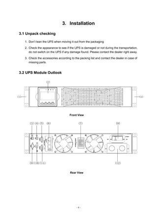
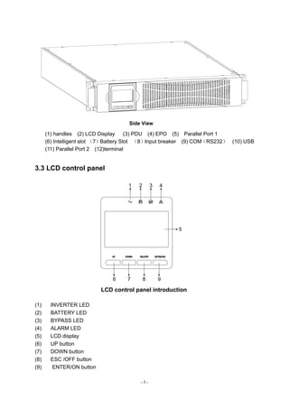
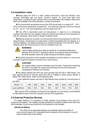
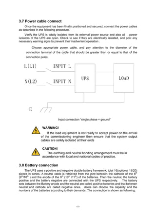
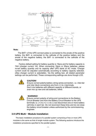
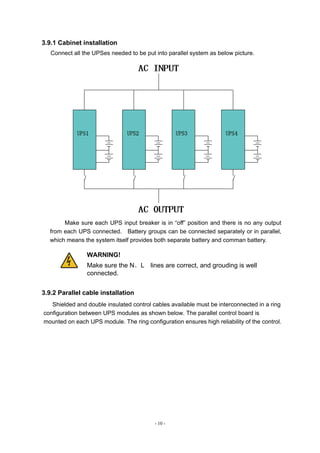
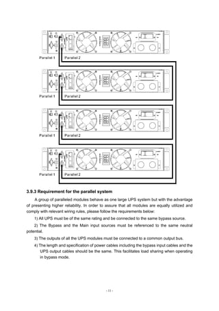
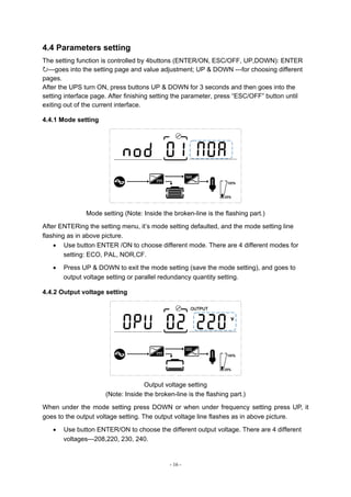
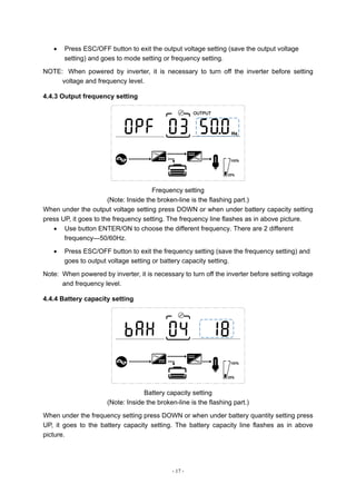
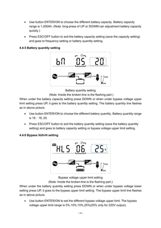
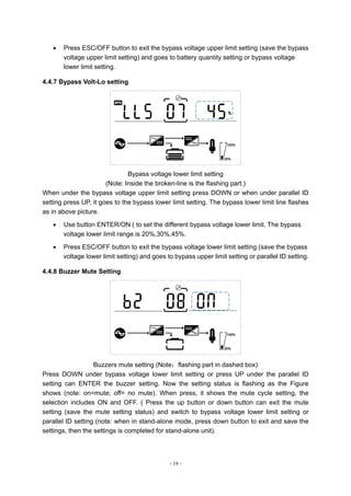
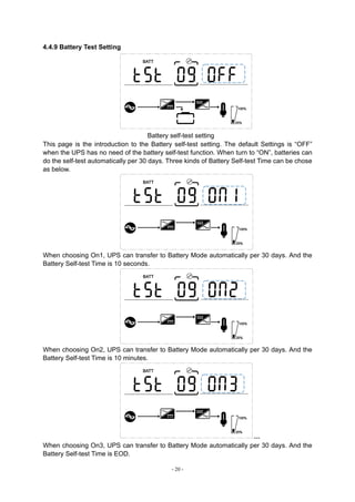
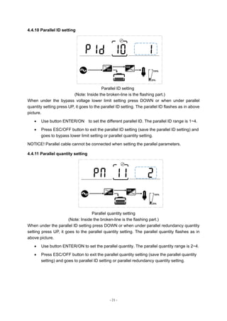
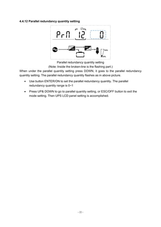
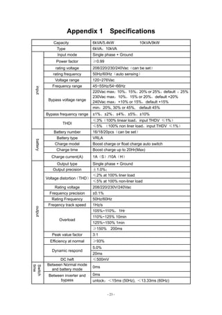
Manual Usuario
UPS ESOL RTH-C
6-10 kVA
ventas@enersafe.cl | www.enersafe.cl | +5641 3133345
All rights reserved.
The information in this document is subject to change without notice.
Publish statement
Thank you for purchasing this series UPS.
This series UPS is an intelligent, single phase in single phase out, high frequency
online UPS designed by our R&D team who is with years of designing experiences on
UPS. With excellent electrical performance, perfect intelligent monitoring and network
functions, smart appearance, complying with EMC and safety standards, This UPS
has become standard product which meets the world’s advanced level.
Read this manual carefully before installation
This manual offers technical support for equipment operator
- 1 -
Contents
1.Safety......................................................................................................................................................... - 2 -
1.1 Safety notes......................................................................................................................................... - 2 -
1.2 Symbols used in this guide............................................................................................................. - 2 -
2.Main Features.......................................................................................................................................... - 3 -
2.1 Summarization.................................................................................................................................... - 3 -
2.2 Functions and Features ................................................................................................................... - 3 -
3.Installation................................................................................................................................................ - 4 -
3.1 Unpack checking................................................................................................................................ - 4 -
3.2 UPS Module Outlook......................................................................................................................... - 4 -
3.3 LCD control panel.............................................................................................................................. - 5 -
3.4 Installation notes................................................................................................................................ - 6 -
3.5 External Protective Devices ............................................................................................................. - 6 -
3.6 Power Cables ....................................................................................................................................... - 7 -
3.7 Power cable connect......................................................................................................................... - 8 -
3.8 Battery connection ............................................................................................................................ - 8 -
3.9 UPS Multi-Module Installation ...................................................................................................... - 9 -
3.9.1 Cabinet installation.................................................................................................................. - 10 -
3.9.2 Parallel cable installation........................................................................................................ - 10 -
3.9.3 Requirement for the parallel system.....................................................................................- 11 -
4.Operation................................................................................................................................................ - 12 -
4.1 Operation Modes.............................................................................................................................. - 12 -
4.2 Turn on/off UPS ................................................................................................................................ - 12 -
4.2.1 Connecting with Utility............................................................................................................ - 12 -
4.2.2 Black(Cold) start procedure................................................................................................... - 13 -
4.2.3 Inverter Off ................................................................................................................................. - 13 -
4.2.4 Disconnecting with Utility ..................................................................................................... - 14 -
4.3 LCD Display instruction ................................................................................................................. - 14 -
4.4 Parameters setting .......................................................................................................................... - 16 -
4.4.1 Mode setting .............................................................................................................................. - 16 -
4.4.2 Output voltage setting............................................................................................................. - 16 -
4.4.3 Output frequency setting ....................................................................................................... - 17 -
4.4.4 Battery capacity setting.......................................................................................................... - 17 -
4.4.5 Battery quantity setting .......................................................................................................... - 18 -
4.4.6 Bypass Volt-Hi setting............................................................................................................. - 18 -
4.4.7 Bypass Volt-Lo setting............................................................................................................ - 19 -
4.4.8 Buzzer Mute Setting................................................................................................................. - 19 -
4.4.9 Battery Test Setting ................................................................................................................. - 20 -
4.4.10 Parallel ID setting ................................................................................................................... - 21 -
4.4.11 Parallel quantity setting........................................................................................................ - 21 -
4.4.12 Parallel redundancy quantity setting................................................................................ - 22 -
Appendix 1 Specifications..................................................................................................................... - 23 -
Appendix 2 Communication port definition...................................................................................... - 25 -
Appendix 3 Option................................................................................................................................... - 25 -
Appendix 4 UPS message table........................................................................................................... - 26 -
- 2 -
1.Safety
Important safety instructions – Save these instructions
There exists dangerous voltage and high temperature inside the UPS. During the
installation, operation and maintenance, please abide the local safety instructions and
relative laws, otherwise it will result in personnel injury or equipment damage. Safety
instructions in this manual act as a supplementary for the local safety instructions. Our
company will not assume the liability that caused by disobeying local safety instructions.
1.1 Safety notes
1.Even no connection with utility power, 208/220/230/240VAC voltage may still exist at
UPS outlet!
2.For the sake of human being safety, please well earth the UPS before starting it .
3.Don’t open or damage battery, for the liquid spilled from the battery is strongly
poisonous and do harmful to body!
4.Please avoid short circuit between anode and cathode of battery, otherwise, it will
cause spark or fire!
5.Don’t disassemble the UPS cover, or there may be an electric shock!
6.Check if there exists high voltage before touching the battery
7.Working environment and storage way will affect the lifetime and reliability of the UPS.
Avoid the UPS from working under following environment for long time
◆ Area where the humidity and temperature is out of the specified
range(temperature 0 to 40℃, relative humidity 5%-95%)
◆ Direct sunlight or location nearby heat
◆ Vibration Area with possibility to get the UPS crashed.
◆ Area with erosive gas, flammable gas, excessive dust, etc
8.Keep ventilations in good conditions otherwise the components inside the UPS will
be over-heated which may affect the life of the UPS.
1.2 Symbols used in this guide
WARNING!
Risk of electric shock
CAUTION!
Read this information to avoid equipment damage
- 3 -
2.Main Features
2.1 Summarization
This series UPS is a kind of single phase in single phase out high frequency online
UPS, it provides two capacities: The 6kVA and 10kVA. The products are modularized and
adopt the N+X redundancy. It can flexibly increase the number of the UPS modules
according to the load capacity which is convenient for flexible allocation and gradually
investment.
The UPS can solve most of the power supply problems, such as blackout, over-voltage,
under-voltage, voltage sudden drop, oscillating of decreasing extent, high voltage pulse,
voltage fluctuation, surge, inrush current, harmonic distortion (THD), noise interference,
frequency fluctuation, etc..
This UPS can be applied to different applications from computer device, automatic
equipment, communication system to industry equipment.
2.2 Functions and Features
◆1Phase In/1Phase Out UPS
It is 1Phase In/1Phase Out high-density UPS system, of which input current is kept in
balance. No unbalance problem might occur. And also support for single phase input.
◆Digital Control
This series UPS is controlled by Digital Signal Processor(DSP); ehance, it increases
reliability, performance, self-proteciton, self-diagnostics and so on.
◆Battery Configurable from 16pcs to 20pcs
The battery voltage of this series UPS can be configured at 16pcs, 18pcs or 20pcs
according to your convenience.
◆Intelligent Charging Method
The series UPS adopts advanced three-stage charging method—
1st
stage: high current constant current charging
to guarantee to charge back to 90%;
2nd
-stage: Constant Voltage
In order to vitalize battery and make sure batteries are fully charged
3rd
stage: floating mode.
With this 3-stage charging method, it extends the life of the batteries and guarantees fast
charging.
◆LCD Display
With LCD plus LED displays, the user may easily get UPS status and its operational
parameters, such as input/output voltage, frequency & load%, battery % and ambient
temperature, etc..
◆Intelligent Monitoring Function
Via optional SNMP Card, you may remotely control and monitor the UPS.
- 4 -
3.Installation
3.1 Unpack checking
1. Don’t lean the UPS when moving it out from the packaging
2. Check the appearance to see if the UPS is damaged or not during the transportation,
do not switch on the UPS if any damage found. Please contact the dealer right away.
3. Check the accessories according to the packing list and contact the dealer in case of
missing parts.
3.2 UPS Module Outlook
Front View
Rear View
- 5 -
Side View
(1) handles (2) LCD Display (3) PDU (4) EPO (5) Parallel Port 1
(6) Intelligent slot (7)Battery Slot (8)Input breaker (9) COM(RS232) (10) USB
(11) Parallel Port 2 (12)terminal
3.3 LCD control panel
1 2 3 4
5
6 7 8
LCD control panel introduction
(1) INVERTER LED
(2) BATTERY LED
(3) BYPASS LED
(4) ALARM LED
(5) LCD display
(6) UP button
(7) DOWN button
(8) ESC /OFF button
(9) ENTER/ON button
- 6 -
3.4 Installation notes
◆Please place the UPS in a clean, stable environment, avoid the vibration, dust,
humidity, flammable gas and liquid, corrosive objects. To avoid from high room
temperature, a system of room extractor fans is recommended to be installed. Optional air
filters are available if the UPS operates in a dusty environment.
◆The environment temperature around the UPS should keep in a range of 0℃~40℃.
If the environment temperature exceeds 40℃, the rated load capacity should be reduced
by 12% per 5℃. The max temperature can't be higher than 50℃.
◆If the UPS is dismantled under low temperature, it might be in a condensing
condition.The UPS can't be installed unless the internal and external of the equipment is
fully dry. Otherwise, there will be in danger of electric shock.
◆Batteries should be mounted in an environment where the temperature is within the
required specs. Temperature is a major factor in determining battery life and capacity. In a
normal installation, the battery temperature is maintained between 15°C and 25°C. Keep
batteries away from heat sources or main air ventilation area, etc.
WARNING!
Typical battery performance data are quoted for an operating temperature
between 20°C and 25°C. Operating it above this range will reduce the battery
life while operation below this range will reduce the battery capacity.
◆Should the equipment not be installed immediately it must be stored in a room so as
to protect it against excessive humidity and or heat sources。
CAUTION!
An unused battery must be recharged every 3months. Temporarily connecting
the UPS to a suitable AC supply and activating it for the time required for
recharging the batteries are required.
◆The highest altitude that UPS may work normally with full load is 1500 meters. The
load capacity should be reduced when this UPS is installed in place whose altitude is
higher than 1500 meters, shown as the following table:
(Load coefficient equals max load in high altitude place divided by nominal power of
the UPS)
Altitude(m) 1500 2000 2500 3000 3500 4000 4500 5000
Load coefficient 100% 95% 90% 85% 80% 75% 70% 65%
◆To get the UPS completely monitored by the software, you just simply connect RS232
or USB cable to each end of the computer and the UPS respectively.
3.5 External Protective Devices
For safety reasons, it is necessary to install, external circuit breaker at the input A.C.
supply and the battery. This chapter provides guidelines for qualified installers that must have
the knowledge of local wiring practices for the equipment to be installed.
◆External Battery
The UPS and its associated batteries are protected against the effect of
over-current through a DC compatible thermo-magnetic circuit-breaker (or a set of
fuses) located close to the battery.
- 7 -
◆UPS Output
Any external distribution board used for load distribution shall be fitted with
protective devices that may avoid the risk of UPS overloaded.
◆Over-current
Protection device shall be installed at the distribution panel of the incoming main
supply. It may identify the power cables current capacity as well as the overload
capacity of the system .
CAUTION !
Select a thermo magnetic circuit-breaker with an IEC 60947-2 trip curve C
(normal) for 125% of the current as listed below.
3.6 Power Cables
◆The cable design shall comply with the voltages and currents provided in this section,
Kindly follow local wiring practices and take into consideration the environmental conditions
(temperature and physical support media) .
WARNING!
UPON STARTING, PLEASE ENSURE THAT YOU ARE AWARE OF
THE LOCATION AND OPERATION OF THE EXTERNAL ISOLATORS
WHICH ARE CONNECTED TO THE UPS INPUT/BYPASS SUPPLY OF THE
MAINS DISTRIBUTION PANEL.CHECK TO SEE IF THESE SUPPLIES ARE
ELECTRICALLY ISOLATED, AND POST ANY NECESSARY WARNING
SIGNS TO PREVENT ANY INADVERTENT OPERATION.
Cable Dimension
UPS
module
Cable Dimension
AC Input
(mm2
)
AC Output
(mm2
)
DC Input
(mm2
)
Grounding
(mm2
)
6KVA 6 6 6 6
10KVA 10 10 10 10
CAUTION!
Protective earth cable: Connect each cabinet to the main ground
system. For Grounding connection, follow the shortest route
possible.
WARNING!
FAILURE TO FOLLOW ADEQUATE EARTHING PROCEDURES MAY
RESULT IN ELECTROMAGNETIC INTERFERENCE OR IN HAZARDS
INVOLVING ELECTRIC SHOCK AND FIRE.
- 8 -
3.7 Power cable connect
Once the equipment has been finally positioned and secured, connect the power cables
as described in the following procedure.
Verify the UPS is totally isolated from its external power source and also all power
isolators of the UPS are open. Check to see if they are electrically isolated, and post any
necessary warning signs to prevent their inadvertent operation .
Choose appropriate power cable, and pay attention to the diameter of the
connection terminal of the cable that should be greater than or equal to that of the
connection poles;
Input connection “single phase + ground”
WARNING!
If the load equipment is not ready to accept power on the arrival
of the commissioning engineer then ensure that the system output
cables are safely isolated at their ends
CAUTION!
The earthing and neutral bonding arrangement must be in
accordance with local and national codes of practice.
3.8 Battery connection
The UPS uses a positive and negative double battery framework, total 16(optional 18/20)
pieces in series. A neutral cable is retrieved from the joint between the cathode of the 8th
(9th
/10th
) and the anode of the 9th
(10th
/11th
) of the batteries. Then the neutral, the battery
positive and the battery negative are connected with the UPS respectively. The battery
sets between the Battery anode and the neutral are called positive batteries and that between
neutral and cathode are called negative ones. Users can choose the capacity and the
numbers of the batteries according to their demands. The connection is shown as following:
- 9 -
Note:
The BAT+ of the UPS connect poles is connected to the anode of the positive
battery, the BAT- is connected to the cathode of the positive battery and the
anode of the negative battery, the BAT- is connected to the cathode of the
negative battery。
Factory default setting for battery quantity is 16pcs and for battery capacity is
7AH (charger current 1A). When connecting 18pcs or 20pcs batteries, please
re-set battery quantity and its capacity after UPS starts at AC mode. Charger
current could be adjusted automatically according to battery capacity selected.
(Also charger current is selectable). Via the setting tool, all related parameter
settings can be performed. These corresponding settings are done though LCD.
CAUTION!
Ensure correct polarity battery string series connection. i.e. inter-tier
and inter block connections are from (+) to (-)terminals.
Don’t mix batteries with different capacity or different brands, or
even mix up new and old batteries, either.
WARNING!
Ensure correct polarity of string end connections to the Battery
Circuit Breaker and from the Battery Circuit Breaker to the UPS
terminals i.e. (+) to (+) / (-) to (-) but disconnect one or more battery
cell links in each tier. Do not reconnect these links and do not close
the battery circuit breaker unless authorized by the commissioning
engineer.
3.9 UPS Multi-Module Installation
The basic installation procedure of a parallel system comprising of two or more UPS
modules is the same as that of single module system. The following sections introduce the
installation procedures specified to the parallel system.
- 10 -
3.9.1 Cabinet installation
Connect all the UPSes needed to be put into parallel system as below picture.
Make sure each UPS input breaker is in “off” position and there is no any output
from each UPS connected. Battery groups can be connected separately or in parallel,
which means the system itself provides both separate battery and comman battery.
WARNING!
Make sure the N、L lines are correct, and grouding is well
connected.
3.9.2 Parallel cable installation
Shielded and double insulated control cables available must be interconnected in a ring
configuration between UPS modules as shown below. The parallel control board is
mounted on each UPS module. The ring configuration ensures high reliability of the control.
- 11 -
3.9.3 Requirement for the parallel system
A group of paralleled modules behave as one large UPS system but with the advantage
of presenting higher reliability. In order to assure that all modules are equally utilized and
comply with relevant wiring rules, please follow the requirements below:
1) All UPS must be of the same rating and be connected to the same bypass source.
2) The Bypass and the Main input sources must be referenced to the same neutral
potential.
3) The outputs of all the UPS modules must be connected to a common output bus.
4) The length and specification of power cables including the bypass input cables and the
UPS output cables should be the same. This facilitates load sharing when operating
in bypass mode.
- 12 -
4.Operation
4.1 Operation Modes
The UPS is a double-conversion on-line UPS that may operate in the following
alternative modes:
◆Normal mode
The rectifier/charger derives power from the AC Mains and supplies DC power to the
inverter while floating and boosting charge the battery simultaneously. Then, the inverter
converts the DC power to AC and supplies to the load.
◆Battery mode (Stored Energy Mode)
If the AC mains input power fails, the inverter, which obtains power from the battery,
supplies the critical AC load. There is no power interruption to the critical load. The UPS will
automatically return to Normal Mode when AC recovers.
◆Bypass mode
If the inverter is out of order, or if overload occurs, the static transfer switch will be
activated to transfer the load from the inverter supply to bypass supply without interruption to
the critical load. In the event that the inverter output is not synchronized with the bypass AC
source, the static switch will perform a transfer of the load from the inverter to the bypass with
power interruption to the critical AC load. This is to avoid paralleling of unsynchronized AC
sources. This interruption is programmable but typically set to be less than an electrical cycle
e.g. less than 15ms (50Hz) or less than 13.33ms (60Hz).
◆ECO Mode
When the UPS is at AC Mode and the requirement to the load is not critical, the UPS can
be set at ECO mode in order to increase the efficiency of the power supplied. At ECO
mode, the UPS works at Line-interactive mode, so the UPS will transfer to bypass supply.
When the AC is out of set window, the UPS will transfer from bypass to Inverter and
supplies power from the battery, then the LCD shows all related information on the
screen.
◆Parallel redundancy mode (system expansion)
To achieve a higher capacity and / or increase reliability, the outputs of up to four UPS
modules can be programmed to operate in parallel and the built-in parallel controller in each
UPS ensures automatic load sharing.
4.2 Turn on/off UPS
4.2.1 Connecting with Utility
CAUTION!
MAKE SURE GROUNDING IS PROPERLY DONE!
◆ Set the Battery Breaker to the “ON” position according to the user’s manual.
◆ Switch on the UPS
CAUTION!
Check to see if the load is safely connected with the output of the UPS. If
the load is not ready to receive power from the UPS, make sure that it is safely
isolated from the UPS output terminals
- 13 -
The internal fan of the UPS starts spinning, the UPS is performing self-diagnostics
until buzzer beeps twice to show the UPS is normal. Then, the UPS goes to bypass
supply, Utility LED and Bypass LED turn Green, the inverter is starting up now. When
the inverter is checked “normal”, the UPS goes to working mode and the load is
supplied by the inverter now.
No matter the UPS is operated normally or not, the LCD display will indicate
current status. The top lines display the UPS operational status and the bottom lines
indicate alarm conditions when they occur.
4.2.2 Black(Cold) start procedure
1 2 3 4
5
6 7 8
CAUTION!
Follow these procedures when the input AC Utility Failure, but battery is
normal
◆ Turn on the battery switch.
The battery will feed the Auxiliary power board.
◆ Trigger the cold start buttons at the position 9 in above drawing.
When battery normal, rectifier starts operation, 30s later, inverter starts
and operates, INV and output light up.
CAUTION!
Wait for approximately 30 seconds before you press the black start
key
4.2.3 Inverter Off
When the Utility is normal, press “ESC /OFF” button for approx. 1 sec until beep
sounds, the inverter LED will extinguish, the bypass LED on, then the UPS turns to
bypass supply.
When the UPS is on battery mode or without AC, press “ESC /OFF” button for
approx. 1 sec until beep sounds, the output of the UPS is off, fan stop spinning.After
60 seconds, all the LED on the LCD display extinguish.
- 14 -
4.2.4 Disconnecting with Utility
CAUTION!
This procedure should be followed to completely shut down the UPS
and the LOAD. After all power switches, isolators and circuit
breakers are opened, there will be no output.
◆After the inverter is off, turn the Utility and battery breakers to “OFF”, then
the LCD display will extinguish completely and fan stops spinning in 60
seconds. If there are external battery packs connected, please also
turn the battery breaker to “OFF”.
WARNING!
Wait for about 5 minutes for the internal D.C. bus bar capacitors to
be completely discharged.
4.3 LCD Display instruction
NOTICE! The display provides more functions than those described in this manual. There are
10 interfaces available in the LCD display:
ITEM
Interface
Description
Content Displayed
01 Input Voltage & Frequency
02 Output Voltage & Frequency
03 Bat.﹢ Voltage & Current
04 Bat. - Voltage & Current
05 Temperature
PFC/Internal temperature and
ambient temperature
06 Load Load
07 Bus voltage Bus voltage ±
08 Software version DSP version of inverter software
09 Model Model
1. When the UPS is connecting with the Utility or Battery at cold start mode, it shows as
drawing below:
(1) Operational Status and mode
- 15 -
1) Operational Status and mode When the UPS at single mode, it shows “NOA” or
“ECO”or“CF”, but If the UPS at parallel mode, it shows “PAL” instead.
2) Press “DOWN” button, the UPS goes to next page as shown below.
(2)Input voltage (3)Output voltage
(4)Bat + voltage (Positive) (5)Bat – voltage (Negative)
(6)Load (7) PFC/ Ambient temperature up, only shows
the high temperature Internal temperature
(down)
( 8 ) Bus voltage (9)Software version
- 16 -
4.4 Parameters setting
The setting function is controlled by 4buttons (ENTER/ON, ESC/OFF, UP,DOWN): ENTER
---goes into the setting page and value adjustment; UP & DOWN ---for choosing different
pages.
After the UPS turn ON, press buttons UP & DOWN for 3 seconds and then goes into the
setting interface page. After finishing setting the parameter, press “ESC/OFF” button until
exiting out of the current interface.
4.4.1 Mode setting
Mode setting (Note: Inside the broken-line is the flashing part.)
After ENTERing the setting menu, it’s mode setting defaulted, and the mode setting line
flashing as in above picture.
 Use button ENTER /ON to choose different mode. There are 4 different modes for
setting: ECO, PAL, NOR,CF.
 Press UP & DOWN to exit the mode setting (save the mode setting), and goes to
output voltage setting or parallel redundancy quantity setting.
4.4.2 Output voltage setting
Output voltage setting
(Note: Inside the broken-line is the flashing part.)
When under the mode setting press DOWN or when under frequency setting press UP, it
goes to the output voltage setting. The output voltage line flashes as in above picture.
 Use button ENTER/ON to choose the different output voltage. There are 4 different
voltages---208,220, 230, 240.
- 17 -
 Press ESC/OFF button to exit the output voltage setting (save the output voltage
setting) and goes to mode setting or frequency setting.
NOTE: When powered by inverter, it is necessary to turn off the inverter before setting
voltage and frequency level.
4.4.3 Output frequency setting
Frequency setting
(Note: Inside the broken-line is the flashing part.)
When under the output voltage setting press DOWN or when under battery capacity setting
press UP, it goes to the frequency setting. The frequency line flashes as in above picture.
 Use button ENTER/ON to choose the different frequency. There are 2 different
frequency---50/60Hz.
 Press ESC/OFF button to exit the frequency setting (save the frequency setting) and
goes to output voltage setting or battery capacity setting.
Note: When powered by inverter, it is necessary to turn off the inverter before setting voltage
and frequency level.
4.4.4 Battery capacity setting
Battery capacity setting
(Note: Inside the broken-line is the flashing part.)
When under the frequency setting press DOWN or when under battery quantity setting press
UP, it goes to the battery capacity setting. The battery capacity line flashes as in above
picture.
- 18 -
 Use button ENTER/ON to choose the different battery capacity. Battery capacity
range is 1-200Ah. (Note: long-press of UP or DOWM can adjustment battery capacity
quickly.)
 Press ESC/OFF button to exit the battery capacity setting (save the capacity setting)
and goes to frequency setting or battery quantity setting.
4.4.5 Battery quantity setting
Battery quantity setting
(Note: Inside the broken-line is the flashing part.)
When under the battery capacity setting press DOWN or when under bypass voltage upper
limit setting press UP, it goes to the battery quantity setting. The battery quantity line flashes
as in above picture.
 Use button ENTER/ON to choose the different battery quantity. Battery quantity range
is 16、18, 20.
 Press ESC/OFF button to exit the battery quantity setting (save the battery quantity
setting) and goes to battery capacity setting or bypass voltage upper limit setting.
4.4.6 Bypass Volt-Hi setting
Bypass voltage upper limit setting
(Note: Inside the broken-line is the flashing part.)
When under the battery quantity setting press DOWN or when under bypass voltage lower
setting press UP, it goes to the bypass upper limit setting. The bypass upper limit line flashes
as in above picture.
 Use button ENTER/ON to set the different bypass voltage upper limit. The bypass
voltage upper limit range is 5%,10%,15%,25%(25% only for 220V output).
- 19 -
 Press ESC/OFF button to exit the bypass voltage upper limit setting (save the bypass
voltage upper limit setting) and goes to battery quantity setting or bypass voltage
lower limit setting.
4.4.7 Bypass Volt-Lo setting
Bypass voltage lower limit setting
(Note: Inside the broken-line is the flashing part.)
When under the bypass voltage upper limit setting press DOWN or when under parallel ID
setting press UP, it goes to the bypass lower limit setting. The bypass lower limit line flashes
as in above picture.
 Use button ENTER/ON ( to set the different bypass voltage lower limit. The bypass
voltage lower limit range is 20%,30%,45%.
 Press ESC/OFF button to exit the bypass voltage lower limit setting (save the bypass
voltage lower limit setting) and goes to bypass upper limit setting or parallel ID setting.
4.4.8 Buzzer Mute Setting
Buzzers mute setting (Note:flashing part in dashed box)
Press DOWN under bypass voltage lower limit setting or press UP under the parallel ID
setting can ENTER the buzzer setting. Now the setting status is flashing as the Figure
shows (note: on=mute; off= no mute). When press, it shows the mute cycle setting, the
selection includes ON and OFF. ( Press the up button or down button can exit the mute
setting (save the mute setting status) and switch to bypass voltage lower limit setting or
parallel ID setting (note: when in stand-alone mode, press down button to exit and save the
settings, then the settings is completed for stand-alone unit).
- 20 -
4.4.9 Battery Test Setting
Battery self-test setting
This page is the introduction to the Battery self-test setting. The default Settings is “OFF”
when the UPS has no need of the battery self-test function. When turn to “ON”, batteries can
do the self-test automatically per 30 days. Three kinds of Battery Self-test Time can be chose
as below.
When choosing On1, UPS can transfer to Battery Mode automatically per 30 days. And the
Battery Self-test Time is 10 seconds.
When choosing On2, UPS can transfer to Battery Mode automatically per 30 days. And the
Battery Self-test Time is 10 minutes.
---
When choosing On3, UPS can transfer to Battery Mode automatically per 30 days. And the
Battery Self-test Time is EOD.
- 21 -
4.4.10 Parallel ID setting
Parallel ID setting
(Note: Inside the broken-line is the flashing part.)
When under the bypass voltage lower limit setting press DOWN or when under parallel
quantity setting press UP, it goes to the parallel ID setting. The parallel ID flashes as in above
picture.
 Use button ENTER/ON to set the different parallel ID. The parallel ID range is 1~4.
 Press ESC/OFF button to exit the parallel ID setting (save the parallel ID setting) and
goes to bypass lower limit setting or parallel quantity setting.
NOTICE! Parallel cable cannot be connected when setting the parallel parameters.
4.4.11 Parallel quantity setting
Parallel quantity setting
(Note: Inside the broken-line is the flashing part.)
When under the parallel ID setting press DOWN or when under parallel redundancy quantity
setting press UP, it goes to the parallel quantity setting. The parallel quantity flashes as in
above picture.
 Use button ENTER/ON to set the parallel quantity. The parallel quantity range is 2~4.
 Press ESC/OFF button to exit the parallel quantity setting (save the parallel quantity
setting) and goes to parallel ID setting or parallel redundancy quantity setting.
- 22 -
4.4.12 Parallel redundancy quantity setting
Parallel redundancy quantity setting
(Note: Inside the broken-line is the flashing part.)
When under the parallel quantity setting press DOWN, it goes to the parallel redundancy
quantity setting. The parallel redundancy quantity flashes as in above picture.
 Use button ENTER/ON to set the parallel redundancy quantity. The parallel
redundancy quantity range is 0~1
 Press UP& DOWN to go to parallel quantity setting, or ESC/OFF button to exit the
mode setting. Then UPS LCD panel setting is accomplished.
- 23 -
Appendix 1 Specifications
Capacity 6kVA/5.4kW 10kVA/9kW
Type 6kVA;10kVA
input
Input mode Single phase + Ground
Power factor ≥0.99
rating voltage 208/220/230/240Vac(can be set)
rating frequency 50Hz/60Hz(auto sensing)
Voltage range 120~276Vac
Frequency range 45~55Hz/54~66Hz
Bypass voltage range
220Vac max:10%,15%,20% or 25%,default :25%
230Vac max:10%,15% or 20%,default +20%
240Vac max:+10% or 15%,default +15%
min:20%, 30% or 45%, default 45%
Bypass frequency range ±1%、±2%、±4%、±5%、±10%
THDI
≤3%(100% linear load,input THDV ≤1%)
≤5% (100% non liner load,input THDV ≤1%)
battery
Battery number 16/18/20pcs(can be set)
Battery type VRLA
Charge model Boost charge or float charge auto switch
Charge time Boost charge up to 20Hr(Max)
Charge current(A) 1A(S)/10A(H)
output
Output type Single phase + Ground
Output precision ±1.0%;
Voltage distortion
(THD)
≤2% at 100% liner load
≤5% at 100% non-liner load
Rating voltage 208/220/230V/240Vac
Frequency precision ±0.1%
Rating Frequency 50Hz/60Hz
Freqency track speed 1Hz/s
Overload
105%~110%,1Hr
110%~125% 10min
125%~150% 1min
≥150% 200ms
Peak value factor 3:1
Efficiency at normal ≥93%
Dynamic respond
5.0%
20ms
DC heft ≤500mV
Switch
time
Between Normal mode
and battery mode
0ms
Between inverter and
bypass
0ms
unlock:<15ms (50Hz), <13.33ms (60Hz)
- 24 -
Norse <55dB(1m)
Display LCD+LED
Safety Meeting IEC62040-1 GB4943。
Max input voltage 320Vac,1Hr
EMI
Conduction :IEC 62040-2
Radiation :IEC 62040-2
Harmonics :IEC 62040-2
EMS IEC 62040-2
MTBF 250,000Hr 1+1 400,000Hr
MTTR 30min
Isolation resistance > 2MΩ(500Vdc)
Isolation intension 2820Vdc, <3.5mA,1min
Surge Meeting IEC60664-1 1.2/50uS+8/20uS 6kV/3kA.
Protection IP20
Parallel circumfluence 1+1≤8%,N+1≤3%
Parallel equal current 1+1≤8%,N+1≤10%
- 25 -
Appendix 2 Communication port definition
USB communication port
1 2
4 3
Definition of Male port:
Pin 1 VCC , Pin 2 D-
pin 3 D+ , Pin 4 GND
Application: use UPSilon2000 Power Management software
Available functions of the USB
■ Monitor UPS power status
■ Monitor UPS alarm info
■ Monitor UPS running parameters
■ Timing off/on setting
Appendix 3 Option
1. Dry contact card
2. SNMP card
3. Parallel card
- 26 -
Appendix 4 UPS message table
This section lists the alarm messages that the UPS might display. This section is listed with
each alarm message to help you troubleshoot problems .
4.1 Alarm Information
Item UPS Alarm Warning Buzz LED
1 Rectifier Fault Beep continuously Fault LED lit
2
Inverter fault(Including
Inverter bridge is shorted)
Beep continuously Fault LED lit
3 Inverter Thyristor short Beep continuously Fault LED lit
4 Inverter Thyristor broken Beep continuously Fault LED lit
5 Bypass Thyristor short Beep continuously Fault LED lit
6 Bypass Thyristor broken Beep continuously Fault LED lit
7 Fuse broken Beep continuously Fault LED lit
8 Parallel relay fault Beep continuously Fault LED lit
9 Fan fault Beep continuously Fault LED lit
10 Reserve Beep continuously Fault LED lit
11 Auxiliary power fault Beep continuously Fault LED lit
12 Initialization fault Beep continuously Fault LED lit
13 P-Battery Charger fault Beep continuously Fault LED lit
14 N-Battery Charger fault Beep continuously Fault LED lit
15 DC Bus over voltage Beep continuously Fault LED lit
16 DC Bus below voltage Beep continuously Fault LED lit
17 DC bus unbalance Beep continuously Fault LED lit
18 Soft start failed Beep continuously Fault LED lit
19 Rectifier Over Temperature Twice per second Fault LED lit
20 Inverter Over temperature Twice per second Fault LED lit
21 Reserve Twice per second Fault LED lit
22 Battery reverse Twice per second Fault LED lit
23 Cable connection error Twice per second Fault LED lit
24 CAN comm. Fault Twice per second Fault LED lit
25 Parallel load sharing fault Twice per second Fault LED lit
26 Battery over voltage Once per second Fault LED blinking
27 Mains Site Wiring Fault Once per second Fault LED blinking
28 Bypass Site Wiring Fault Once per second Fault LED blinking
29 Output Short-circuit Once per second Fault LED blinking
30 Rectifier over current Once per second Fault LED blinking
31 Bypass over current Once per second BPS LED blinking
32 Overload Once per second INV or BPS blinking
33 No battery Once per second BATTERY blinking
- 27 -
Item UPS Alarm Warning Buzz LED
34 Battery under voltage Once per second BATTERY blinking
35 Battery low pre-warning Once per second BATTERY blinking
36
Internal Communication
Error
Once per second Bypass LED lit
37 DC component over limit. Once per 2 seconds INV blinking
38 Parallel Overload Once per 2 seconds INV blinking
39 Mains volt. Abnormal Once per 2 seconds BATTERY LED lit
40 Mains freq. abnormal Once per 2 seconds BATTERY LED lit
41 Bypass Not Available BPS blinking
42 Bypass unable to trace BPS blinking
43 Inverter on invalid
45 EPO Beep continuously Fault LED lit

manual-de-Usuario-UPS-ENERSAFE-ESOL-RTH-C-6-10KVA.pdf

  • 1.
    Manual Usuario UPS ESOLRTH-C 6-10 kVA ventas@enersafe.cl | www.enersafe.cl | +5641 3133345
  • 2.
    All rights reserved. Theinformation in this document is subject to change without notice. Publish statement Thank you for purchasing this series UPS. This series UPS is an intelligent, single phase in single phase out, high frequency online UPS designed by our R&D team who is with years of designing experiences on UPS. With excellent electrical performance, perfect intelligent monitoring and network functions, smart appearance, complying with EMC and safety standards, This UPS has become standard product which meets the world’s advanced level. Read this manual carefully before installation This manual offers technical support for equipment operator
  • 3.
    - 1 - Contents 1.Safety.........................................................................................................................................................- 2 - 1.1 Safety notes......................................................................................................................................... - 2 - 1.2 Symbols used in this guide............................................................................................................. - 2 - 2.Main Features.......................................................................................................................................... - 3 - 2.1 Summarization.................................................................................................................................... - 3 - 2.2 Functions and Features ................................................................................................................... - 3 - 3.Installation................................................................................................................................................ - 4 - 3.1 Unpack checking................................................................................................................................ - 4 - 3.2 UPS Module Outlook......................................................................................................................... - 4 - 3.3 LCD control panel.............................................................................................................................. - 5 - 3.4 Installation notes................................................................................................................................ - 6 - 3.5 External Protective Devices ............................................................................................................. - 6 - 3.6 Power Cables ....................................................................................................................................... - 7 - 3.7 Power cable connect......................................................................................................................... - 8 - 3.8 Battery connection ............................................................................................................................ - 8 - 3.9 UPS Multi-Module Installation ...................................................................................................... - 9 - 3.9.1 Cabinet installation.................................................................................................................. - 10 - 3.9.2 Parallel cable installation........................................................................................................ - 10 - 3.9.3 Requirement for the parallel system.....................................................................................- 11 - 4.Operation................................................................................................................................................ - 12 - 4.1 Operation Modes.............................................................................................................................. - 12 - 4.2 Turn on/off UPS ................................................................................................................................ - 12 - 4.2.1 Connecting with Utility............................................................................................................ - 12 - 4.2.2 Black(Cold) start procedure................................................................................................... - 13 - 4.2.3 Inverter Off ................................................................................................................................. - 13 - 4.2.4 Disconnecting with Utility ..................................................................................................... - 14 - 4.3 LCD Display instruction ................................................................................................................. - 14 - 4.4 Parameters setting .......................................................................................................................... - 16 - 4.4.1 Mode setting .............................................................................................................................. - 16 - 4.4.2 Output voltage setting............................................................................................................. - 16 - 4.4.3 Output frequency setting ....................................................................................................... - 17 - 4.4.4 Battery capacity setting.......................................................................................................... - 17 - 4.4.5 Battery quantity setting .......................................................................................................... - 18 - 4.4.6 Bypass Volt-Hi setting............................................................................................................. - 18 - 4.4.7 Bypass Volt-Lo setting............................................................................................................ - 19 - 4.4.8 Buzzer Mute Setting................................................................................................................. - 19 - 4.4.9 Battery Test Setting ................................................................................................................. - 20 - 4.4.10 Parallel ID setting ................................................................................................................... - 21 - 4.4.11 Parallel quantity setting........................................................................................................ - 21 - 4.4.12 Parallel redundancy quantity setting................................................................................ - 22 - Appendix 1 Specifications..................................................................................................................... - 23 - Appendix 2 Communication port definition...................................................................................... - 25 - Appendix 3 Option................................................................................................................................... - 25 - Appendix 4 UPS message table........................................................................................................... - 26 -
  • 4.
    - 2 - 1.Safety Importantsafety instructions – Save these instructions There exists dangerous voltage and high temperature inside the UPS. During the installation, operation and maintenance, please abide the local safety instructions and relative laws, otherwise it will result in personnel injury or equipment damage. Safety instructions in this manual act as a supplementary for the local safety instructions. Our company will not assume the liability that caused by disobeying local safety instructions. 1.1 Safety notes 1.Even no connection with utility power, 208/220/230/240VAC voltage may still exist at UPS outlet! 2.For the sake of human being safety, please well earth the UPS before starting it . 3.Don’t open or damage battery, for the liquid spilled from the battery is strongly poisonous and do harmful to body! 4.Please avoid short circuit between anode and cathode of battery, otherwise, it will cause spark or fire! 5.Don’t disassemble the UPS cover, or there may be an electric shock! 6.Check if there exists high voltage before touching the battery 7.Working environment and storage way will affect the lifetime and reliability of the UPS. Avoid the UPS from working under following environment for long time ◆ Area where the humidity and temperature is out of the specified range(temperature 0 to 40℃, relative humidity 5%-95%) ◆ Direct sunlight or location nearby heat ◆ Vibration Area with possibility to get the UPS crashed. ◆ Area with erosive gas, flammable gas, excessive dust, etc 8.Keep ventilations in good conditions otherwise the components inside the UPS will be over-heated which may affect the life of the UPS. 1.2 Symbols used in this guide WARNING! Risk of electric shock CAUTION! Read this information to avoid equipment damage
  • 5.
    - 3 - 2.MainFeatures 2.1 Summarization This series UPS is a kind of single phase in single phase out high frequency online UPS, it provides two capacities: The 6kVA and 10kVA. The products are modularized and adopt the N+X redundancy. It can flexibly increase the number of the UPS modules according to the load capacity which is convenient for flexible allocation and gradually investment. The UPS can solve most of the power supply problems, such as blackout, over-voltage, under-voltage, voltage sudden drop, oscillating of decreasing extent, high voltage pulse, voltage fluctuation, surge, inrush current, harmonic distortion (THD), noise interference, frequency fluctuation, etc.. This UPS can be applied to different applications from computer device, automatic equipment, communication system to industry equipment. 2.2 Functions and Features ◆1Phase In/1Phase Out UPS It is 1Phase In/1Phase Out high-density UPS system, of which input current is kept in balance. No unbalance problem might occur. And also support for single phase input. ◆Digital Control This series UPS is controlled by Digital Signal Processor(DSP); ehance, it increases reliability, performance, self-proteciton, self-diagnostics and so on. ◆Battery Configurable from 16pcs to 20pcs The battery voltage of this series UPS can be configured at 16pcs, 18pcs or 20pcs according to your convenience. ◆Intelligent Charging Method The series UPS adopts advanced three-stage charging method— 1st stage: high current constant current charging to guarantee to charge back to 90%; 2nd -stage: Constant Voltage In order to vitalize battery and make sure batteries are fully charged 3rd stage: floating mode. With this 3-stage charging method, it extends the life of the batteries and guarantees fast charging. ◆LCD Display With LCD plus LED displays, the user may easily get UPS status and its operational parameters, such as input/output voltage, frequency & load%, battery % and ambient temperature, etc.. ◆Intelligent Monitoring Function Via optional SNMP Card, you may remotely control and monitor the UPS.
  • 6.
    - 4 - 3.Installation 3.1Unpack checking 1. Don’t lean the UPS when moving it out from the packaging 2. Check the appearance to see if the UPS is damaged or not during the transportation, do not switch on the UPS if any damage found. Please contact the dealer right away. 3. Check the accessories according to the packing list and contact the dealer in case of missing parts. 3.2 UPS Module Outlook Front View Rear View
  • 7.
    - 5 - SideView (1) handles (2) LCD Display (3) PDU (4) EPO (5) Parallel Port 1 (6) Intelligent slot (7)Battery Slot (8)Input breaker (9) COM(RS232) (10) USB (11) Parallel Port 2 (12)terminal 3.3 LCD control panel 1 2 3 4 5 6 7 8 LCD control panel introduction (1) INVERTER LED (2) BATTERY LED (3) BYPASS LED (4) ALARM LED (5) LCD display (6) UP button (7) DOWN button (8) ESC /OFF button (9) ENTER/ON button
  • 8.
    - 6 - 3.4Installation notes ◆Please place the UPS in a clean, stable environment, avoid the vibration, dust, humidity, flammable gas and liquid, corrosive objects. To avoid from high room temperature, a system of room extractor fans is recommended to be installed. Optional air filters are available if the UPS operates in a dusty environment. ◆The environment temperature around the UPS should keep in a range of 0℃~40℃. If the environment temperature exceeds 40℃, the rated load capacity should be reduced by 12% per 5℃. The max temperature can't be higher than 50℃. ◆If the UPS is dismantled under low temperature, it might be in a condensing condition.The UPS can't be installed unless the internal and external of the equipment is fully dry. Otherwise, there will be in danger of electric shock. ◆Batteries should be mounted in an environment where the temperature is within the required specs. Temperature is a major factor in determining battery life and capacity. In a normal installation, the battery temperature is maintained between 15°C and 25°C. Keep batteries away from heat sources or main air ventilation area, etc. WARNING! Typical battery performance data are quoted for an operating temperature between 20°C and 25°C. Operating it above this range will reduce the battery life while operation below this range will reduce the battery capacity. ◆Should the equipment not be installed immediately it must be stored in a room so as to protect it against excessive humidity and or heat sources。 CAUTION! An unused battery must be recharged every 3months. Temporarily connecting the UPS to a suitable AC supply and activating it for the time required for recharging the batteries are required. ◆The highest altitude that UPS may work normally with full load is 1500 meters. The load capacity should be reduced when this UPS is installed in place whose altitude is higher than 1500 meters, shown as the following table: (Load coefficient equals max load in high altitude place divided by nominal power of the UPS) Altitude(m) 1500 2000 2500 3000 3500 4000 4500 5000 Load coefficient 100% 95% 90% 85% 80% 75% 70% 65% ◆To get the UPS completely monitored by the software, you just simply connect RS232 or USB cable to each end of the computer and the UPS respectively. 3.5 External Protective Devices For safety reasons, it is necessary to install, external circuit breaker at the input A.C. supply and the battery. This chapter provides guidelines for qualified installers that must have the knowledge of local wiring practices for the equipment to be installed. ◆External Battery The UPS and its associated batteries are protected against the effect of over-current through a DC compatible thermo-magnetic circuit-breaker (or a set of fuses) located close to the battery.
  • 9.
    - 7 - ◆UPSOutput Any external distribution board used for load distribution shall be fitted with protective devices that may avoid the risk of UPS overloaded. ◆Over-current Protection device shall be installed at the distribution panel of the incoming main supply. It may identify the power cables current capacity as well as the overload capacity of the system . CAUTION ! Select a thermo magnetic circuit-breaker with an IEC 60947-2 trip curve C (normal) for 125% of the current as listed below. 3.6 Power Cables ◆The cable design shall comply with the voltages and currents provided in this section, Kindly follow local wiring practices and take into consideration the environmental conditions (temperature and physical support media) . WARNING! UPON STARTING, PLEASE ENSURE THAT YOU ARE AWARE OF THE LOCATION AND OPERATION OF THE EXTERNAL ISOLATORS WHICH ARE CONNECTED TO THE UPS INPUT/BYPASS SUPPLY OF THE MAINS DISTRIBUTION PANEL.CHECK TO SEE IF THESE SUPPLIES ARE ELECTRICALLY ISOLATED, AND POST ANY NECESSARY WARNING SIGNS TO PREVENT ANY INADVERTENT OPERATION. Cable Dimension UPS module Cable Dimension AC Input (mm2 ) AC Output (mm2 ) DC Input (mm2 ) Grounding (mm2 ) 6KVA 6 6 6 6 10KVA 10 10 10 10 CAUTION! Protective earth cable: Connect each cabinet to the main ground system. For Grounding connection, follow the shortest route possible. WARNING! FAILURE TO FOLLOW ADEQUATE EARTHING PROCEDURES MAY RESULT IN ELECTROMAGNETIC INTERFERENCE OR IN HAZARDS INVOLVING ELECTRIC SHOCK AND FIRE.
  • 10.
    - 8 - 3.7Power cable connect Once the equipment has been finally positioned and secured, connect the power cables as described in the following procedure. Verify the UPS is totally isolated from its external power source and also all power isolators of the UPS are open. Check to see if they are electrically isolated, and post any necessary warning signs to prevent their inadvertent operation . Choose appropriate power cable, and pay attention to the diameter of the connection terminal of the cable that should be greater than or equal to that of the connection poles; Input connection “single phase + ground” WARNING! If the load equipment is not ready to accept power on the arrival of the commissioning engineer then ensure that the system output cables are safely isolated at their ends CAUTION! The earthing and neutral bonding arrangement must be in accordance with local and national codes of practice. 3.8 Battery connection The UPS uses a positive and negative double battery framework, total 16(optional 18/20) pieces in series. A neutral cable is retrieved from the joint between the cathode of the 8th (9th /10th ) and the anode of the 9th (10th /11th ) of the batteries. Then the neutral, the battery positive and the battery negative are connected with the UPS respectively. The battery sets between the Battery anode and the neutral are called positive batteries and that between neutral and cathode are called negative ones. Users can choose the capacity and the numbers of the batteries according to their demands. The connection is shown as following:
  • 11.
    - 9 - Note: TheBAT+ of the UPS connect poles is connected to the anode of the positive battery, the BAT- is connected to the cathode of the positive battery and the anode of the negative battery, the BAT- is connected to the cathode of the negative battery。 Factory default setting for battery quantity is 16pcs and for battery capacity is 7AH (charger current 1A). When connecting 18pcs or 20pcs batteries, please re-set battery quantity and its capacity after UPS starts at AC mode. Charger current could be adjusted automatically according to battery capacity selected. (Also charger current is selectable). Via the setting tool, all related parameter settings can be performed. These corresponding settings are done though LCD. CAUTION! Ensure correct polarity battery string series connection. i.e. inter-tier and inter block connections are from (+) to (-)terminals. Don’t mix batteries with different capacity or different brands, or even mix up new and old batteries, either. WARNING! Ensure correct polarity of string end connections to the Battery Circuit Breaker and from the Battery Circuit Breaker to the UPS terminals i.e. (+) to (+) / (-) to (-) but disconnect one or more battery cell links in each tier. Do not reconnect these links and do not close the battery circuit breaker unless authorized by the commissioning engineer. 3.9 UPS Multi-Module Installation The basic installation procedure of a parallel system comprising of two or more UPS modules is the same as that of single module system. The following sections introduce the installation procedures specified to the parallel system.
  • 12.
    - 10 - 3.9.1Cabinet installation Connect all the UPSes needed to be put into parallel system as below picture. Make sure each UPS input breaker is in “off” position and there is no any output from each UPS connected. Battery groups can be connected separately or in parallel, which means the system itself provides both separate battery and comman battery. WARNING! Make sure the N、L lines are correct, and grouding is well connected. 3.9.2 Parallel cable installation Shielded and double insulated control cables available must be interconnected in a ring configuration between UPS modules as shown below. The parallel control board is mounted on each UPS module. The ring configuration ensures high reliability of the control.
  • 13.
    - 11 - 3.9.3Requirement for the parallel system A group of paralleled modules behave as one large UPS system but with the advantage of presenting higher reliability. In order to assure that all modules are equally utilized and comply with relevant wiring rules, please follow the requirements below: 1) All UPS must be of the same rating and be connected to the same bypass source. 2) The Bypass and the Main input sources must be referenced to the same neutral potential. 3) The outputs of all the UPS modules must be connected to a common output bus. 4) The length and specification of power cables including the bypass input cables and the UPS output cables should be the same. This facilitates load sharing when operating in bypass mode.
  • 14.
    - 12 - 4.Operation 4.1Operation Modes The UPS is a double-conversion on-line UPS that may operate in the following alternative modes: ◆Normal mode The rectifier/charger derives power from the AC Mains and supplies DC power to the inverter while floating and boosting charge the battery simultaneously. Then, the inverter converts the DC power to AC and supplies to the load. ◆Battery mode (Stored Energy Mode) If the AC mains input power fails, the inverter, which obtains power from the battery, supplies the critical AC load. There is no power interruption to the critical load. The UPS will automatically return to Normal Mode when AC recovers. ◆Bypass mode If the inverter is out of order, or if overload occurs, the static transfer switch will be activated to transfer the load from the inverter supply to bypass supply without interruption to the critical load. In the event that the inverter output is not synchronized with the bypass AC source, the static switch will perform a transfer of the load from the inverter to the bypass with power interruption to the critical AC load. This is to avoid paralleling of unsynchronized AC sources. This interruption is programmable but typically set to be less than an electrical cycle e.g. less than 15ms (50Hz) or less than 13.33ms (60Hz). ◆ECO Mode When the UPS is at AC Mode and the requirement to the load is not critical, the UPS can be set at ECO mode in order to increase the efficiency of the power supplied. At ECO mode, the UPS works at Line-interactive mode, so the UPS will transfer to bypass supply. When the AC is out of set window, the UPS will transfer from bypass to Inverter and supplies power from the battery, then the LCD shows all related information on the screen. ◆Parallel redundancy mode (system expansion) To achieve a higher capacity and / or increase reliability, the outputs of up to four UPS modules can be programmed to operate in parallel and the built-in parallel controller in each UPS ensures automatic load sharing. 4.2 Turn on/off UPS 4.2.1 Connecting with Utility CAUTION! MAKE SURE GROUNDING IS PROPERLY DONE! ◆ Set the Battery Breaker to the “ON” position according to the user’s manual. ◆ Switch on the UPS CAUTION! Check to see if the load is safely connected with the output of the UPS. If the load is not ready to receive power from the UPS, make sure that it is safely isolated from the UPS output terminals
  • 15.
    - 13 - Theinternal fan of the UPS starts spinning, the UPS is performing self-diagnostics until buzzer beeps twice to show the UPS is normal. Then, the UPS goes to bypass supply, Utility LED and Bypass LED turn Green, the inverter is starting up now. When the inverter is checked “normal”, the UPS goes to working mode and the load is supplied by the inverter now. No matter the UPS is operated normally or not, the LCD display will indicate current status. The top lines display the UPS operational status and the bottom lines indicate alarm conditions when they occur. 4.2.2 Black(Cold) start procedure 1 2 3 4 5 6 7 8 CAUTION! Follow these procedures when the input AC Utility Failure, but battery is normal ◆ Turn on the battery switch. The battery will feed the Auxiliary power board. ◆ Trigger the cold start buttons at the position 9 in above drawing. When battery normal, rectifier starts operation, 30s later, inverter starts and operates, INV and output light up. CAUTION! Wait for approximately 30 seconds before you press the black start key 4.2.3 Inverter Off When the Utility is normal, press “ESC /OFF” button for approx. 1 sec until beep sounds, the inverter LED will extinguish, the bypass LED on, then the UPS turns to bypass supply. When the UPS is on battery mode or without AC, press “ESC /OFF” button for approx. 1 sec until beep sounds, the output of the UPS is off, fan stop spinning.After 60 seconds, all the LED on the LCD display extinguish.
  • 16.
    - 14 - 4.2.4Disconnecting with Utility CAUTION! This procedure should be followed to completely shut down the UPS and the LOAD. After all power switches, isolators and circuit breakers are opened, there will be no output. ◆After the inverter is off, turn the Utility and battery breakers to “OFF”, then the LCD display will extinguish completely and fan stops spinning in 60 seconds. If there are external battery packs connected, please also turn the battery breaker to “OFF”. WARNING! Wait for about 5 minutes for the internal D.C. bus bar capacitors to be completely discharged. 4.3 LCD Display instruction NOTICE! The display provides more functions than those described in this manual. There are 10 interfaces available in the LCD display: ITEM Interface Description Content Displayed 01 Input Voltage & Frequency 02 Output Voltage & Frequency 03 Bat.﹢ Voltage & Current 04 Bat. - Voltage & Current 05 Temperature PFC/Internal temperature and ambient temperature 06 Load Load 07 Bus voltage Bus voltage ± 08 Software version DSP version of inverter software 09 Model Model 1. When the UPS is connecting with the Utility or Battery at cold start mode, it shows as drawing below: (1) Operational Status and mode
  • 17.
    - 15 - 1)Operational Status and mode When the UPS at single mode, it shows “NOA” or “ECO”or“CF”, but If the UPS at parallel mode, it shows “PAL” instead. 2) Press “DOWN” button, the UPS goes to next page as shown below. (2)Input voltage (3)Output voltage (4)Bat + voltage (Positive) (5)Bat – voltage (Negative) (6)Load (7) PFC/ Ambient temperature up, only shows the high temperature Internal temperature (down) ( 8 ) Bus voltage (9)Software version
  • 18.
    - 16 - 4.4Parameters setting The setting function is controlled by 4buttons (ENTER/ON, ESC/OFF, UP,DOWN): ENTER ---goes into the setting page and value adjustment; UP & DOWN ---for choosing different pages. After the UPS turn ON, press buttons UP & DOWN for 3 seconds and then goes into the setting interface page. After finishing setting the parameter, press “ESC/OFF” button until exiting out of the current interface. 4.4.1 Mode setting Mode setting (Note: Inside the broken-line is the flashing part.) After ENTERing the setting menu, it’s mode setting defaulted, and the mode setting line flashing as in above picture.  Use button ENTER /ON to choose different mode. There are 4 different modes for setting: ECO, PAL, NOR,CF.  Press UP & DOWN to exit the mode setting (save the mode setting), and goes to output voltage setting or parallel redundancy quantity setting. 4.4.2 Output voltage setting Output voltage setting (Note: Inside the broken-line is the flashing part.) When under the mode setting press DOWN or when under frequency setting press UP, it goes to the output voltage setting. The output voltage line flashes as in above picture.  Use button ENTER/ON to choose the different output voltage. There are 4 different voltages---208,220, 230, 240.
  • 19.
    - 17 - Press ESC/OFF button to exit the output voltage setting (save the output voltage setting) and goes to mode setting or frequency setting. NOTE: When powered by inverter, it is necessary to turn off the inverter before setting voltage and frequency level. 4.4.3 Output frequency setting Frequency setting (Note: Inside the broken-line is the flashing part.) When under the output voltage setting press DOWN or when under battery capacity setting press UP, it goes to the frequency setting. The frequency line flashes as in above picture.  Use button ENTER/ON to choose the different frequency. There are 2 different frequency---50/60Hz.  Press ESC/OFF button to exit the frequency setting (save the frequency setting) and goes to output voltage setting or battery capacity setting. Note: When powered by inverter, it is necessary to turn off the inverter before setting voltage and frequency level. 4.4.4 Battery capacity setting Battery capacity setting (Note: Inside the broken-line is the flashing part.) When under the frequency setting press DOWN or when under battery quantity setting press UP, it goes to the battery capacity setting. The battery capacity line flashes as in above picture.
  • 20.
    - 18 - Use button ENTER/ON to choose the different battery capacity. Battery capacity range is 1-200Ah. (Note: long-press of UP or DOWM can adjustment battery capacity quickly.)  Press ESC/OFF button to exit the battery capacity setting (save the capacity setting) and goes to frequency setting or battery quantity setting. 4.4.5 Battery quantity setting Battery quantity setting (Note: Inside the broken-line is the flashing part.) When under the battery capacity setting press DOWN or when under bypass voltage upper limit setting press UP, it goes to the battery quantity setting. The battery quantity line flashes as in above picture.  Use button ENTER/ON to choose the different battery quantity. Battery quantity range is 16、18, 20.  Press ESC/OFF button to exit the battery quantity setting (save the battery quantity setting) and goes to battery capacity setting or bypass voltage upper limit setting. 4.4.6 Bypass Volt-Hi setting Bypass voltage upper limit setting (Note: Inside the broken-line is the flashing part.) When under the battery quantity setting press DOWN or when under bypass voltage lower setting press UP, it goes to the bypass upper limit setting. The bypass upper limit line flashes as in above picture.  Use button ENTER/ON to set the different bypass voltage upper limit. The bypass voltage upper limit range is 5%,10%,15%,25%(25% only for 220V output).
  • 21.
    - 19 - Press ESC/OFF button to exit the bypass voltage upper limit setting (save the bypass voltage upper limit setting) and goes to battery quantity setting or bypass voltage lower limit setting. 4.4.7 Bypass Volt-Lo setting Bypass voltage lower limit setting (Note: Inside the broken-line is the flashing part.) When under the bypass voltage upper limit setting press DOWN or when under parallel ID setting press UP, it goes to the bypass lower limit setting. The bypass lower limit line flashes as in above picture.  Use button ENTER/ON ( to set the different bypass voltage lower limit. The bypass voltage lower limit range is 20%,30%,45%.  Press ESC/OFF button to exit the bypass voltage lower limit setting (save the bypass voltage lower limit setting) and goes to bypass upper limit setting or parallel ID setting. 4.4.8 Buzzer Mute Setting Buzzers mute setting (Note:flashing part in dashed box) Press DOWN under bypass voltage lower limit setting or press UP under the parallel ID setting can ENTER the buzzer setting. Now the setting status is flashing as the Figure shows (note: on=mute; off= no mute). When press, it shows the mute cycle setting, the selection includes ON and OFF. ( Press the up button or down button can exit the mute setting (save the mute setting status) and switch to bypass voltage lower limit setting or parallel ID setting (note: when in stand-alone mode, press down button to exit and save the settings, then the settings is completed for stand-alone unit).
  • 22.
    - 20 - 4.4.9Battery Test Setting Battery self-test setting This page is the introduction to the Battery self-test setting. The default Settings is “OFF” when the UPS has no need of the battery self-test function. When turn to “ON”, batteries can do the self-test automatically per 30 days. Three kinds of Battery Self-test Time can be chose as below. When choosing On1, UPS can transfer to Battery Mode automatically per 30 days. And the Battery Self-test Time is 10 seconds. When choosing On2, UPS can transfer to Battery Mode automatically per 30 days. And the Battery Self-test Time is 10 minutes. --- When choosing On3, UPS can transfer to Battery Mode automatically per 30 days. And the Battery Self-test Time is EOD.
  • 23.
    - 21 - 4.4.10Parallel ID setting Parallel ID setting (Note: Inside the broken-line is the flashing part.) When under the bypass voltage lower limit setting press DOWN or when under parallel quantity setting press UP, it goes to the parallel ID setting. The parallel ID flashes as in above picture.  Use button ENTER/ON to set the different parallel ID. The parallel ID range is 1~4.  Press ESC/OFF button to exit the parallel ID setting (save the parallel ID setting) and goes to bypass lower limit setting or parallel quantity setting. NOTICE! Parallel cable cannot be connected when setting the parallel parameters. 4.4.11 Parallel quantity setting Parallel quantity setting (Note: Inside the broken-line is the flashing part.) When under the parallel ID setting press DOWN or when under parallel redundancy quantity setting press UP, it goes to the parallel quantity setting. The parallel quantity flashes as in above picture.  Use button ENTER/ON to set the parallel quantity. The parallel quantity range is 2~4.  Press ESC/OFF button to exit the parallel quantity setting (save the parallel quantity setting) and goes to parallel ID setting or parallel redundancy quantity setting.
  • 24.
    - 22 - 4.4.12Parallel redundancy quantity setting Parallel redundancy quantity setting (Note: Inside the broken-line is the flashing part.) When under the parallel quantity setting press DOWN, it goes to the parallel redundancy quantity setting. The parallel redundancy quantity flashes as in above picture.  Use button ENTER/ON to set the parallel redundancy quantity. The parallel redundancy quantity range is 0~1  Press UP& DOWN to go to parallel quantity setting, or ESC/OFF button to exit the mode setting. Then UPS LCD panel setting is accomplished.
  • 25.
    - 23 - Appendix1 Specifications Capacity 6kVA/5.4kW 10kVA/9kW Type 6kVA;10kVA input Input mode Single phase + Ground Power factor ≥0.99 rating voltage 208/220/230/240Vac(can be set) rating frequency 50Hz/60Hz(auto sensing) Voltage range 120~276Vac Frequency range 45~55Hz/54~66Hz Bypass voltage range 220Vac max:10%,15%,20% or 25%,default :25% 230Vac max:10%,15% or 20%,default +20% 240Vac max:+10% or 15%,default +15% min:20%, 30% or 45%, default 45% Bypass frequency range ±1%、±2%、±4%、±5%、±10% THDI ≤3%(100% linear load,input THDV ≤1%) ≤5% (100% non liner load,input THDV ≤1%) battery Battery number 16/18/20pcs(can be set) Battery type VRLA Charge model Boost charge or float charge auto switch Charge time Boost charge up to 20Hr(Max) Charge current(A) 1A(S)/10A(H) output Output type Single phase + Ground Output precision ±1.0%; Voltage distortion (THD) ≤2% at 100% liner load ≤5% at 100% non-liner load Rating voltage 208/220/230V/240Vac Frequency precision ±0.1% Rating Frequency 50Hz/60Hz Freqency track speed 1Hz/s Overload 105%~110%,1Hr 110%~125% 10min 125%~150% 1min ≥150% 200ms Peak value factor 3:1 Efficiency at normal ≥93% Dynamic respond 5.0% 20ms DC heft ≤500mV Switch time Between Normal mode and battery mode 0ms Between inverter and bypass 0ms unlock:<15ms (50Hz), <13.33ms (60Hz)
  • 26.
    - 24 - Norse<55dB(1m) Display LCD+LED Safety Meeting IEC62040-1 GB4943。 Max input voltage 320Vac,1Hr EMI Conduction :IEC 62040-2 Radiation :IEC 62040-2 Harmonics :IEC 62040-2 EMS IEC 62040-2 MTBF 250,000Hr 1+1 400,000Hr MTTR 30min Isolation resistance > 2MΩ(500Vdc) Isolation intension 2820Vdc, <3.5mA,1min Surge Meeting IEC60664-1 1.2/50uS+8/20uS 6kV/3kA. Protection IP20 Parallel circumfluence 1+1≤8%,N+1≤3% Parallel equal current 1+1≤8%,N+1≤10%
  • 27.
    - 25 - Appendix2 Communication port definition USB communication port 1 2 4 3 Definition of Male port: Pin 1 VCC , Pin 2 D- pin 3 D+ , Pin 4 GND Application: use UPSilon2000 Power Management software Available functions of the USB ■ Monitor UPS power status ■ Monitor UPS alarm info ■ Monitor UPS running parameters ■ Timing off/on setting Appendix 3 Option 1. Dry contact card 2. SNMP card 3. Parallel card
  • 28.
    - 26 - Appendix4 UPS message table This section lists the alarm messages that the UPS might display. This section is listed with each alarm message to help you troubleshoot problems . 4.1 Alarm Information Item UPS Alarm Warning Buzz LED 1 Rectifier Fault Beep continuously Fault LED lit 2 Inverter fault(Including Inverter bridge is shorted) Beep continuously Fault LED lit 3 Inverter Thyristor short Beep continuously Fault LED lit 4 Inverter Thyristor broken Beep continuously Fault LED lit 5 Bypass Thyristor short Beep continuously Fault LED lit 6 Bypass Thyristor broken Beep continuously Fault LED lit 7 Fuse broken Beep continuously Fault LED lit 8 Parallel relay fault Beep continuously Fault LED lit 9 Fan fault Beep continuously Fault LED lit 10 Reserve Beep continuously Fault LED lit 11 Auxiliary power fault Beep continuously Fault LED lit 12 Initialization fault Beep continuously Fault LED lit 13 P-Battery Charger fault Beep continuously Fault LED lit 14 N-Battery Charger fault Beep continuously Fault LED lit 15 DC Bus over voltage Beep continuously Fault LED lit 16 DC Bus below voltage Beep continuously Fault LED lit 17 DC bus unbalance Beep continuously Fault LED lit 18 Soft start failed Beep continuously Fault LED lit 19 Rectifier Over Temperature Twice per second Fault LED lit 20 Inverter Over temperature Twice per second Fault LED lit 21 Reserve Twice per second Fault LED lit 22 Battery reverse Twice per second Fault LED lit 23 Cable connection error Twice per second Fault LED lit 24 CAN comm. Fault Twice per second Fault LED lit 25 Parallel load sharing fault Twice per second Fault LED lit 26 Battery over voltage Once per second Fault LED blinking 27 Mains Site Wiring Fault Once per second Fault LED blinking 28 Bypass Site Wiring Fault Once per second Fault LED blinking 29 Output Short-circuit Once per second Fault LED blinking 30 Rectifier over current Once per second Fault LED blinking 31 Bypass over current Once per second BPS LED blinking 32 Overload Once per second INV or BPS blinking 33 No battery Once per second BATTERY blinking
  • 29.
    - 27 - ItemUPS Alarm Warning Buzz LED 34 Battery under voltage Once per second BATTERY blinking 35 Battery low pre-warning Once per second BATTERY blinking 36 Internal Communication Error Once per second Bypass LED lit 37 DC component over limit. Once per 2 seconds INV blinking 38 Parallel Overload Once per 2 seconds INV blinking 39 Mains volt. Abnormal Once per 2 seconds BATTERY LED lit 40 Mains freq. abnormal Once per 2 seconds BATTERY LED lit 41 Bypass Not Available BPS blinking 42 Bypass unable to trace BPS blinking 43 Inverter on invalid 45 EPO Beep continuously Fault LED lit