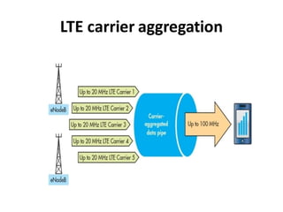
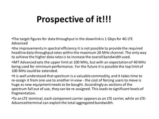
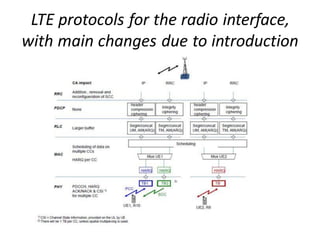
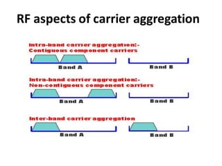
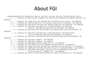
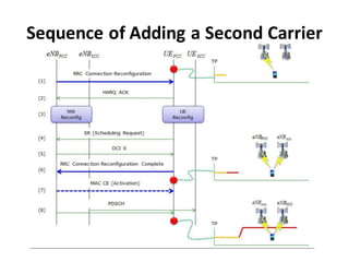
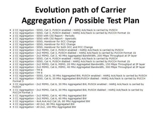
LTE carrier aggregation
Prospective of it!!!
•The target figures for datathroughput in the downlinkis 1 Gbps for 4G LTE
Advanced
•the improvementsin spectral efficiency it is not possible to provide the required
headlinedata throughputrates within the maximum 20 MHz channel. The only way
to achieve the higher data ratesis to increase the overallbandwidthused.
•IMT Advancedsets the upper limit at 100 MHz, but with an expectationof 40 MHz
being used for minimum performance. For the future it is possible the top limit of
100 MHz could be extended.
•It is well understood that spectrum is a valuablecommodity, and it takes time to
re-assign it from one use to another in view - the cost of forcing users to move is
huge as new equipmentneeds to be bought. Accordinglyas sections of the
spectrum fall out of use, they can be re-assigned. This leads to significant levelsof
fragmentation.
•To an LTE terminal, each component carrier appears as an LTE carrier, while an LTE-
Advancedterminal can exploit the total aggregated bandwidth.
LTE protocols for the radio interface,
with main changes due to introduction
of CA.
RF aspects of carrier aggregation
Detail of it
•Intra-band:
This form of carrier aggregationuses a single band. There are two main formatsfor this
type of carrier aggregation.
1-> Contiguous:
The Intra-bandcontiguous carrier aggregation is the easiest form of LTE carrier
aggregation to implement. Here the carriers are adjacentto each other. The
aggregated channel can be considered by the terminal as a single enlarged channel
from the RF viewpoint.In this instance,only one transceiver is required within the
terminal or UE, whereas more are required where the channels are not adjacent.
However as the RF bandwidthincreases it is necessary to ensure that the UE in
particular is able to operate over such a wide bandwidthwithout a reduction in
performance. Although the performance requirementsare the same for the base
station,the space, power consumption,and cost requirementsare considerablyless
stringent, allowinggreater flexibilityin the design. Additionallyfor the base station,
multi-carrier operation,even if non-aggregated, is alreadya requirement in many
instances, requiring little or no change to the RF elementsof the design. Software
upgrades wouldnaturallybe required to cater for the additional capability
Continuation……
2->Non-contiguous:
Non-contiguous intra-band carrier aggregation is somewhat more complicated
than the instance where adjacent carriers are used. No longer can the multi-
carrier signal be treated as a single signal and therefore two transceivers are
required. This adds significant complexity, particularly to the UE where space,
power and cost are prime considerations.
Inter-band non-contiguous
This form of carrier aggregation uses different bands. It will be of particularuse
because of the fragmentationof bands - some of which are only 10 MHz wide. For
the UE it requires the use of multipletransceiverswithin the single item, with the
usual impact on cost, performance and power. In additionto this there are also
additional complexitiesresulting from the requirementsto reduce inter-modulation
and cross modulationfrom the two transceivers
Note:
The current standards allowfor up to five 20 MHz carriers to be aggregated,
althoughin practice two or three is likely to be the practicallimit. These aggregated
carriers can be transmitted in parallelto or from the same terminal, thereby
enablinga much higher throughput to be obtained
LTE carrier aggregation bandwidth
classes
There is a total of six different carrier aggregation, CA bandwidthclasses which are
being defined.
LTE aggregated carriers
When carriers are aggregated, each carrier is referred to as a component carrier.
There are two categories:
•Primarycomponent carrier:
This is the main carrier in any group. There will be a primary downlinkcarrier and an
associated uplinkprimary component carrier.
•Secondary component carrier:
There may be one or more secondary component carriers.
Carrier aggregation cross carrier
scheduling
Carrier aggregation cross carrier
scheduling
•When LTE carrier aggregation is used, it is necessary to be able to schedule the data
across the carriers and to inform the terminal of the DCI ratesfor the different
component carriers. This informationmay be implicit, or it may be explicit
dependent upon whether cross carrier scheduling is used.
•Enablingof the cross carrier scheduling is achieved individuallyvia the RRC signaling
on a per component carrier basisor a per terminal basis.
•When no cross carrier scheduling is arranged, the downlinkscheduling assignments
achievedon a per carrier basis, i.e. they are validfor the componentcarrier on which
they were transmitted.
•For the uplink, an associationis created between one downlinkcomponentcarrier
and an uplinkcomponent carrier. In this way when uplinkgrants are sent the
terminal or UE will know to which uplink componentcarrier they apply.
•Where cross carrier scheduling is active, the PDSCH on the downlinkor the PUSCH
on the uplinkis transmittedon an associate component carrier other than the
PDCCH, the carrier indicatorin the PDCCH provides the information about the
component carrier used for the PDSCH or PUSCH.
How a Network know if a UE support
Carrier Aggregation ?
The most important thing you have to pay attentionin UE CapabilityInformationis
CA Band combinationas specified in RRC message as shown below.
Check the Next Slide for Message!!!!!!!
About FGI
Sequence of Adding a Second Carrier
Evolution path of Carrier
Aggregation / Possible Test Plan

LTE Carrier Aggregation about the aggregation

  • 1.
  • 2.
    Prospective of it!!! •Thetarget figures for datathroughput in the downlinkis 1 Gbps for 4G LTE Advanced •the improvementsin spectral efficiency it is not possible to provide the required headlinedata throughputrates within the maximum 20 MHz channel. The only way to achieve the higher data ratesis to increase the overallbandwidthused. •IMT Advancedsets the upper limit at 100 MHz, but with an expectationof 40 MHz being used for minimum performance. For the future it is possible the top limit of 100 MHz could be extended. •It is well understood that spectrum is a valuablecommodity, and it takes time to re-assign it from one use to another in view - the cost of forcing users to move is huge as new equipmentneeds to be bought. Accordinglyas sections of the spectrum fall out of use, they can be re-assigned. This leads to significant levelsof fragmentation. •To an LTE terminal, each component carrier appears as an LTE carrier, while an LTE- Advancedterminal can exploit the total aggregated bandwidth.
  • 3.
    LTE protocols forthe radio interface, with main changes due to introduction of CA.
  • 4.
    RF aspects ofcarrier aggregation
  • 5.
    Detail of it •Intra-band: Thisform of carrier aggregationuses a single band. There are two main formatsfor this type of carrier aggregation. 1-> Contiguous: The Intra-bandcontiguous carrier aggregation is the easiest form of LTE carrier aggregation to implement. Here the carriers are adjacentto each other. The aggregated channel can be considered by the terminal as a single enlarged channel from the RF viewpoint.In this instance,only one transceiver is required within the terminal or UE, whereas more are required where the channels are not adjacent. However as the RF bandwidthincreases it is necessary to ensure that the UE in particular is able to operate over such a wide bandwidthwithout a reduction in performance. Although the performance requirementsare the same for the base station,the space, power consumption,and cost requirementsare considerablyless stringent, allowinggreater flexibilityin the design. Additionallyfor the base station, multi-carrier operation,even if non-aggregated, is alreadya requirement in many instances, requiring little or no change to the RF elementsof the design. Software upgrades wouldnaturallybe required to cater for the additional capability
  • 6.
    Continuation…… 2->Non-contiguous: Non-contiguous intra-band carrieraggregation is somewhat more complicated than the instance where adjacent carriers are used. No longer can the multi- carrier signal be treated as a single signal and therefore two transceivers are required. This adds significant complexity, particularly to the UE where space, power and cost are prime considerations.
  • 7.
    Inter-band non-contiguous This formof carrier aggregation uses different bands. It will be of particularuse because of the fragmentationof bands - some of which are only 10 MHz wide. For the UE it requires the use of multipletransceiverswithin the single item, with the usual impact on cost, performance and power. In additionto this there are also additional complexitiesresulting from the requirementsto reduce inter-modulation and cross modulationfrom the two transceivers Note: The current standards allowfor up to five 20 MHz carriers to be aggregated, althoughin practice two or three is likely to be the practicallimit. These aggregated carriers can be transmitted in parallelto or from the same terminal, thereby enablinga much higher throughput to be obtained
  • 8.
    LTE carrier aggregationbandwidth classes There is a total of six different carrier aggregation, CA bandwidthclasses which are being defined.
  • 9.
    LTE aggregated carriers Whencarriers are aggregated, each carrier is referred to as a component carrier. There are two categories: •Primarycomponent carrier: This is the main carrier in any group. There will be a primary downlinkcarrier and an associated uplinkprimary component carrier. •Secondary component carrier: There may be one or more secondary component carriers.
  • 10.
    Carrier aggregation crosscarrier scheduling
  • 11.
    Carrier aggregation crosscarrier scheduling •When LTE carrier aggregation is used, it is necessary to be able to schedule the data across the carriers and to inform the terminal of the DCI ratesfor the different component carriers. This informationmay be implicit, or it may be explicit dependent upon whether cross carrier scheduling is used. •Enablingof the cross carrier scheduling is achieved individuallyvia the RRC signaling on a per component carrier basisor a per terminal basis. •When no cross carrier scheduling is arranged, the downlinkscheduling assignments achievedon a per carrier basis, i.e. they are validfor the componentcarrier on which they were transmitted. •For the uplink, an associationis created between one downlinkcomponentcarrier and an uplinkcomponent carrier. In this way when uplinkgrants are sent the terminal or UE will know to which uplink componentcarrier they apply. •Where cross carrier scheduling is active, the PDSCH on the downlinkor the PUSCH on the uplinkis transmittedon an associate component carrier other than the PDCCH, the carrier indicatorin the PDCCH provides the information about the component carrier used for the PDSCH or PUSCH.
  • 12.
    How a Networkknow if a UE support Carrier Aggregation ? The most important thing you have to pay attentionin UE CapabilityInformationis CA Band combinationas specified in RRC message as shown below. Check the Next Slide for Message!!!!!!!
  • 14.
  • 15.
    Sequence of Addinga Second Carrier
  • 16.
    Evolution path ofCarrier Aggregation / Possible Test Plan