The document provides information about P Series LED screens including:
- The P Series is designed for outdoor stadiums and has an IP65 weatherproof rating. It has pixel densities ranging from 3,906 to 10,000 pixels/m2.
- Technical parameters include dot spacing, pixel configuration, brightness, grayscale, refresh rate, power consumption, and operating temperature and humidity ranges.
- The document describes the cabinet components including modules, cabinet parts, and wire connections. It also provides installation instructions and required tools.
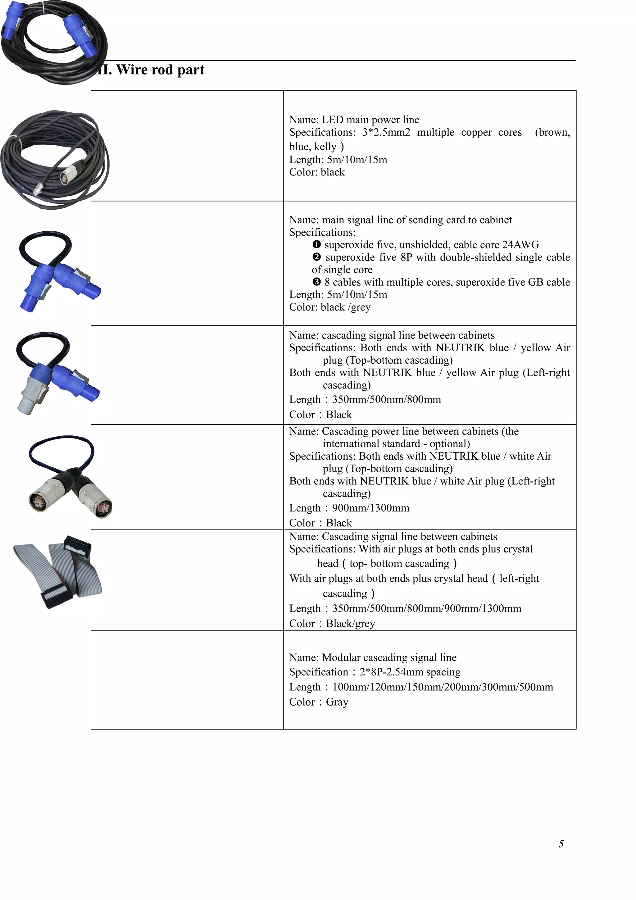
![II. Introduction P Series LED Screens Products
[I] Size of LED screen
1](https://image.slidesharecdn.com/ledperimeterscreen-180821075021/75/Led-perimeter-screen-1-2048.jpg)
![[II] Product features and parameters
P Series is designed for stadiums.
The unique structure design is convenient for installation and maintenance.
PO Series comes with outdoor weather proof IP65.
EMC & CE certified interior design.
P series technical parameters
Dot spacing 10mm 10mm 12mm 12mm 16mm 20mm
Pixel Configuration SMD3535 DIP346 SMD3535 DIP346 DIP346 DIP346
Pixel Density (/m2
) 10000 6944 3906 2500
Applicable Environment Outdoor
Module Size (mm) 240*160 160*160 192*192 256*128 320*160
Module Resolution 24*16 16*16 16*16 16*8 16*8
Cabinet Size (mm) 1920*960 1920*960 1920*960 1792*896 1920*960
Cabinet Resolution 192*96 192*96 160*80 112*56 96*48
Scanning Mode 1/2 1/4 Static 1/2 Static Static
Brightness (cd/m2
) ≥8000 ≥6000 ≥8000 ≥6000 ≥6000 ≥6000
Gray Scale (bit) ≥12
Refresh Rate (Hz) ≥800 ≥800 ≥1200 ≥800 ≥1200 ≥1200
Cabinet Weight (Kg) 50±1 58±1 52±1 58±1 58±1 58±1
Power Consumption (W/pc) ≤1000 ≤570 ≤1000 ≤570 ≤570 ≤570
Input voltage (V) 100-120V/110-220V/100-240V 50/60Hz
Viewing Angle SMD--H:140° V:140° DIP--H:120° V:90°
Temperature Range (℃) Storage:-40℃~+85℃;Operation:-30℃~+50℃
Operating Humidity 10-90% RH
Service Life 100,000H
MTBF 5000H
IP Rating Front SideIP65,Back SideIP54
2](https://image.slidesharecdn.com/ledperimeterscreen-180821075021/75/Led-perimeter-screen-2-2048.jpg)
![[III] Introduction to accessories’functions
[IV] Cabinet
(1) Module
Two-hole rectangle connect – Connect & fix each
cabinet.
Weight :
Color:Black
SMD LED
Signal interface
Module power supply
DIP LED
3](https://image.slidesharecdn.com/ledperimeterscreen-180821075021/75/Led-perimeter-screen-3-2048.jpg)

![IV. LED installation
[I] Installation tools and accessories
M10*25mm screw – fixing the
cabinet for vertical and hoisting
installation
S8 internal hexagonal wrench –
used for tightening M10mm
screw
Cross screwdriver
Digital multimeter – used for
measuring circuit
Key – used to open or lock
cabinet back door
6](https://image.slidesharecdn.com/ledperimeterscreen-180821075021/75/Led-perimeter-screen-6-2048.jpg)
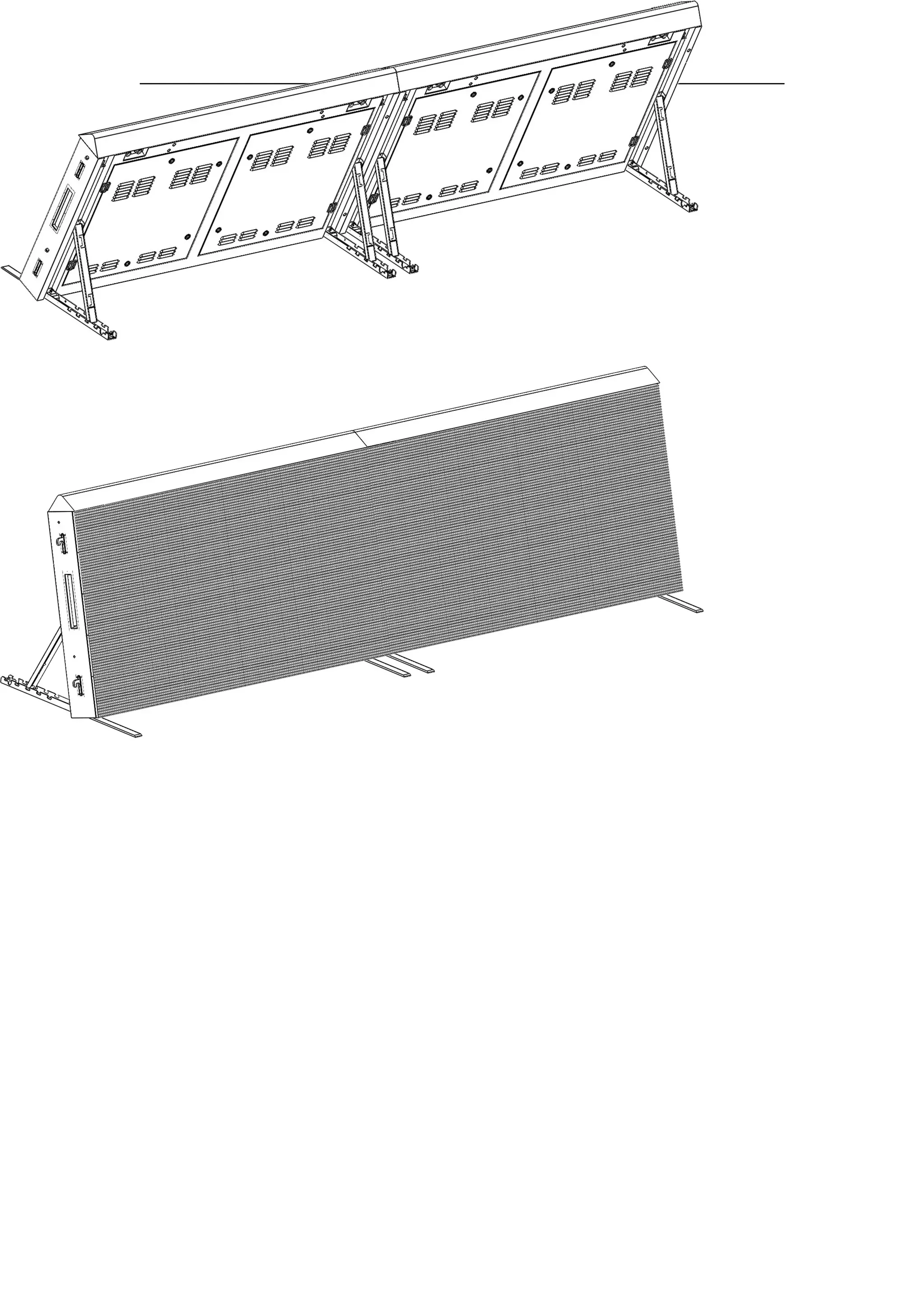
![[II] Installation method
(1) Viewing angle can be adjustbale
(2) Installation steps
Pull out (upward) latch locking of the
bottom support at the cabinet’s both
sides, and locate the bottom support
well.
Push out the front support plate from
the bottom support, and make it pass
through the cabinet bottom.
Pull out (downward) latch locking of
the diagonal support at the cabinet’s
both sides, and locate the diagonal
support well.](https://image.slidesharecdn.com/ledperimeterscreen-180821075021/75/Led-perimeter-screen-7-2048.jpg)