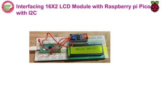
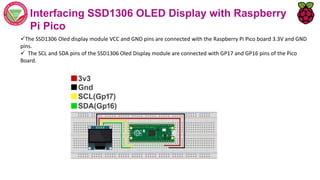
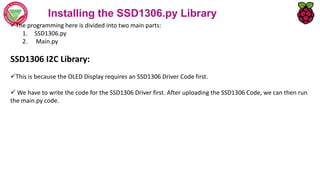
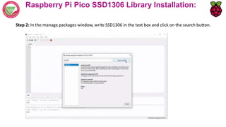
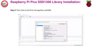
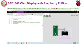
Course Outcomes
Course Outcomes
CO1
Understand general concepts of Internet of Things (IoT), the
working of Raspberry Pi and its features.
CO2
Recognize various components, sensors, actuators, devices and
their applications.
CO3 Analyze various python programs to interface with sensors, actuators,
LED’s, cloud and camera using Raspberry pi.
CO4 Measure physical parameters using sensors.
CO5
Demonstrate the ability to transmit data wirelessly between
different devices to build simple IoT systems using Raspberry Pi.
CO6
Create IoT devices and systems through a variety of interfaces,
including web apps and mobile apps.
Interfacing 16X2 LCD Module with Raspberry pi Pico with
and without I2C
Liquid Crystal Display (LCDs)
 The liquid crystal display are normally used in different embedded projects due to its low cost, easy access
and flexibility to get programmed.
There is a type of liquid display that has sixteen column and two rows so it is known as 16 x 2 LCD modules.
LCD also available in different arrangements like (8 x 1), (10 x 2), (16 x 1), but the 16 x 2 liquid crystal is
normally used in embedded projects.
 In this liquid crystal display, there are thirty-two characters and each of them consists of 5 x 8 pixels.
Pinout of 16x2 LCD Module
 These are the main pinouts of 16 x 2 LCD that are described here with the detailed
LCD functions – displaying text
 The LCD is connected to the Pico using 4 data wires (D4 – D7) and 2 control wires (E and R/S).
 The connections between the LCD and Pico are as follows:
Interfacing 16X2 LCD Module with Raspberry pi Pico
without I2C
Interfacing 16X2 LCD Module with Raspberry pi Pico with I2C
I2C
 Communication over I2C takes place on two wires: a clock (usually marked as SCL) and a data channel (usually
marked SDA)
The pinout for Raspberry Pi Pico
16X2 I2C LCD Display
This display incorporates an I2C interface that requires only 2 pins on a microcontroller to the interface.
 The I2C interface is a daughter board attached to the back of the LCD module.
The I2C address for these displays is either 0x3F or 0x27.
Circuit diagram
 The LCD module VCC and GND are powered from VBUS(pin40) and GND (pin38) pins of Raspberry
pi Pico board respectively.
 The data pins of LCD module SDA and SCL are connected to GP8(pin11) and GP9(pin12) of Pico
board
Interfacing 16X2 LCD Module with Raspberry pi Pico
with I2C
 LCD display I2C requires few pre coded libraries
lcd_api.py
pico_i2c_lcd.py
Interfacing 16X2 LCD Module with Raspberry pi Pico
with I2C
OLED
OLED (organic light-emitting diode) displays are low-power consumption output devices able to show
text and images by controlling every single pixel.
The most common size is 128×64 pixels (0.96 inches), but also the 128×32 pixels (0.91 inches) is
available from e-shops.
Their screens are usually mono-colour or bi-colour. The mono-colour ones are made of blue or white
pixels, while the bi-colour models usually have an upper part yellow and the lower one blue.
SSD1306 OLED Pinout
There are four pins in this display. Imprinted as VCC, GND, SCL, and SDA respectively.
The VCC and GND pins will power the OLED display and will be connected with the Raspberry Pi Pico
board’s power supply pins as they require a driving voltage of 3.3-5V.
The SCL and SDA pins are necessary for generating the clock signal and in the transmission of data
respectively. Both of these pins will be connected with the I2C pins of the Raspberry Pi Pico.
SSD1306 OLED Pinout
The I2C version pins are defined according to the following
table:
Interfacing SSD1306 OLED Display with Raspberry
Pi Pico
The SSD1306 Oled display module VCC and GND pins are connected with the Raspberry Pi Pico board 3.3V and GND
pins.
 The SCL and SDA pins of the SSD1306 Oled Display module are connected with GP17 and GP16 pins of the Pico
Board.
Installing the SSD1306.py Library
The programming here is divided into two main parts:
1. SSD1306.py
2. Main.py
SSD1306 I2C Library:
This is because the OLED Display requires an SSD1306 Driver Code first.
 We have to write the code for the SSD1306 Driver first. After uploading the SSD1306 Code, we can then run
the main.py code.
Raspberry Pi Pico SSD1306 Library Installation:
Step 1: Click on tools Menu and this time click on manage packages.
Raspberry Pi Pico SSD1306 Library Installation:
Step 2: In the manage packages window, write SSD1306 in the text box and click on the search button.
Raspberry Pi Pico SSD1306 Library Installation:
Step 3: Then click on the first micropython-ssd1306.
Raspberry Pi Pico SSD1306 Library Installation:
Step 4: Then click on the install button, and wait for the installation process to complete
SSD1306 Oled Display with Raspberry Pi Pico:

LECTURE - 6_Respberrypico.pptx

  • 1.
    Course Outcomes Course Outcomes CO1 Understandgeneral concepts of Internet of Things (IoT), the working of Raspberry Pi and its features. CO2 Recognize various components, sensors, actuators, devices and their applications. CO3 Analyze various python programs to interface with sensors, actuators, LED’s, cloud and camera using Raspberry pi. CO4 Measure physical parameters using sensors. CO5 Demonstrate the ability to transmit data wirelessly between different devices to build simple IoT systems using Raspberry Pi. CO6 Create IoT devices and systems through a variety of interfaces, including web apps and mobile apps.
  • 2.
    Interfacing 16X2 LCDModule with Raspberry pi Pico with and without I2C
  • 3.
    Liquid Crystal Display(LCDs)  The liquid crystal display are normally used in different embedded projects due to its low cost, easy access and flexibility to get programmed. There is a type of liquid display that has sixteen column and two rows so it is known as 16 x 2 LCD modules. LCD also available in different arrangements like (8 x 1), (10 x 2), (16 x 1), but the 16 x 2 liquid crystal is normally used in embedded projects.  In this liquid crystal display, there are thirty-two characters and each of them consists of 5 x 8 pixels.
  • 4.
    Pinout of 16x2LCD Module  These are the main pinouts of 16 x 2 LCD that are described here with the detailed
  • 5.
    LCD functions –displaying text  The LCD is connected to the Pico using 4 data wires (D4 – D7) and 2 control wires (E and R/S).  The connections between the LCD and Pico are as follows:
  • 6.
    Interfacing 16X2 LCDModule with Raspberry pi Pico without I2C
  • 7.
    Interfacing 16X2 LCDModule with Raspberry pi Pico with I2C
  • 8.
    I2C  Communication overI2C takes place on two wires: a clock (usually marked as SCL) and a data channel (usually marked SDA) The pinout for Raspberry Pi Pico
  • 9.
    16X2 I2C LCDDisplay This display incorporates an I2C interface that requires only 2 pins on a microcontroller to the interface.  The I2C interface is a daughter board attached to the back of the LCD module. The I2C address for these displays is either 0x3F or 0x27.
  • 10.
    Circuit diagram  TheLCD module VCC and GND are powered from VBUS(pin40) and GND (pin38) pins of Raspberry pi Pico board respectively.  The data pins of LCD module SDA and SCL are connected to GP8(pin11) and GP9(pin12) of Pico board
  • 11.
    Interfacing 16X2 LCDModule with Raspberry pi Pico with I2C  LCD display I2C requires few pre coded libraries lcd_api.py pico_i2c_lcd.py
  • 12.
    Interfacing 16X2 LCDModule with Raspberry pi Pico with I2C
  • 13.
    OLED OLED (organic light-emittingdiode) displays are low-power consumption output devices able to show text and images by controlling every single pixel. The most common size is 128×64 pixels (0.96 inches), but also the 128×32 pixels (0.91 inches) is available from e-shops. Their screens are usually mono-colour or bi-colour. The mono-colour ones are made of blue or white pixels, while the bi-colour models usually have an upper part yellow and the lower one blue.
  • 14.
    SSD1306 OLED Pinout Thereare four pins in this display. Imprinted as VCC, GND, SCL, and SDA respectively. The VCC and GND pins will power the OLED display and will be connected with the Raspberry Pi Pico board’s power supply pins as they require a driving voltage of 3.3-5V. The SCL and SDA pins are necessary for generating the clock signal and in the transmission of data respectively. Both of these pins will be connected with the I2C pins of the Raspberry Pi Pico.
  • 15.
    SSD1306 OLED Pinout TheI2C version pins are defined according to the following table:
  • 16.
    Interfacing SSD1306 OLEDDisplay with Raspberry Pi Pico The SSD1306 Oled display module VCC and GND pins are connected with the Raspberry Pi Pico board 3.3V and GND pins.  The SCL and SDA pins of the SSD1306 Oled Display module are connected with GP17 and GP16 pins of the Pico Board.
  • 17.
    Installing the SSD1306.pyLibrary The programming here is divided into two main parts: 1. SSD1306.py 2. Main.py SSD1306 I2C Library: This is because the OLED Display requires an SSD1306 Driver Code first.  We have to write the code for the SSD1306 Driver first. After uploading the SSD1306 Code, we can then run the main.py code.
  • 18.
    Raspberry Pi PicoSSD1306 Library Installation: Step 1: Click on tools Menu and this time click on manage packages.
  • 19.
    Raspberry Pi PicoSSD1306 Library Installation: Step 2: In the manage packages window, write SSD1306 in the text box and click on the search button.
  • 20.
    Raspberry Pi PicoSSD1306 Library Installation: Step 3: Then click on the first micropython-ssd1306.
  • 21.
    Raspberry Pi PicoSSD1306 Library Installation: Step 4: Then click on the install button, and wait for the installation process to complete
  • 22.
    SSD1306 Oled Displaywith Raspberry Pi Pico:
  • 23.
    SSD1306 Oled Displaywith Raspberry Pi Pico: