Download to read offline

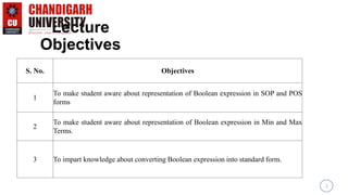


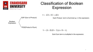


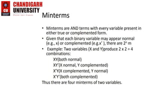

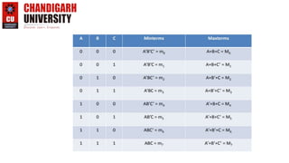
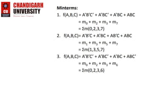
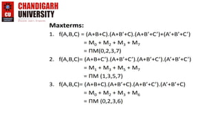


This document provides an introduction to representing Boolean expressions in Sum of Products (SOP) and Product of Sum (POS) forms. It defines SOP and POS, explaining that SOP multiplies product terms and POS sums max terms. It compares the two forms, noting differences in how variables are represented and the forms are constructed. Canonical SOP and POS forms are described as having all literals in each term. Minterms and maxterms are defined in relation to input variables. Course objectives and outcomes are listed for an Introduction to Electrical and Electronics Engineering course, covering fundamentals and circuit analysis.