Downloaded 72 times
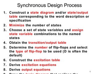
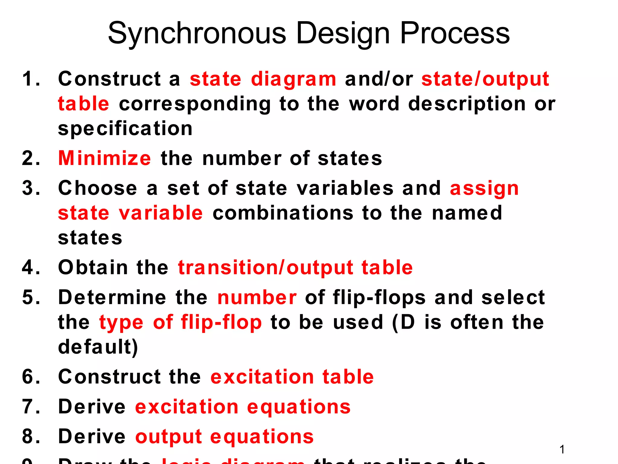
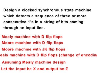
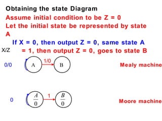
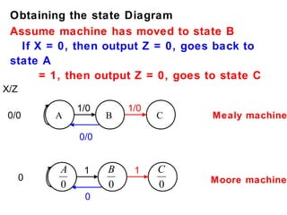
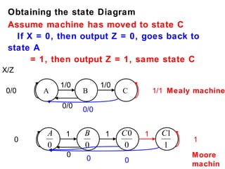
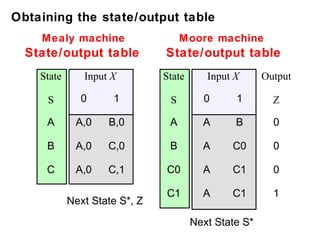
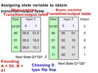
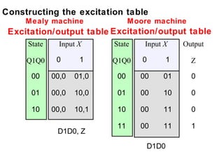
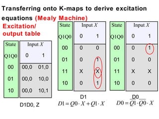
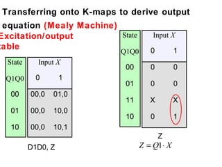
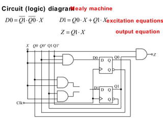
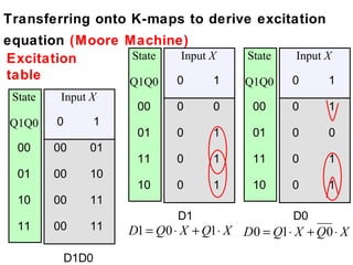
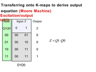
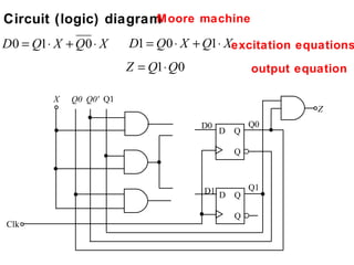
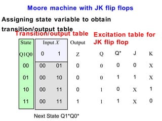
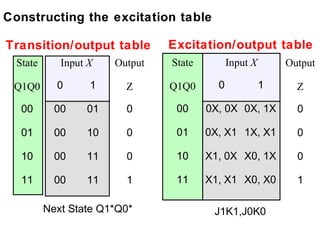
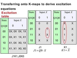
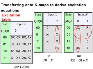
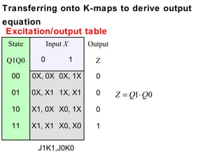
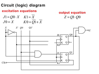
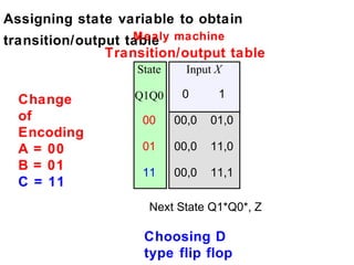
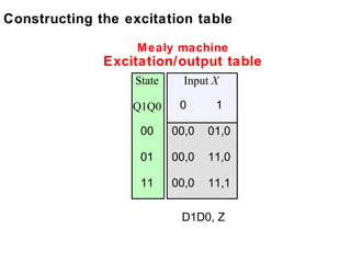
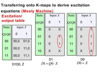
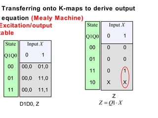
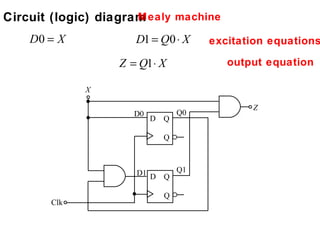
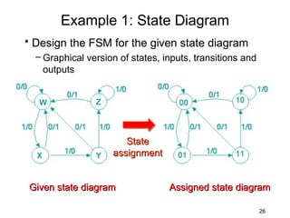
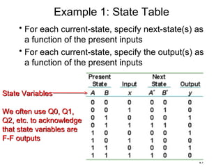
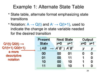
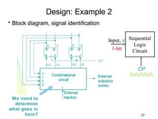
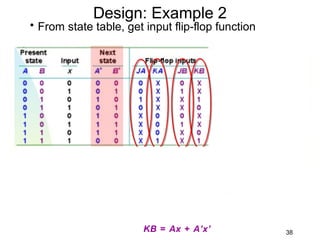
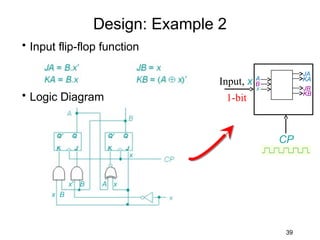
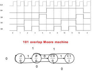
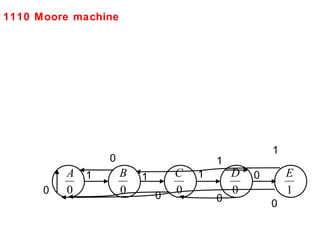

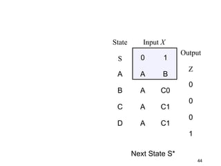
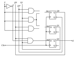
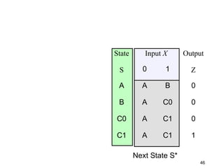

This document describes the process for designing a synchronous state machine using both Mealy and Moore machine approaches. The steps include constructing a state diagram and table, assigning state variables, deriving excitation and output equations, and implementing the design using D or JK flip-flops. An example 3-state machine is designed to detect 3 or more consecutive 1's in an input signal. The example walks through obtaining the state diagram and table, assigning states, and deriving the logic equations for both Mealy and Moore machine implementations.