Downloaded 504 times
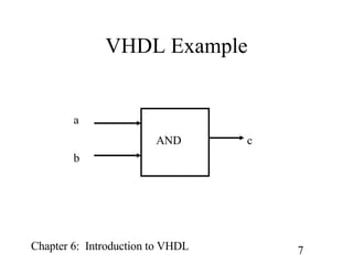
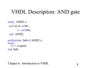
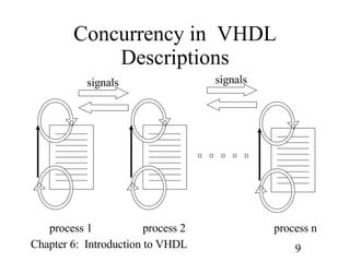


The document provides an introduction to VHDL including its origins, domains of description, abstraction levels, modeling styles, and examples of behavioral and structural descriptions. It discusses key VHDL concepts such as entities, architectures, concurrency, hierarchy, and modeling at different levels of abstraction using both behavioral and structural descriptions. Examples include behavioral descriptions of basic components like an AND gate, full adder, D flip-flop, and 4-to-1 multiplexer as well as structural descriptions of a 4-bit adder and 4-bit comparator.