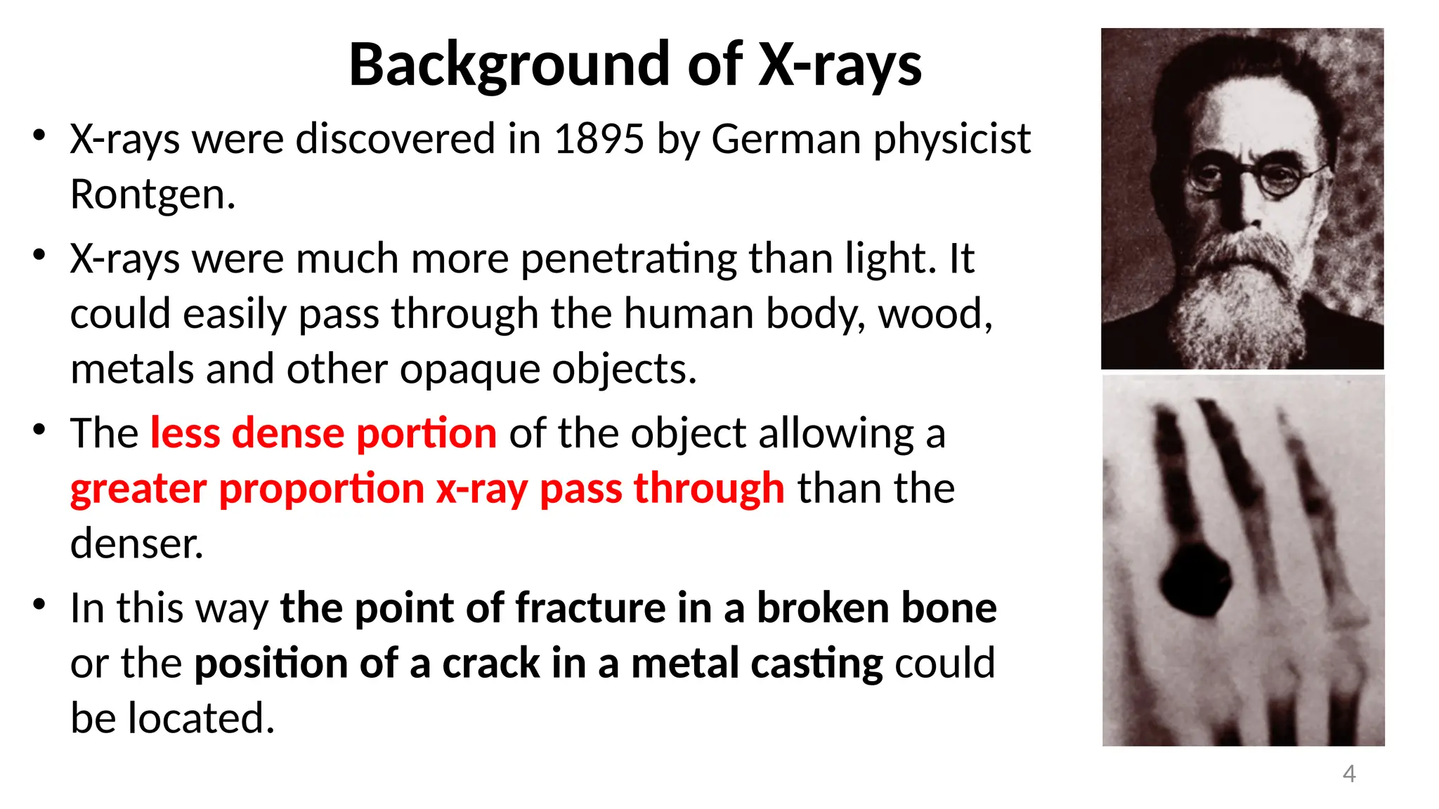
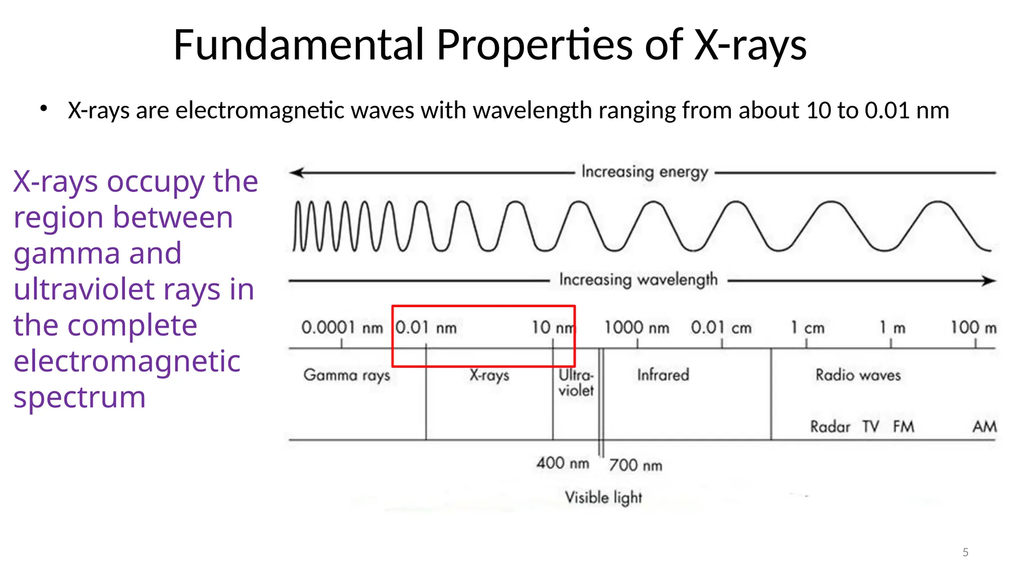
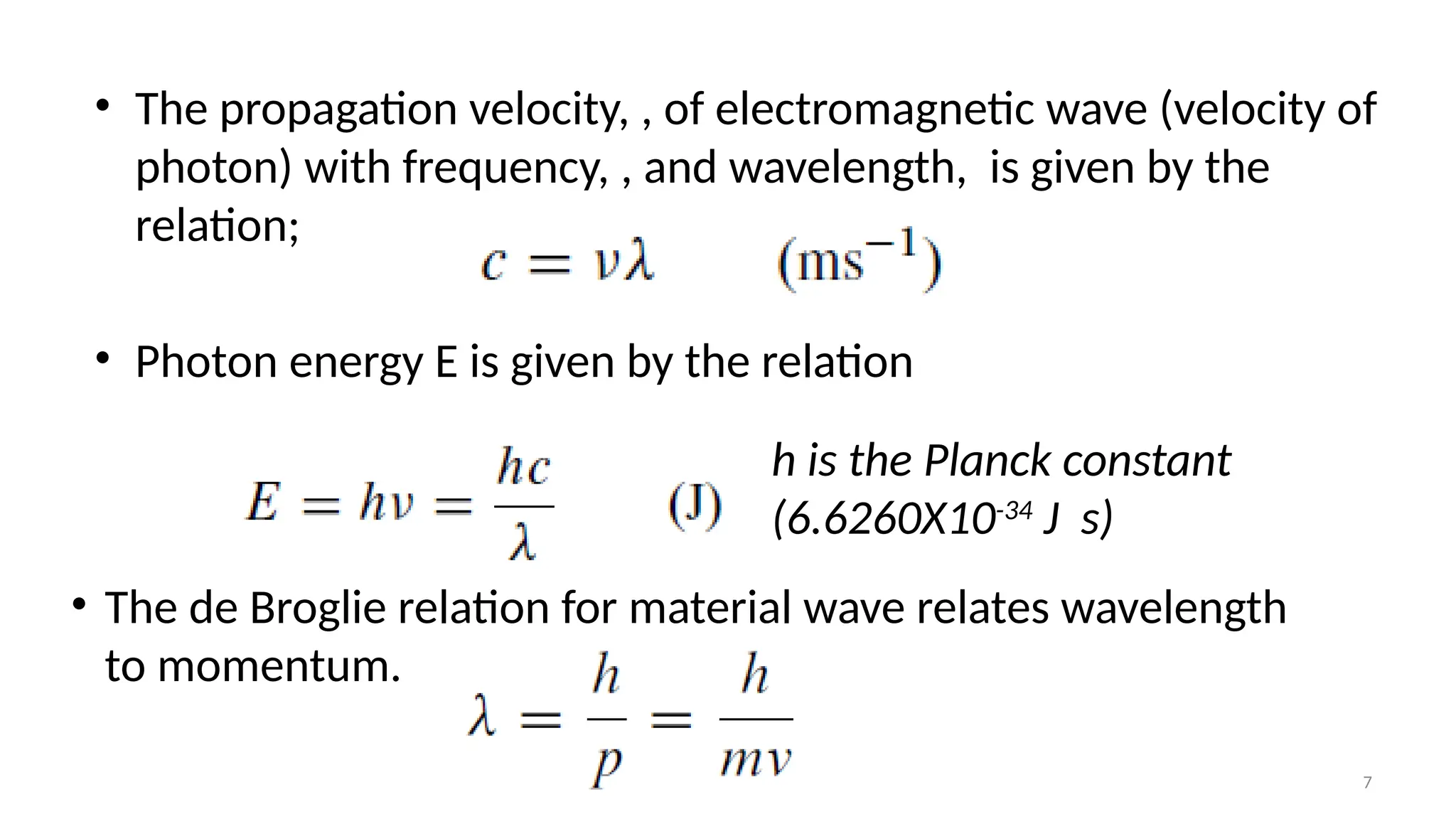
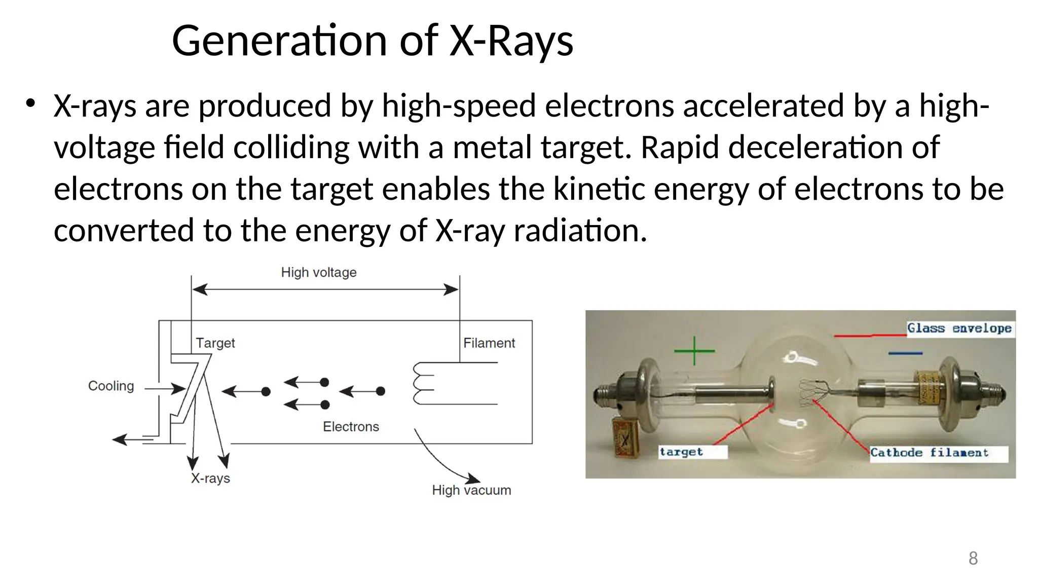
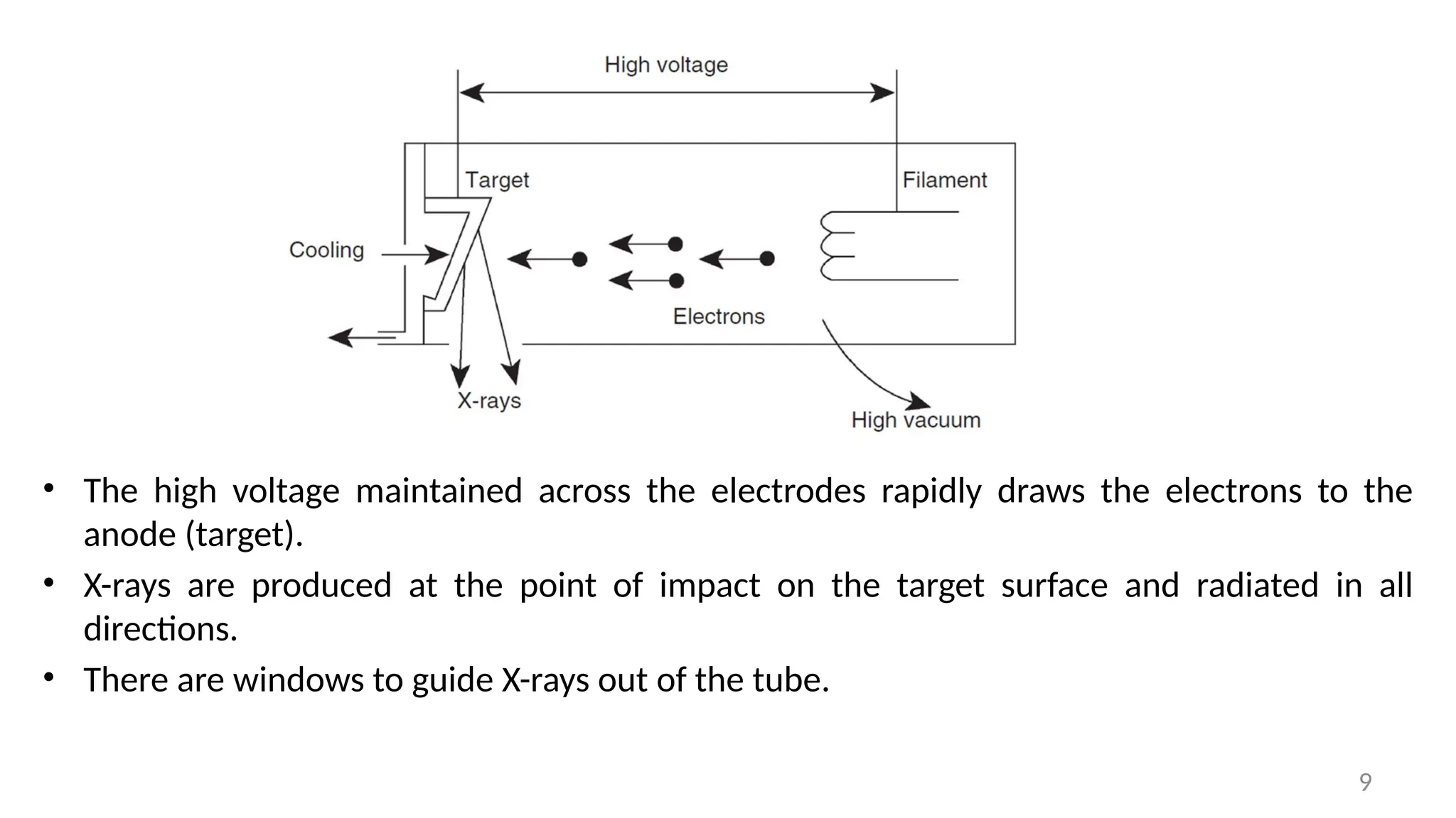
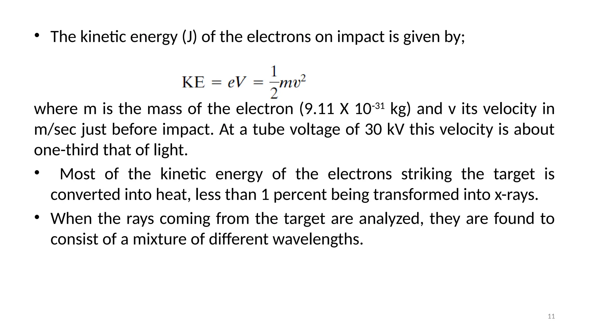
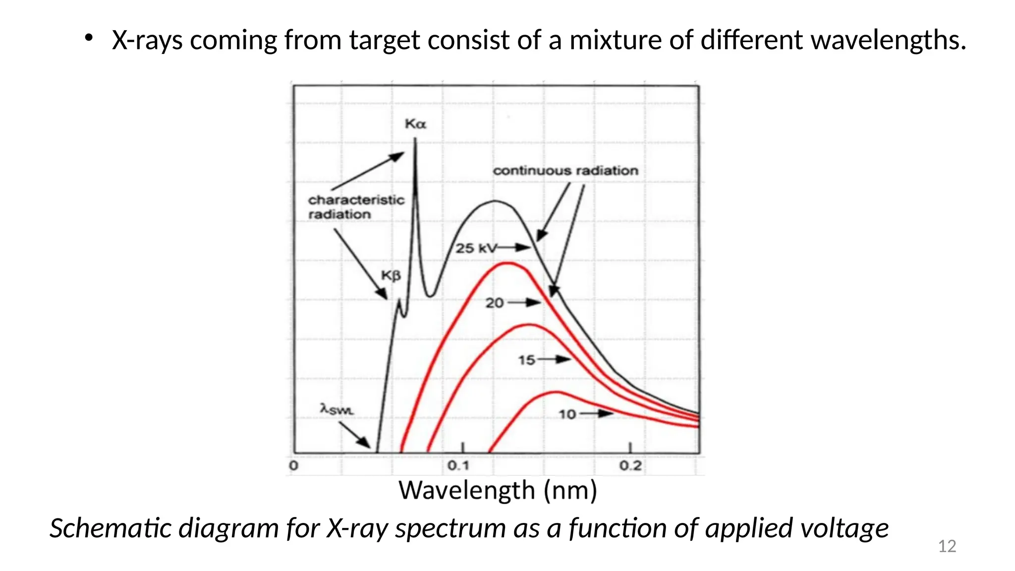
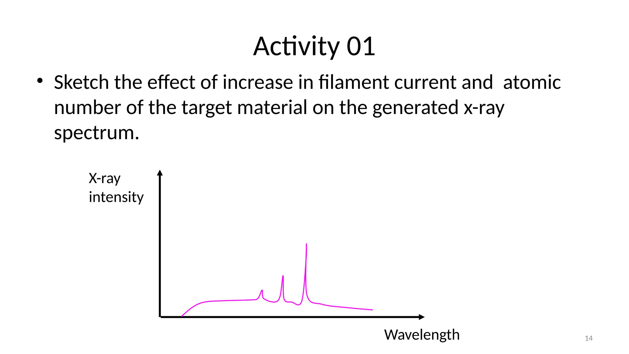
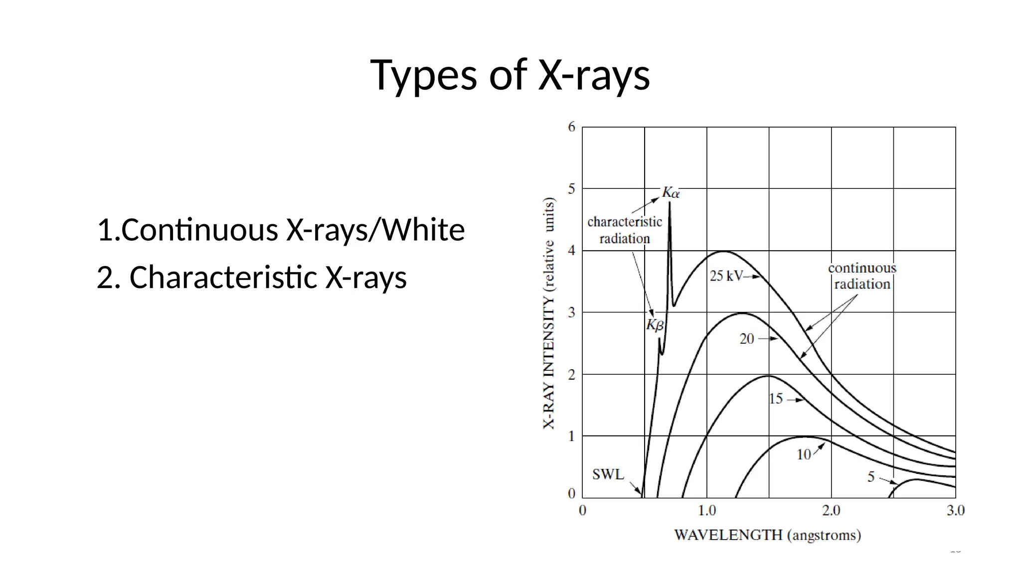
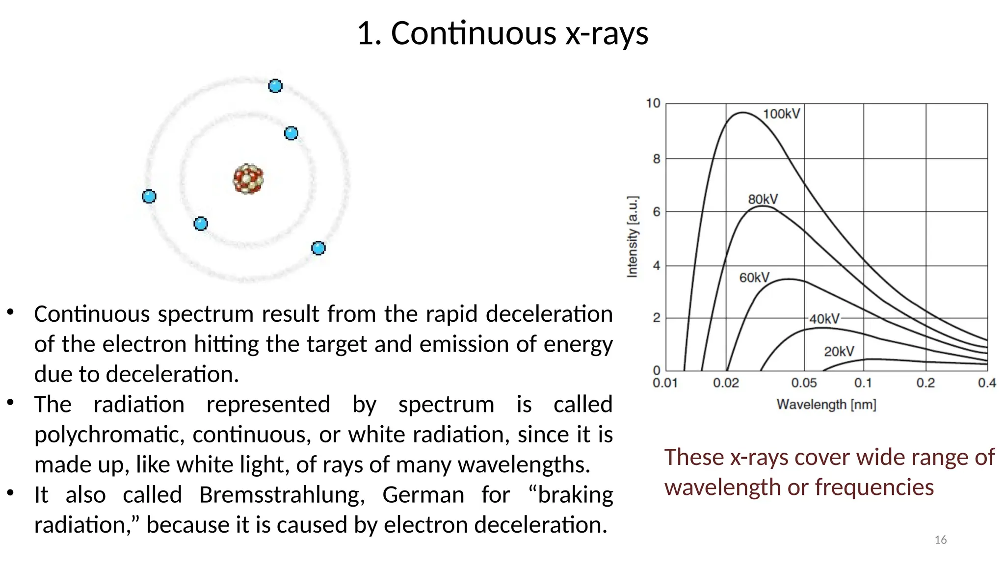
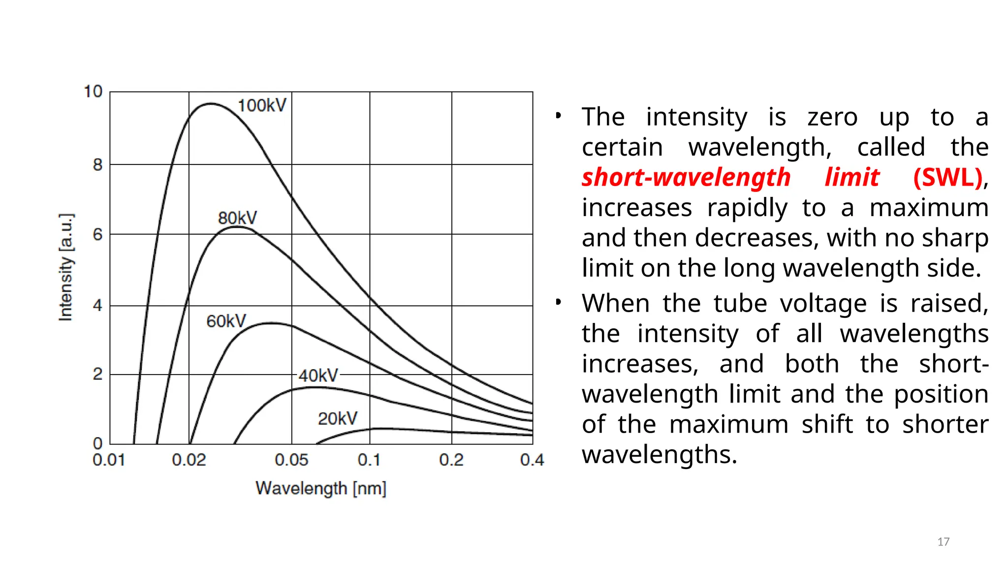
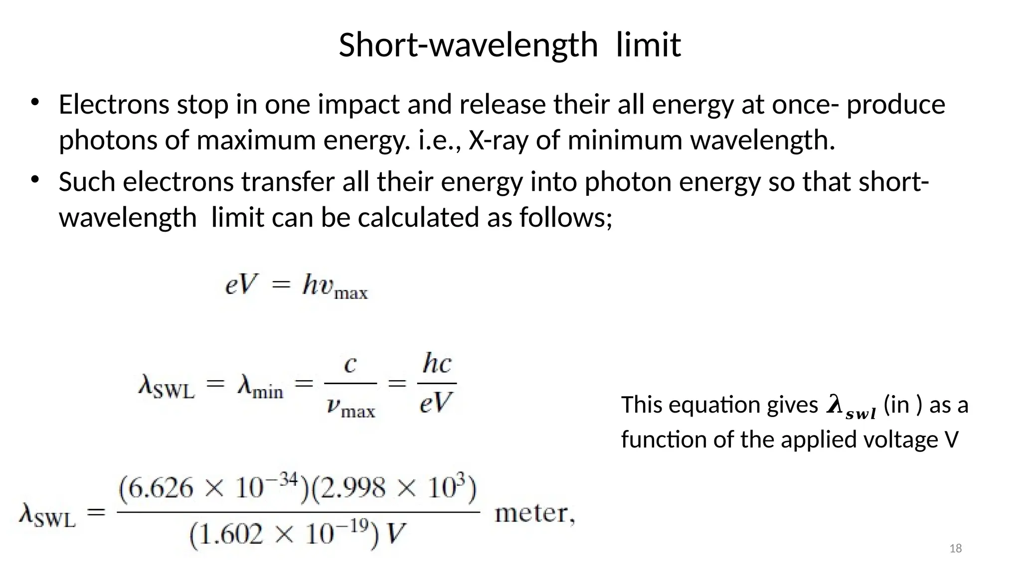
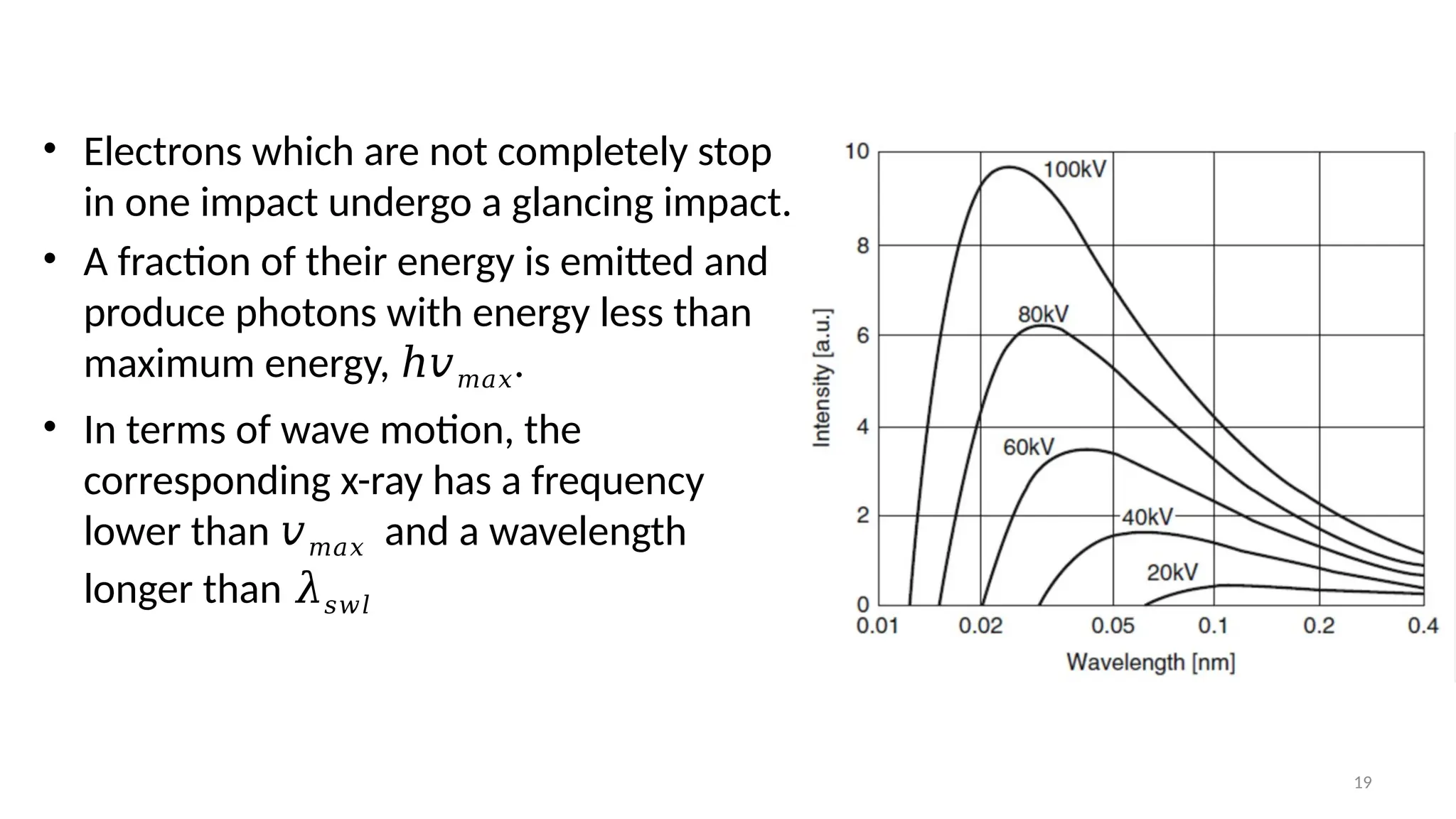
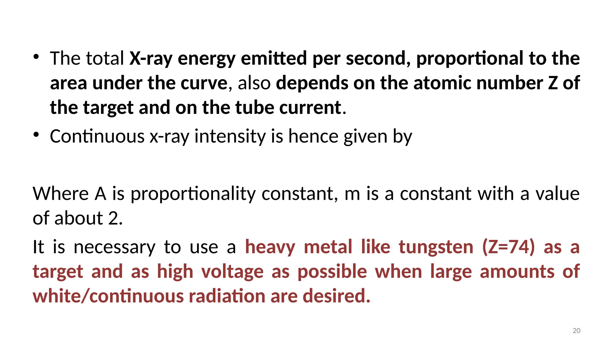
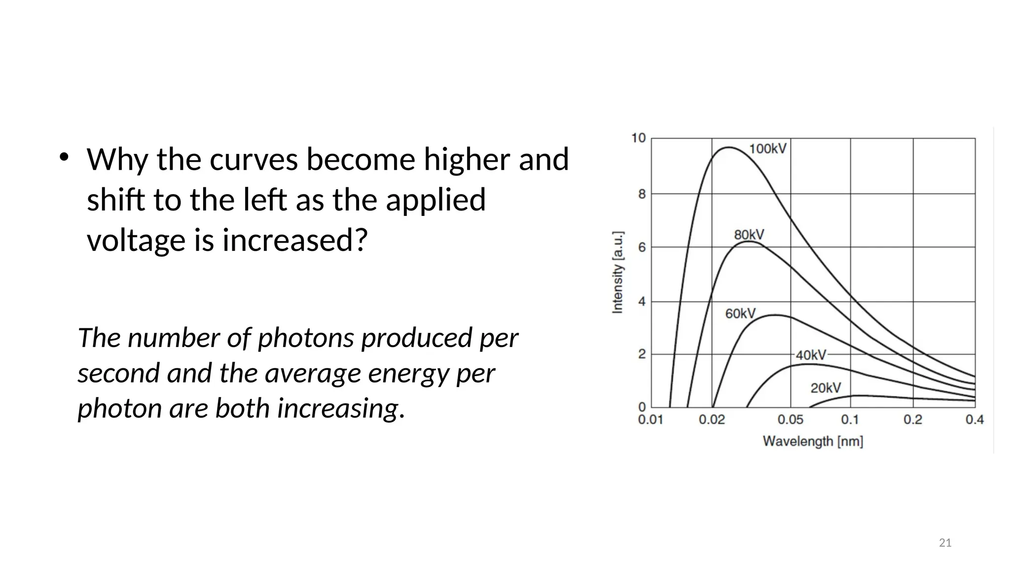
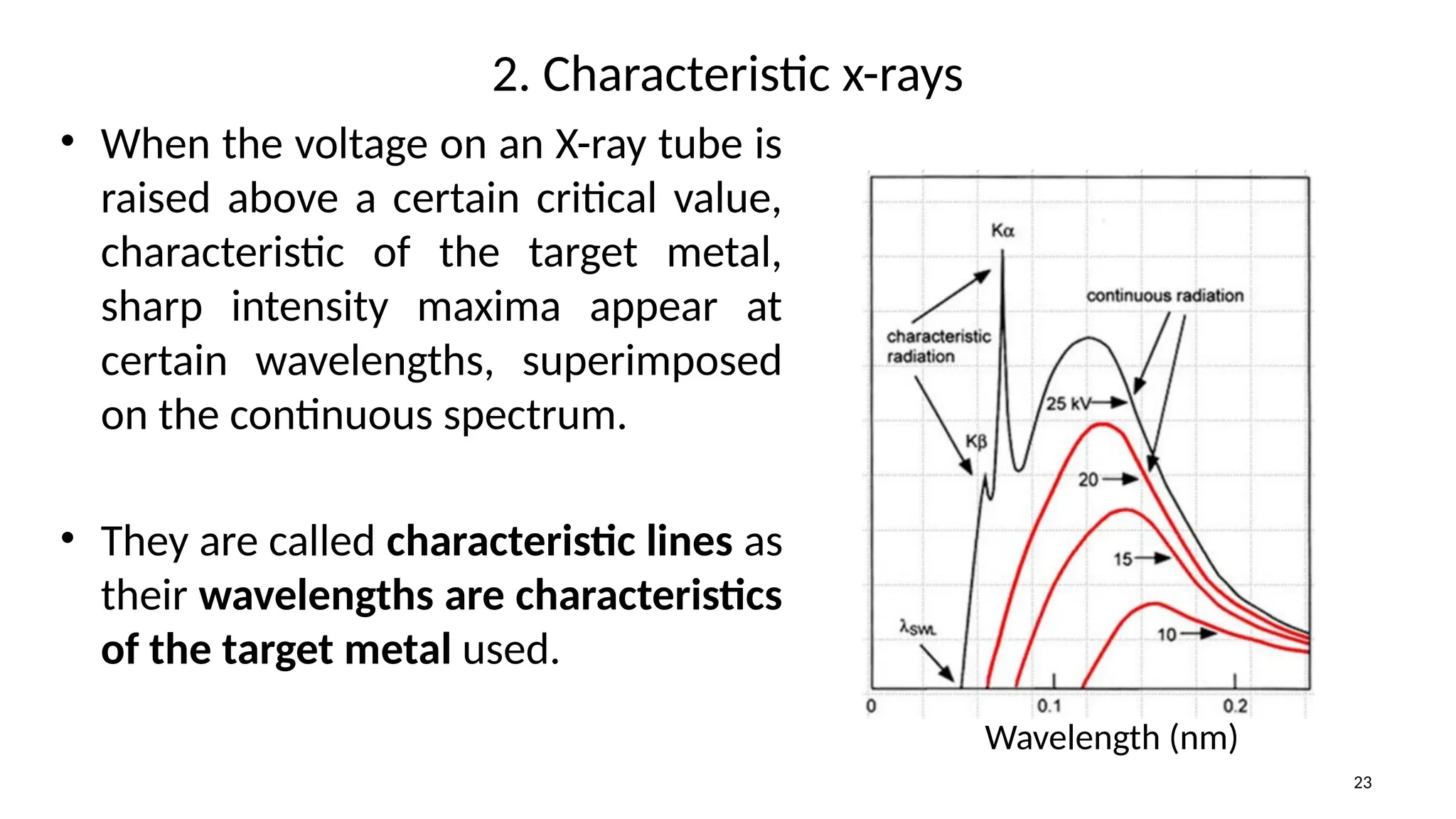
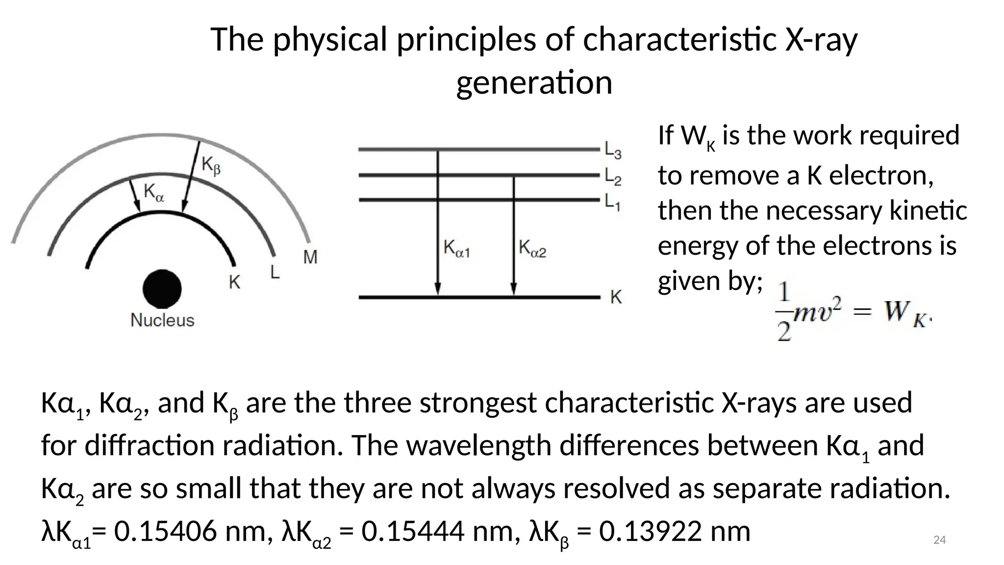
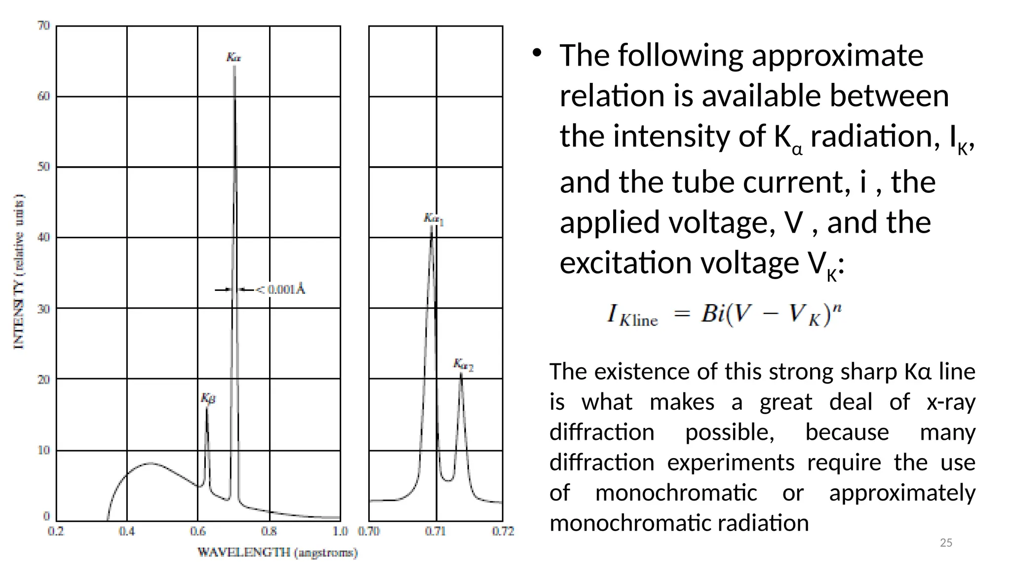
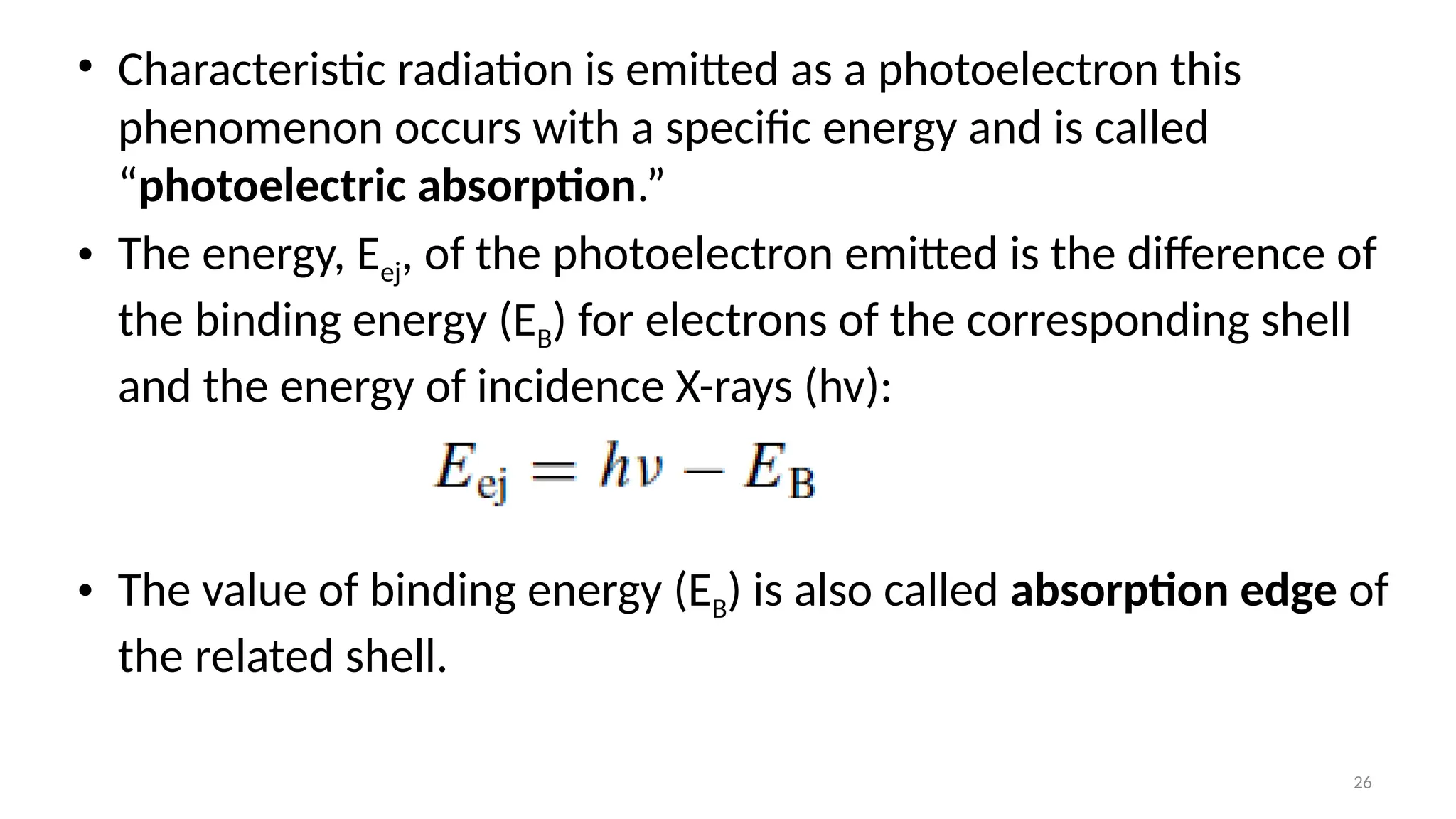
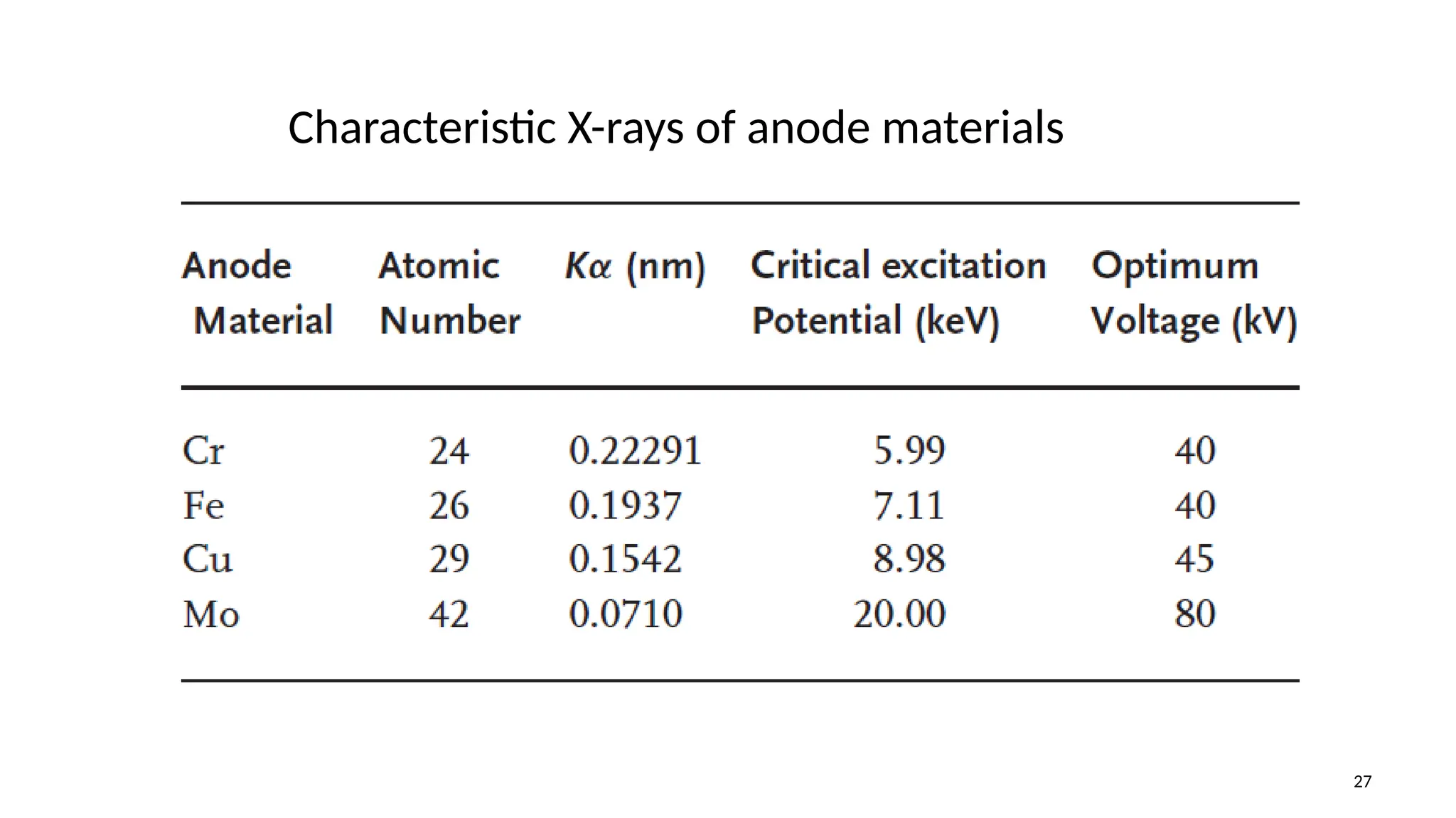
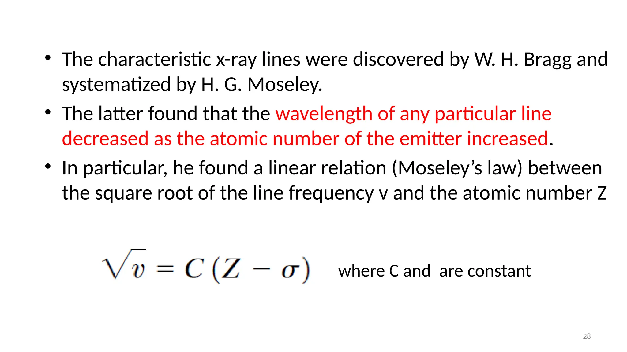
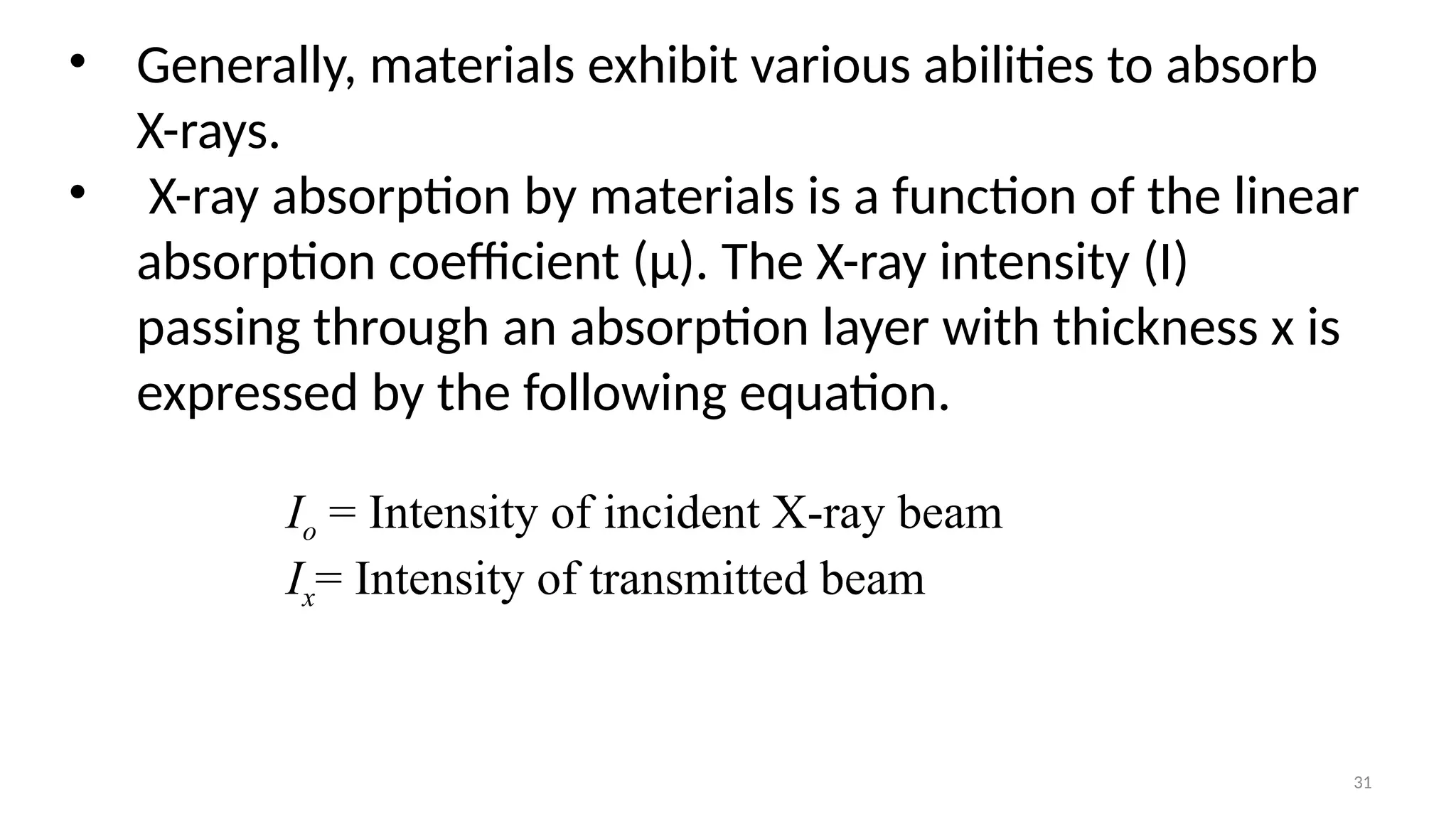
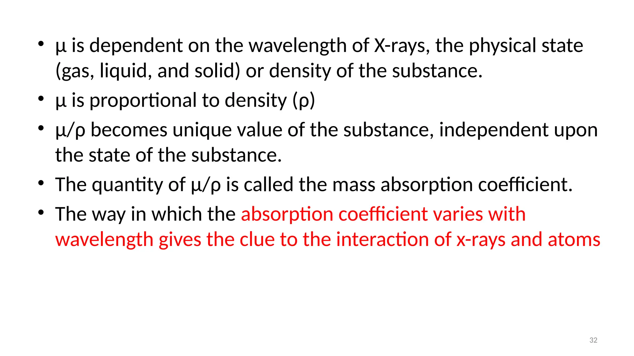
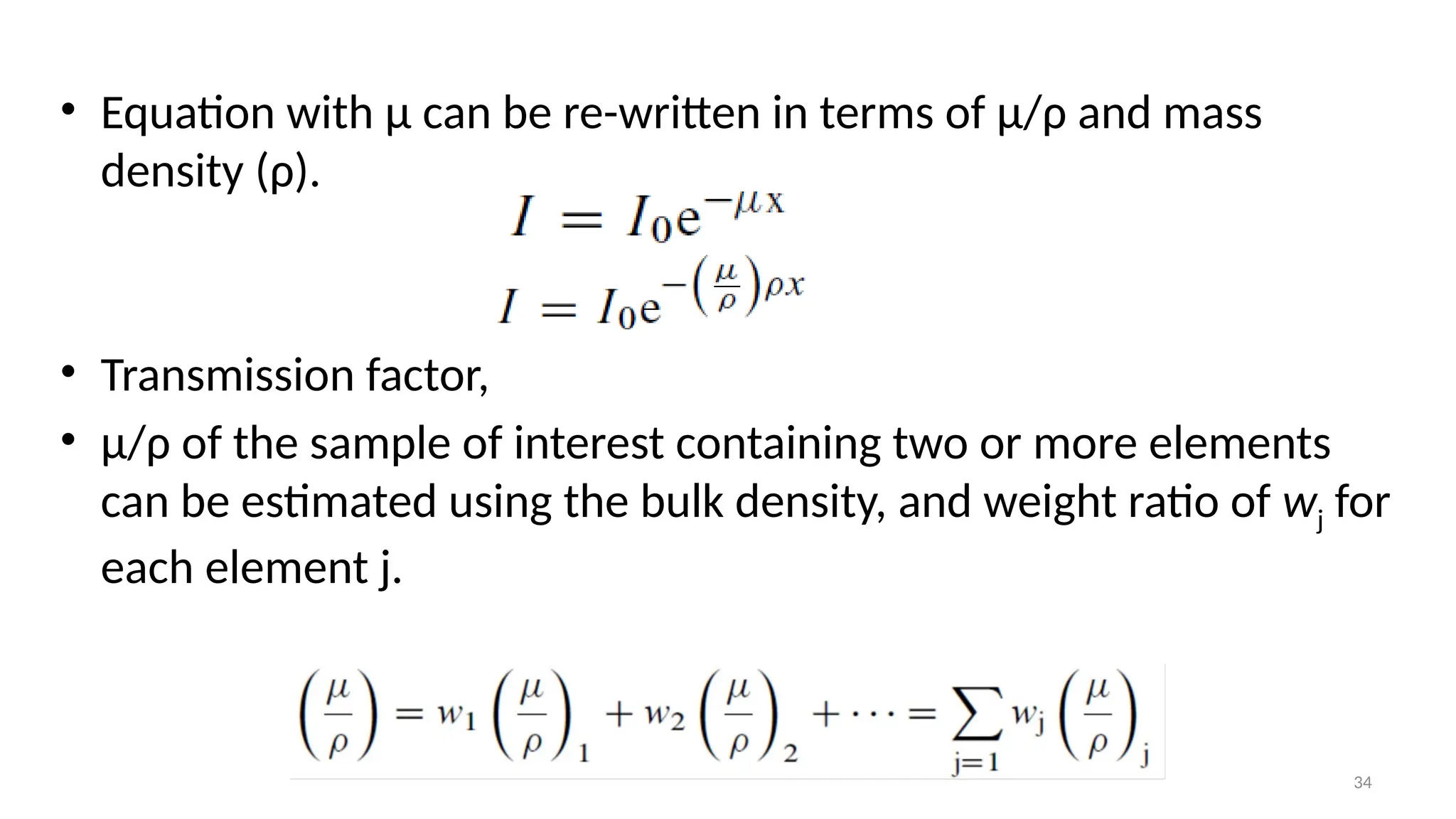
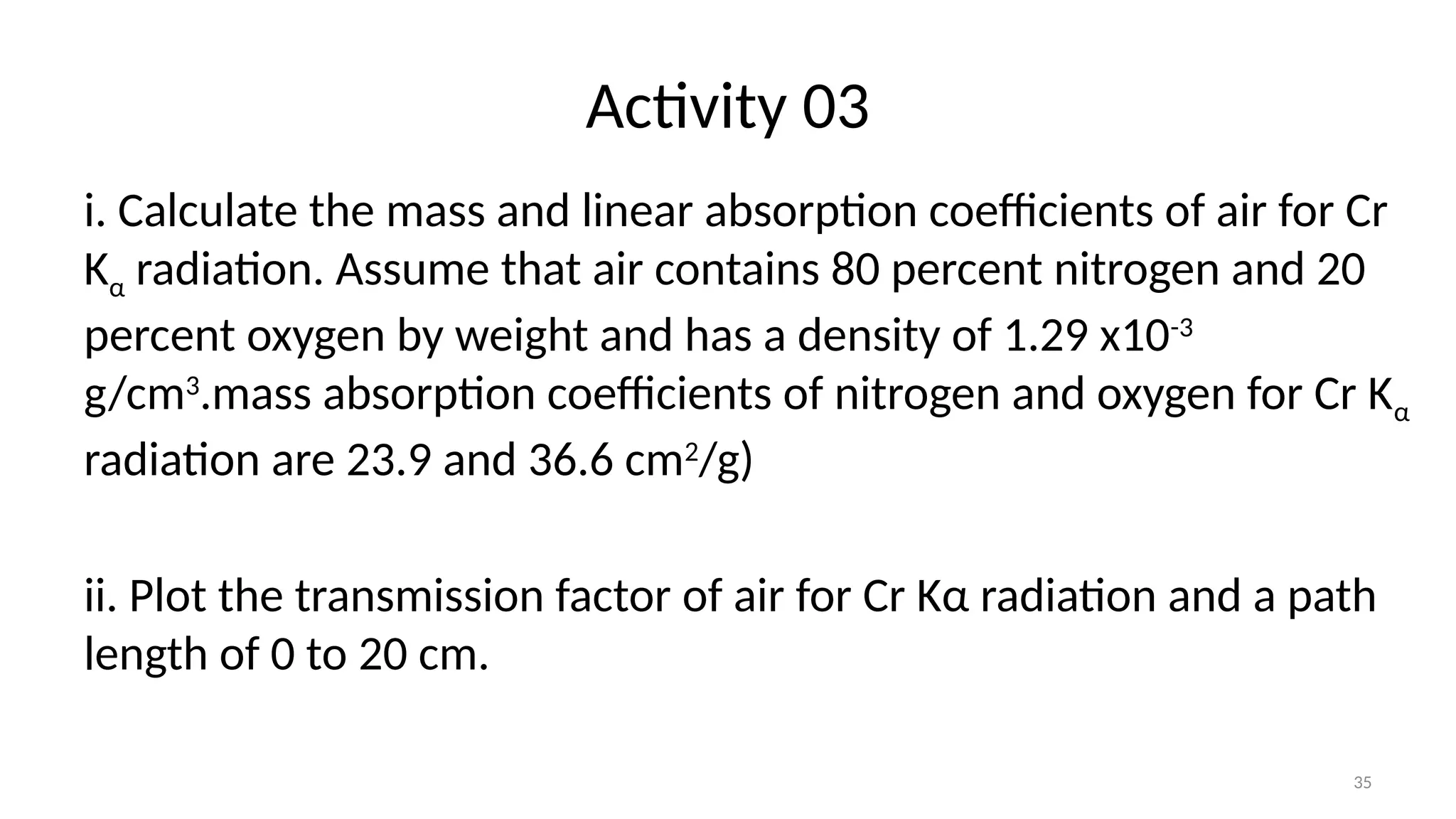
1
MT3054 - Characterization of Materials
L1- Fundamentals of X-rays
Prof. Galhenage A. Sewvandi
2
Introduction to Characterization of Materials
• In general terms, microstructural characterization is achieved
by allowing some form of probe to interact with a carefully
prepared specimen sample.
• The most commonly used probes are visible light, X-ray
radiation and a high energy electron beam.
• Once the probe has interacted with the sample, the scattered
or excited signal is collected and processed into a form where it
can be interpreted, either qualitatively or quantitatively.
Outline
• Background of X-rays
• Fundamental Properties of X-rays
• Generation of X-rays
• X-Ray Absorption
• Safety with X-Rays
3
• X-rays were discovered in 1895 by German physicist
Rontgen.
• X-rays were much more penetrating than light. It
could easily pass through the human body, wood,
metals and other opaque objects.
• The less dense portion of the object allowing a
greater proportion x-ray pass through than the
denser.
• In this way the point of fracture in a broken bone
or the position of a crack in a metal casting could
be located.
4
Background of X-rays
5
• X-rays are electromagnetic waves with wavelength ranging from about 10 to 0.01 nm
X-rays occupy the
region between
gamma and
ultraviolet rays in
the complete
electromagnetic
spectrum
Fundamental Properties of X-rays
6
• Electromagnetic radiation has been considered as wave motion
in accordance with classical theory.
• According to quantum theory, electromagnetic radiation can
also be considered as a stream of particles called quanta or
photons.
7
• The propagation velocity, , of electromagnetic wave (velocity of
photon) with frequency, , and wavelength, is given by the
relation;
• Photon energy E is given by the relation
h is the Planck constant
(6.6260X10⁻³⁴
J s)
• The de Broglie relation for material wave relates wavelength
to momentum.
Generation of X-Rays
• X-rays are produced by high-speed electrons accelerated by a high-
voltage field colliding with a metal target. Rapid deceleration of
electrons on the target enables the kinetic energy of electrons to be
converted to the energy of X-ray radiation.
8
• The high voltage maintained across the electrodes rapidly draws the electrons to the
anode (target).
• X-rays are produced at the point of impact on the target surface and radiated in all
directions.
• There are windows to guide X-rays out of the tube.
9
10
Sealed x-ray tube
Radiation outlet window
D8 X-ray Diffractometer
11
• The kinetic energy (J) of the electrons on impact is given by;
where m is the mass of the electron (9.11 X 10⁻³¹
kg) and v its velocity in
m/sec just before impact. At a tube voltage of 30 kV this velocity is about
one-third that of light.
• Most of the kinetic energy of the electrons striking the target is
converted into heat, less than 1 percent being transformed into x-rays.
• When the rays coming from the target are analyzed, they are found to
consist of a mixture of different wavelengths.
12
• X-rays coming from target consist of a mixture of different wavelengths.
Schematic diagram for X-ray spectrum as a function of applied voltage
13
• The variation of intensity with wavelength is depends on;
1. Applied voltage
2. Filament current
3. Atomic number of the target material.
14
Activity 01
• Sketch the effect of increase in filament current and atomic
number of the target material on the generated x-ray
spectrum.
X-ray
intensity
Wavelength
15
Types of X-rays
1.Continuous X-rays/White
2. Characteristic X-rays
16
These x-rays cover wide range of
wavelength or frequencies
1. Continuous x-rays
• Continuous spectrum result from the rapid deceleration
of the electron hitting the target and emission of energy
due to deceleration.
• The radiation represented by spectrum is called
polychromatic, continuous, or white radiation, since it is
made up, like white light, of rays of many wavelengths.
• It also called Bremsstrahlung, German for “braking
radiation,” because it is caused by electron deceleration.
17
• The intensity is zero up to a
certain wavelength, called the
short-wavelength limit (SWL),
increases rapidly to a maximum
and then decreases, with no sharp
limit on the long wavelength side.
• When the tube voltage is raised,
the intensity of all wavelengths
increases, and both the short-
wavelength limit and the position
of the maximum shift to shorter
wavelengths.
18
Short-wavelength limit
• Electrons stop in one impact and release their all energy at once- produce
photons of maximum energy. i.e., X-ray of minimum wavelength.
• Such electrons transfer all their energy into photon energy so that short-
wavelength limit can be calculated as follows;
This equation gives 𝝀𝒔𝒘𝒍 (in ) as a
function of the applied voltage V
19
• Electrons which are not completely stop
in one impact undergo a glancing impact.
• A fraction of their energy is emitted and
produce photons with energy less than
maximum energy, ℎ𝑣𝑚𝑎𝑥.
• In terms of wave motion, the
corresponding x-ray has a frequency
lower than 𝑣𝑚𝑎𝑥 and a wavelength
longer than 𝜆𝑠𝑤𝑙
20
• The total X-ray energy emitted per second, proportional to the
area under the curve, also depends on the atomic number Z of
the target and on the tube current.
• Continuous x-ray intensity is hence given by
Where A is proportionality constant, m is a constant with a value
of about 2.
It is necessary to use a heavy metal like tungsten (Z=74) as a
target and as high voltage as possible when large amounts of
white/continuous radiation are desired.
21
• Why the curves become higher and
shift to the left as the applied
voltage is increased?
The number of photons produced per
second and the average energy per
photon are both increasing.
22
Activity 02
• Calculate the kinetic energy and velocity with which the
electrons strike the target of an x-ray tube operated at 50 kV.
What is the short-wavelength limit of the continuous spectrum
emitted? mass of the electron = 9.11 X 10⁻³¹
kg, the Planck
constant is 6.6260X10⁻³⁴
J s)
2. Characteristic x-rays
• When the voltage on an X-ray tube is
raised above a certain critical value,
characteristic of the target metal,
sharp intensity maxima appear at
certain wavelengths, superimposed
on the continuous spectrum.
• They are called characteristic lines as
their wavelengths are characteristics
of the target metal used.
23
Wavelength (nm)
24
The physical principles of characteristic X-ray
generation
Kα1, Kα2, and Kβ are the three strongest characteristic X-rays are used
for diffraction radiation. The wavelength differences between Kα1 and
Kα2 are so small that they are not always resolved as separate radiation.
λKα1= 0.15406 nm, λKα2 = 0.15444 nm, λKβ = 0.13922 nm
If WK is the work required
to remove a K electron,
then the necessary kinetic
energy of the electrons is
given by;
25
• The following approximate
relation is available between
the intensity of Kα radiation, IK,
and the tube current, i , the
applied voltage, V , and the
excitation voltage VK:
The existence of this strong sharp Kα line
is what makes a great deal of x-ray
diffraction possible, because many
diffraction experiments require the use
of monochromatic or approximately
monochromatic radiation
26
• Characteristic radiation is emitted as a photoelectron this
phenomenon occurs with a specific energy and is called
“photoelectric absorption.”
• The energy, Eej, of the photoelectron emitted is the difference of
the binding energy (EB) for electrons of the corresponding shell
and the energy of incidence X-rays (hv):
• The value of binding energy (EB) is also called absorption edge of
the related shell.
27
Characteristic X-rays of anode materials
28
• The characteristic x-ray lines were discovered by W. H. Bragg and
systematized by H. G. Moseley.
• The latter found that the wavelength of any particular line
decreased as the atomic number of the emitter increased.
• In particular, he found a linear relation (Moseley’s law) between
the square root of the line frequency v and the atomic number Z
where C and are constant
29
• Moseley’s relation between,
and Z for two characteristic
lines.
30
Absorption of X-rays
• Further understanding of the electronic transitions which can occur in
atoms can be gained by considering the interaction of x-rays and atoms.
• When x-rays encounter any form of matter, they are partly transmitted
and partly absorbed.
• Röntgen established that the fractional decrease in the intensity I of an x-
ray beam as it passes through any homogeneous substance is
proportional to the distance traversed x.
31
• Generally, materials exhibit various abilities to absorb
X-rays.
• X-ray absorption by materials is a function of the linear
absorption coefficient (μ). The X-ray intensity (I)
passing through an absorption layer with thickness x is
expressed by the following equation.
Io = Intensity of incident X-ray beam
Ix= Intensity of transmitted beam
32
• μ is dependent on the wavelength of X-rays, the physical state
(gas, liquid, and solid) or density of the substance.
• μ is proportional to density (ρ)
• μ/ρ becomes unique value of the substance, independent upon
the state of the substance.
• The quantity of μ/ρ is called the mass absorption coefficient.
• The way in which the absorption coefficient varies with
wavelength gives the clue to the interaction of x-rays and atoms
33
Wavelength dependences of mass absorption coefficient of X-ray by La
34
• Equation with μ can be re-written in terms of μ/ρ and mass
density (ρ).
• Transmission factor,
• μ/ρ of the sample of interest containing two or more elements
can be estimated using the bulk density, and weight ratio of wj for
each element j.
35
Activity 03
i. Calculate the mass and linear absorption coefficients of air for Cr
Kα radiation. Assume that air contains 80 percent nitrogen and 20
percent oxygen by weight and has a density of 1.29 x10⁻³
g/cm3
.mass absorption coefficients of nitrogen and oxygen for Cr Kα
radiation are 23.9 and 36.6 cm2
/g)
ii. Plot the transmission factor of air for Cr Kα radiation and a path
length of 0 to 20 cm.
36
• Absorption of X-rays becomes small as
transmittance increases with increasing
energy (wavelength becomes shorter).
• However, if the incident X-ray energy
comes close to a specific value (or
wavelength), the photoelectric absorption
takes place by ejecting an electron in K-
shell and then discontinuous variation in
absorption is found.
• This specific energy (wavelength) is called
absorption edge.
37
• X-ray powder diffraction required monochromatic X-ray source.
• The beam from an X-ray tube operated at a high voltage contains
not only the strong Kα line but also the Kβ line and the continuous
spectrum.
• The intensity of these undesirable components should be
decreased relative to Kα line.
38
• The feature of the absorption edge can be used for X-ray
radiation filtering.
• We may select a filter material of which the absorption edge is
located at a wavelength slightly shorter than that of Kα
radiation.
• The filter material can effectively absorb Kβ and continuous X-
rays with wavelengths shorter than the absorption edge.
39
Filtering mechanism of X-ray radiation
40
• Excitation voltages calculation. To excite K radiation, for example,
in the target of an x-ray tube, the bombarding electrons must have
energy equal to WK.
where VK is the K excitation voltage
and λK is the K absorption edge
wavelength (in angstroms).
41
Activity 04
What voltage must be applied to a molybdenum-target
tube in order that the emitted x-rays excite K fluorescent
radiation from a piece of copper placed in the x-ray
beam? What is the wavelength of the fluorescent
radiation?
42
• DETECTION OF X-RAYS: to detect x-ray beams use fluorescent
screens, photographic film, and electronic detectors. More
recently image (storage) plates
• SAFETY PRECAUTIONS: The operator of x-ray apparatus is
exposed to two obvious dangers, electric shock and radiation
injury, but both of these hazards can be reduced to negligible
proportions by proper design of equipment and reasonable
care on the part of the user.
43
• Electric Shock
-The danger of electric shock is always present around high-
voltage apparatus.
-Shock-proof sealed X-tubes are also available.
44
• Radiation Hazard
-x-rays can kill human tissue; in fact, it is precisely this property which is utilized in x-
ray therapy for killing cancer cells
- The biological effects of x-rays include burns , radiation sickness and, genetic
mutations.
- Slight exposures to x-rays are not cumulative, but above a certain level called the
“tolerance dose,” they do have a cumulative effect and can produce permanent
injury.
- The x-rays used in diffraction are particularly harmful because they have relatively
long wavelengths and are therefore easily absorbed by exposed organs such as
the skin and eyes.
45
• Current generations of diffraction apparatus are designed to
have no open beam paths or to be operated in radiation
enclosures.
• Portable detectors, called radiation survey meters, are
available for surveying various areas around x-ray equipment
for possible radiation leaks.
• Apparatus should be checked for radiation leaks periodically
and whenever the instrument’s configuration is changed.
46
Extra Activities
1.Suppose that a nickel filter is required to produce an intensity ratio of Cu Kα to Cu Kβ of
100/1 in the filtered beam. Calculate the thickness of the filter and the transmission
factor for the Cu Kα line
2.Filters for Co K radiation are usually made of iron oxide (Fe2O3) powder rather than iron
foil. If a filter contains 5 mg Fe2O3 /cm2
, what is the transmission factor for the Co Kα line?
What is the intensity ratio of Co Kα to Co Kβ in the filtered beam?
Unfiltered intensity ratio of Cu Kα to Cu Kβ is 7.5. Mass absorption coefficients of CuKα and
Cu Kβ in Ni are 49.5 cm2
/g and 286 cm2
/g. Density of Ni is 8.9 g/cm3
. respectively.
Unfiltered intensity ratio of Co Kα to Co Kβ is 9.4. Mass absorption coefficients of CoKα and
Co Kβ in Fe and O are 56.2 cm2
/g , 17.44 cm2
/g and 12.85 cm2
/g , 345.5 cm2
/g,
respectively.
47
References
Elements of X-Ray Diffraction by B.D. Cullity S.R. Stock

L1-Fundamentals of X-ray refrferfrferfref

  • 1.
    1 MT3054 - Characterizationof Materials L1- Fundamentals of X-rays Prof. Galhenage A. Sewvandi
  • 2.
    2 Introduction to Characterizationof Materials • In general terms, microstructural characterization is achieved by allowing some form of probe to interact with a carefully prepared specimen sample. • The most commonly used probes are visible light, X-ray radiation and a high energy electron beam. • Once the probe has interacted with the sample, the scattered or excited signal is collected and processed into a form where it can be interpreted, either qualitatively or quantitatively.
  • 3.
    Outline • Background ofX-rays • Fundamental Properties of X-rays • Generation of X-rays • X-Ray Absorption • Safety with X-Rays 3
  • 4.
    • X-rays werediscovered in 1895 by German physicist Rontgen. • X-rays were much more penetrating than light. It could easily pass through the human body, wood, metals and other opaque objects. • The less dense portion of the object allowing a greater proportion x-ray pass through than the denser. • In this way the point of fracture in a broken bone or the position of a crack in a metal casting could be located. 4 Background of X-rays
  • 5.
    5 • X-rays areelectromagnetic waves with wavelength ranging from about 10 to 0.01 nm X-rays occupy the region between gamma and ultraviolet rays in the complete electromagnetic spectrum Fundamental Properties of X-rays
  • 6.
    6 • Electromagnetic radiationhas been considered as wave motion in accordance with classical theory. • According to quantum theory, electromagnetic radiation can also be considered as a stream of particles called quanta or photons.
  • 7.
    7 • The propagationvelocity, , of electromagnetic wave (velocity of photon) with frequency, , and wavelength, is given by the relation; • Photon energy E is given by the relation h is the Planck constant (6.6260X10⁻³⁴ J s) • The de Broglie relation for material wave relates wavelength to momentum.
  • 8.
    Generation of X-Rays •X-rays are produced by high-speed electrons accelerated by a high- voltage field colliding with a metal target. Rapid deceleration of electrons on the target enables the kinetic energy of electrons to be converted to the energy of X-ray radiation. 8
  • 9.
    • The highvoltage maintained across the electrodes rapidly draws the electrons to the anode (target). • X-rays are produced at the point of impact on the target surface and radiated in all directions. • There are windows to guide X-rays out of the tube. 9
  • 10.
    10 Sealed x-ray tube Radiationoutlet window D8 X-ray Diffractometer
  • 11.
    11 • The kineticenergy (J) of the electrons on impact is given by; where m is the mass of the electron (9.11 X 10⁻³¹ kg) and v its velocity in m/sec just before impact. At a tube voltage of 30 kV this velocity is about one-third that of light. • Most of the kinetic energy of the electrons striking the target is converted into heat, less than 1 percent being transformed into x-rays. • When the rays coming from the target are analyzed, they are found to consist of a mixture of different wavelengths.
  • 12.
    12 • X-rays comingfrom target consist of a mixture of different wavelengths. Schematic diagram for X-ray spectrum as a function of applied voltage
  • 13.
    13 • The variationof intensity with wavelength is depends on; 1. Applied voltage 2. Filament current 3. Atomic number of the target material.
  • 14.
    14 Activity 01 • Sketchthe effect of increase in filament current and atomic number of the target material on the generated x-ray spectrum. X-ray intensity Wavelength
  • 15.
    15 Types of X-rays 1.ContinuousX-rays/White 2. Characteristic X-rays
  • 16.
    16 These x-rays coverwide range of wavelength or frequencies 1. Continuous x-rays • Continuous spectrum result from the rapid deceleration of the electron hitting the target and emission of energy due to deceleration. • The radiation represented by spectrum is called polychromatic, continuous, or white radiation, since it is made up, like white light, of rays of many wavelengths. • It also called Bremsstrahlung, German for “braking radiation,” because it is caused by electron deceleration.
  • 17.
    17 • The intensityis zero up to a certain wavelength, called the short-wavelength limit (SWL), increases rapidly to a maximum and then decreases, with no sharp limit on the long wavelength side. • When the tube voltage is raised, the intensity of all wavelengths increases, and both the short- wavelength limit and the position of the maximum shift to shorter wavelengths.
  • 18.
    18 Short-wavelength limit • Electronsstop in one impact and release their all energy at once- produce photons of maximum energy. i.e., X-ray of minimum wavelength. • Such electrons transfer all their energy into photon energy so that short- wavelength limit can be calculated as follows; This equation gives 𝝀𝒔𝒘𝒍 (in ) as a function of the applied voltage V
  • 19.
    19 • Electrons whichare not completely stop in one impact undergo a glancing impact. • A fraction of their energy is emitted and produce photons with energy less than maximum energy, ℎ𝑣𝑚𝑎𝑥. • In terms of wave motion, the corresponding x-ray has a frequency lower than 𝑣𝑚𝑎𝑥 and a wavelength longer than 𝜆𝑠𝑤𝑙
  • 20.
    20 • The totalX-ray energy emitted per second, proportional to the area under the curve, also depends on the atomic number Z of the target and on the tube current. • Continuous x-ray intensity is hence given by Where A is proportionality constant, m is a constant with a value of about 2. It is necessary to use a heavy metal like tungsten (Z=74) as a target and as high voltage as possible when large amounts of white/continuous radiation are desired.
  • 21.
    21 • Why thecurves become higher and shift to the left as the applied voltage is increased? The number of photons produced per second and the average energy per photon are both increasing.
  • 22.
    22 Activity 02 • Calculatethe kinetic energy and velocity with which the electrons strike the target of an x-ray tube operated at 50 kV. What is the short-wavelength limit of the continuous spectrum emitted? mass of the electron = 9.11 X 10⁻³¹ kg, the Planck constant is 6.6260X10⁻³⁴ J s)
  • 23.
    2. Characteristic x-rays •When the voltage on an X-ray tube is raised above a certain critical value, characteristic of the target metal, sharp intensity maxima appear at certain wavelengths, superimposed on the continuous spectrum. • They are called characteristic lines as their wavelengths are characteristics of the target metal used. 23 Wavelength (nm)
  • 24.
    24 The physical principlesof characteristic X-ray generation Kα1, Kα2, and Kβ are the three strongest characteristic X-rays are used for diffraction radiation. The wavelength differences between Kα1 and Kα2 are so small that they are not always resolved as separate radiation. λKα1= 0.15406 nm, λKα2 = 0.15444 nm, λKβ = 0.13922 nm If WK is the work required to remove a K electron, then the necessary kinetic energy of the electrons is given by;
  • 25.
    25 • The followingapproximate relation is available between the intensity of Kα radiation, IK, and the tube current, i , the applied voltage, V , and the excitation voltage VK: The existence of this strong sharp Kα line is what makes a great deal of x-ray diffraction possible, because many diffraction experiments require the use of monochromatic or approximately monochromatic radiation
  • 26.
    26 • Characteristic radiationis emitted as a photoelectron this phenomenon occurs with a specific energy and is called “photoelectric absorption.” • The energy, Eej, of the photoelectron emitted is the difference of the binding energy (EB) for electrons of the corresponding shell and the energy of incidence X-rays (hv): • The value of binding energy (EB) is also called absorption edge of the related shell.
  • 27.
  • 28.
    28 • The characteristicx-ray lines were discovered by W. H. Bragg and systematized by H. G. Moseley. • The latter found that the wavelength of any particular line decreased as the atomic number of the emitter increased. • In particular, he found a linear relation (Moseley’s law) between the square root of the line frequency v and the atomic number Z where C and are constant
  • 29.
    29 • Moseley’s relationbetween, and Z for two characteristic lines.
  • 30.
    30 Absorption of X-rays •Further understanding of the electronic transitions which can occur in atoms can be gained by considering the interaction of x-rays and atoms. • When x-rays encounter any form of matter, they are partly transmitted and partly absorbed. • Röntgen established that the fractional decrease in the intensity I of an x- ray beam as it passes through any homogeneous substance is proportional to the distance traversed x.
  • 31.
    31 • Generally, materialsexhibit various abilities to absorb X-rays. • X-ray absorption by materials is a function of the linear absorption coefficient (μ). The X-ray intensity (I) passing through an absorption layer with thickness x is expressed by the following equation. Io = Intensity of incident X-ray beam Ix= Intensity of transmitted beam
  • 32.
    32 • μ isdependent on the wavelength of X-rays, the physical state (gas, liquid, and solid) or density of the substance. • μ is proportional to density (ρ) • μ/ρ becomes unique value of the substance, independent upon the state of the substance. • The quantity of μ/ρ is called the mass absorption coefficient. • The way in which the absorption coefficient varies with wavelength gives the clue to the interaction of x-rays and atoms
  • 33.
    33 Wavelength dependences ofmass absorption coefficient of X-ray by La
  • 34.
    34 • Equation withμ can be re-written in terms of μ/ρ and mass density (ρ). • Transmission factor, • μ/ρ of the sample of interest containing two or more elements can be estimated using the bulk density, and weight ratio of wj for each element j.
  • 35.
    35 Activity 03 i. Calculatethe mass and linear absorption coefficients of air for Cr Kα radiation. Assume that air contains 80 percent nitrogen and 20 percent oxygen by weight and has a density of 1.29 x10⁻³ g/cm3 .mass absorption coefficients of nitrogen and oxygen for Cr Kα radiation are 23.9 and 36.6 cm2 /g) ii. Plot the transmission factor of air for Cr Kα radiation and a path length of 0 to 20 cm.
  • 36.
    36 • Absorption ofX-rays becomes small as transmittance increases with increasing energy (wavelength becomes shorter). • However, if the incident X-ray energy comes close to a specific value (or wavelength), the photoelectric absorption takes place by ejecting an electron in K- shell and then discontinuous variation in absorption is found. • This specific energy (wavelength) is called absorption edge.
  • 37.
    37 • X-ray powderdiffraction required monochromatic X-ray source. • The beam from an X-ray tube operated at a high voltage contains not only the strong Kα line but also the Kβ line and the continuous spectrum. • The intensity of these undesirable components should be decreased relative to Kα line.
  • 38.
    38 • The featureof the absorption edge can be used for X-ray radiation filtering. • We may select a filter material of which the absorption edge is located at a wavelength slightly shorter than that of Kα radiation. • The filter material can effectively absorb Kβ and continuous X- rays with wavelengths shorter than the absorption edge.
  • 39.
  • 40.
    40 • Excitation voltagescalculation. To excite K radiation, for example, in the target of an x-ray tube, the bombarding electrons must have energy equal to WK. where VK is the K excitation voltage and λK is the K absorption edge wavelength (in angstroms).
  • 41.
    41 Activity 04 What voltagemust be applied to a molybdenum-target tube in order that the emitted x-rays excite K fluorescent radiation from a piece of copper placed in the x-ray beam? What is the wavelength of the fluorescent radiation?
  • 42.
    42 • DETECTION OFX-RAYS: to detect x-ray beams use fluorescent screens, photographic film, and electronic detectors. More recently image (storage) plates • SAFETY PRECAUTIONS: The operator of x-ray apparatus is exposed to two obvious dangers, electric shock and radiation injury, but both of these hazards can be reduced to negligible proportions by proper design of equipment and reasonable care on the part of the user.
  • 43.
    43 • Electric Shock -Thedanger of electric shock is always present around high- voltage apparatus. -Shock-proof sealed X-tubes are also available.
  • 44.
    44 • Radiation Hazard -x-rayscan kill human tissue; in fact, it is precisely this property which is utilized in x- ray therapy for killing cancer cells - The biological effects of x-rays include burns , radiation sickness and, genetic mutations. - Slight exposures to x-rays are not cumulative, but above a certain level called the “tolerance dose,” they do have a cumulative effect and can produce permanent injury. - The x-rays used in diffraction are particularly harmful because they have relatively long wavelengths and are therefore easily absorbed by exposed organs such as the skin and eyes.
  • 45.
    45 • Current generationsof diffraction apparatus are designed to have no open beam paths or to be operated in radiation enclosures. • Portable detectors, called radiation survey meters, are available for surveying various areas around x-ray equipment for possible radiation leaks. • Apparatus should be checked for radiation leaks periodically and whenever the instrument’s configuration is changed.
  • 46.
    46 Extra Activities 1.Suppose thata nickel filter is required to produce an intensity ratio of Cu Kα to Cu Kβ of 100/1 in the filtered beam. Calculate the thickness of the filter and the transmission factor for the Cu Kα line 2.Filters for Co K radiation are usually made of iron oxide (Fe2O3) powder rather than iron foil. If a filter contains 5 mg Fe2O3 /cm2 , what is the transmission factor for the Co Kα line? What is the intensity ratio of Co Kα to Co Kβ in the filtered beam? Unfiltered intensity ratio of Cu Kα to Cu Kβ is 7.5. Mass absorption coefficients of CuKα and Cu Kβ in Ni are 49.5 cm2 /g and 286 cm2 /g. Density of Ni is 8.9 g/cm3 . respectively. Unfiltered intensity ratio of Co Kα to Co Kβ is 9.4. Mass absorption coefficients of CoKα and Co Kβ in Fe and O are 56.2 cm2 /g , 17.44 cm2 /g and 12.85 cm2 /g , 345.5 cm2 /g, respectively.
  • 47.
    47 References Elements of X-RayDiffraction by B.D. Cullity S.R. Stock