This manual summarizes the following:
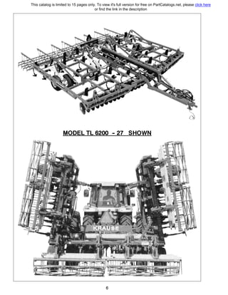
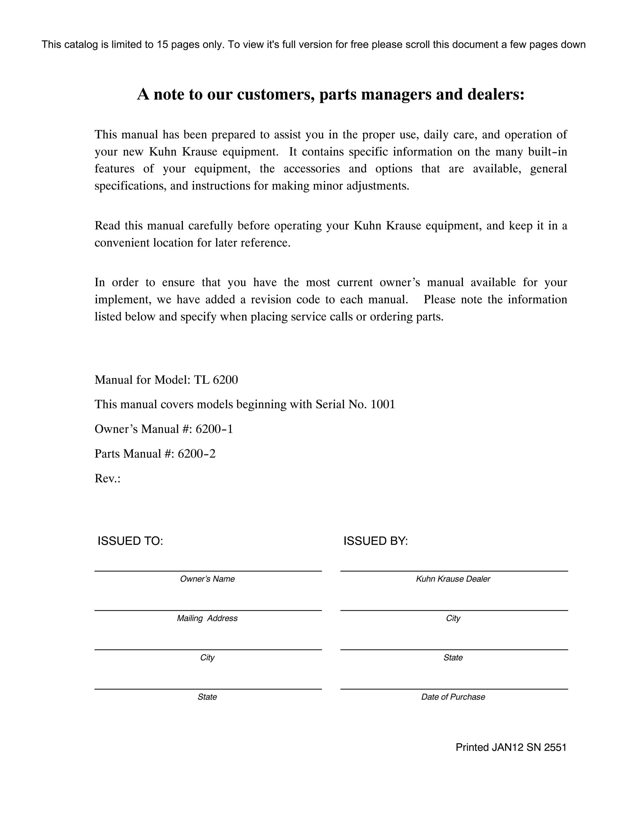
- It provides instructions for proper use, daily care, and operation of Kuhn Krause equipment.
- It contains information on built-in features, available accessories and options, general specifications, and instructions for minor adjustments.
- Customers should read this manual carefully before using their Kuhn Krause equipment and keep it handy for future reference.

![KUHN KRAUSE WARRANTY STATEMENT
(Kuhn Krause Serial Numbered Wholegoods purchased subsequent to May 1, 2008)
Note: This warranty is limited to the equipment and parts sold in North America and all
warranty work must be accomplished by a Kuhn Krause, Inc. Authorized Service
Center rated to perform maintenance on Kuhn Krause Products.
A. KUHN KRAUSE, INC. (“KRAUSE”) LIMITED WARRANTY.
(1) Subject to the limitations and conditions hereinafter set forth, Kuhn Krause warrants, at the time of
delivery by Kuhn Krause to be free from (i) defects in materials or workmanship, and (ii) defects in
design that in the view of the state of the art as of the date of manufacture should have been foreseen
provided, however, that the defect must be discovered and reported to Kuhn Krause within the periods
specified as follows. For a period of one year all new serial numbered production agricultural units
covered by this warranty; for a period of thirty--six (36) months the tongue weldment, center frame
weldment, wing frame weldments, disc harrow gang bearings and K--Tine field cultivator shanks.
(2) Kuhn Krause does not warrant disc blades, shanks, hydraulic cylinders, accessories and other parts
not manufactured by it, but supplied with or as a part of its products. Kuhn Krause will, however,
obtain and pass on any adjustments provided by the manufacturers of such parts under these
manufacturer’s warranties. Tires supplied on Kuhn Krause products, will be warranted by the tire
manufacturer’s retail outlets.
(3) The entire extent of Kuhn Krause’s liability shall be limited to that of either reimbursing Buyer for
its costs of purchasing a rebuilt, over--hauled or repaired part from either Kuhn Krause or a proper
Kuhn Krause Authorized Service Center or, at Kuhn Krause’s election, reimbursing buyer for its costs
of having the part repaired at a proper Kuhn Krause Authorized Service Center. If Kuhn Krause elects
not to repair the part and if neither a rebuilt, over--hauled or repaired part is, in Kuhn Krause’s
opinion, timely available then Kuhn Krause will reimburse buyer for its costs of purchasing a new part
from either Kuhn Krause or a proper Kuhn Krause Authorized Service Center. The labor necessary
to remove from the product such part or parts and to install in the product such part or parts, as well
as any repair made as the result of improper installations by Kuhn Krause, shall be covered by this
warranty, provided the work is performed at a proper Kuhn Krause Authorized Service Center.K If
return of the defective part is required, it must be returned shipping prepaid to Kuhn Krause, Inc.
Kuhn Krause’s limited warranty will apply to any part repaired or replaced by a proper Kuhn Krause
Authorized Service Center pursuant to Kuhn Krause’s Limited Warranty: however, the applicable
warranty for such part repaired or replaced shall be limited to the unexpired portion of Kuhn Krause’s
Limited Warranty described in paragraph (1) or (2) above, as applicable. In other words, the warranty
period of the part repaired or replaced does not start over from the date of reinstallation.
K[Kuhn Krause, Inc. will repair or replace, free of charge, any part of the product found to be defective,
within the specified warranty periods, after an inspection of the part has deemed it to be defective.
Inspection must be performed by an authorized agent of Kuhn Krause, Inc. or returned to the Kuhn
Krause factory for inspection and disposition. Warranty labor will be considered during the first year
of warranty only. Kuhn Krause, Inc. will establish and publish an hourly flat rate for shop labor and
reimbursement during the first year of the warranty period. Kuhn Krause does not allow credit for the
cost of travel time, mileage or hauling as a warranty allowance. During the remaining second and third
year, when applicable, Kuhn Krause will repair or replace the defective part, without consideration of
labor charges.]
(4) Routine services (such as inspections, field settings, adjustments, etc.) and replacement of items which
deteriorate from expected normal wear and tear or exposure (such as paint, tires, hoses, blades,
sweeps, points, shank wear strips, etc.) are not covered by this Limited Warranty. Such routine
services and replacements required during the course of operation are not considered to be the result
of any defect in the product.
This catalog is limited to 15 pages only. To view it's full version for free please scroll this document a few pages down](https://image.slidesharecdn.com/kuhnlandsman6200-170712130750/85/Kuhn-landsman-6200-manual-3-320.jpg)