This document provides instructions to disassemble and assemble a track adjuster cylinder. It describes removing the recoil spring if needed, loosening the track adjuster valve, pumping grease into the cylinder, and removing the piston rod. It details removing the inner and outer seals and installing new seals. It cautions to use a compression tool due to extreme spring preload and to prevent cylinder damage while handling.
Fleet management these days is next to impossible without connected vehicle solutions. Why? Well, fleet trackers and accompanying connected vehicle management solutions tend to offer quite a few hard-to-ignore benefits to fleet managers and businesses alike. Let’s check them out!
Ever been troubled by the blinking sign and didn’t know what to do?
Here’s a handy guide to dashboard symbols so that you’ll never be confused again!
Save them for later and save the trouble!
What Exactly Is The Common Rail Direct Injection System & How Does It WorkMotor Cars International
Learn about Common Rail Direct Injection (CRDi) - the revolutionary technology that has made diesel engines more efficient. Explore its workings, advantages like enhanced fuel efficiency and increased power output, along with drawbacks such as complexity and higher initial cost. Compare CRDi with traditional diesel engines and discover why it's the preferred choice for modern engines.
𝘼𝙣𝙩𝙞𝙦𝙪𝙚 𝙋𝙡𝙖𝙨𝙩𝙞𝙘 𝙏𝙧𝙖𝙙𝙚𝙧𝙨 𝙞𝙨 𝙫𝙚𝙧𝙮 𝙛𝙖𝙢𝙤𝙪𝙨 𝙛𝙤𝙧 𝙢𝙖𝙣𝙪𝙛𝙖𝙘𝙩𝙪𝙧𝙞𝙣𝙜 𝙩𝙝𝙚𝙞𝙧 𝙥𝙧𝙤𝙙𝙪𝙘𝙩𝙨. 𝙒𝙚 𝙝𝙖𝙫𝙚 𝙖𝙡𝙡 𝙩𝙝𝙚 𝙥𝙡𝙖𝙨𝙩𝙞𝙘 𝙜𝙧𝙖𝙣𝙪𝙡𝙚𝙨 𝙪𝙨𝙚𝙙 𝙞𝙣 𝙖𝙪𝙩𝙤𝙢𝙤𝙩𝙞𝙫𝙚 𝙖𝙣𝙙 𝙖𝙪𝙩𝙤 𝙥𝙖𝙧𝙩𝙨 𝙖𝙣𝙙 𝙖𝙡𝙡 𝙩𝙝𝙚 𝙛𝙖𝙢𝙤𝙪𝙨 𝙘𝙤𝙢𝙥𝙖𝙣𝙞𝙚𝙨 𝙗𝙪𝙮 𝙩𝙝𝙚 𝙜𝙧𝙖𝙣𝙪𝙡𝙚𝙨 𝙛𝙧𝙤𝙢 𝙪𝙨.
Over the 10 years, we have gained a strong foothold in the market due to our range's high quality, competitive prices, and time-lined delivery schedules.
Comprehensive program for Agricultural Finance, the Automotive Sector, and Empowerment . We will define the full scope and provide a detailed two-week plan for identifying strategic partners in each area within Limpopo, including target areas.:
1. Agricultural : Supporting Primary and Secondary Agriculture
• Scope: Provide support solutions to enhance agricultural productivity and sustainability.
• Target Areas: Polokwane, Tzaneen, Thohoyandou, Makhado, and Giyani.
2. Automotive Sector: Partnerships with Mechanics and Panel Beater Shops
• Scope: Develop collaborations with automotive service providers to improve service quality and business operations.
• Target Areas: Polokwane, Lephalale, Mokopane, Phalaborwa, and Bela-Bela.
3. Empowerment : Focusing on Women Empowerment
• Scope: Provide business support support and training to women-owned businesses, promoting economic inclusion.
• Target Areas: Polokwane, Thohoyandou, Musina, Burgersfort, and Louis Trichardt.
We will also prioritize Industrial Economic Zone areas and their priorities.
Sign up on https://profilesmes.online/welcome/
To be eligible:
1. You must have a registered business and operate in Limpopo
2. Generate revenue
3. Sectors : Agriculture ( primary and secondary) and Automative
Women and Youth are encouraged to apply even if you don't fall in those sectors.
Why Is Your BMW X3 Hood Not Responding To Release CommandsDart Auto
Experiencing difficulty opening your BMW X3's hood? This guide explores potential issues like mechanical obstruction, hood release mechanism failure, electrical problems, and emergency release malfunctions. Troubleshooting tips include basic checks, clearing obstructions, applying pressure, and using the emergency release.
Core technology of Hyundai Motor Group's EV platform 'E-GMP'Hyundai Motor Group
What’s the force behind Hyundai Motor Group's EV performance and quality?
Maximized driving performance and quick charging time through high-density battery pack and fast charging technology and applicable to various vehicle types!
Discover more about Hyundai Motor Group’s EV platform ‘E-GMP’!
5 Warning Signs Your BMW's Intelligent Battery Sensor Needs AttentionBertini's German Motors
IBS monitors and manages your BMW’s battery performance. If it malfunctions, you will have to deal with an array of electrical issues in your vehicle. Recognize warning signs like dimming headlights, frequent battery replacements, and electrical malfunctions to address potential IBS issues promptly.
Symptoms like intermittent starting and key recognition errors signal potential problems with your Mercedes’ EIS. Use diagnostic steps like error code checks and spare key tests. Professional diagnosis and solutions like EIS replacement ensure safe driving. Consult a qualified technician for accurate diagnosis and repair.
Things to remember while upgrading the brakes of your carjennifermiller8137
Upgrading the brakes of your car? Keep these things in mind before doing so. Additionally, start using an OBD 2 GPS tracker so that you never miss a vehicle maintenance appointment. On top of this, a car GPS tracker will also let you master good driving habits that will let you increase the operational life of your car’s brakes.
"Trans Failsafe Prog" on your BMW X5 indicates potential transmission issues requiring immediate action. This safety feature activates in response to abnormalities like low fluid levels, leaks, faulty sensors, electrical or mechanical failures, and overheating.
What Does the PARKTRONIC Inoperative, See Owner's Manual Message Mean for You...Autohaus Service and Sales
Learn what "PARKTRONIC Inoperative, See Owner's Manual" means for your Mercedes-Benz. This message indicates a malfunction in the parking assistance system, potentially due to sensor issues or electrical faults. Prompt attention is crucial to ensure safety and functionality. Follow steps outlined for diagnosis and repair in the owner's manual.
John deere 329 d skid steer loader (manual controls) service repair manual (tm11431)
1. TM11431 - 326D, 328D, 329D, 332D and 333D Skid Steer Loader(Manual
Controls)
Track Adjuster Cylinder Disassemble and Assemble
Track Adjuster Cylinder Disassemble and Assemble
CAUTION:
Prevent cylinder damage, spring or rod may break if dropped while handling, transporting or disassembling.
Nicks or weld craters in spring and rod assembly can cause stress concentration resulting in a weak spot.
Weak spots may result in immediate or eventual failure of spring or rod creating a risk of personal injury. Put
a heavy protective covering around spring assembly when handling, transporting or disassembling.
A compression tool MUST be used for disassembly and assembly because of extreme preload on spring.
CAUTION:
Prevent personal injury from heavy component. Use appropriate lifting device.
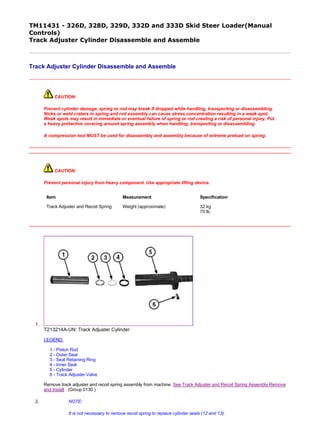
1.
T213214A-UN: Track Adjuster Cylinder
LEGEND:
1 - Piston Rod
2 - Outer Seal
3 - Seal Retaining Ring
4 - Inner Seal
5 - Cylinder
6 - Track Adjuster Valve
Remove track adjuster and recoil spring assembly from machine. See Track Adjuster and Recoil Spring Assembly Remove
and Install . (Group 0130.)
2. NOTE:
It is not necessary to remove recoil spring to replace cylinder seals (12 and 13).
Item Measurement Specification
Track Adjuster and Recoil Spring Weight (approximate) 32 kg
70 lb.
1/3
2019/11/27file:///C:/ProgramData/Service%20ADVISOR/Temp/TM11431_09001faa813...
2. Remove recoil spring (8), if necessary. See Track Adjuster Recoil Spring Remove and Install . (Group 0130.)
3. Tighten track adjuster valve (6).
4. Pump cylinder (5) with grease and remove piston rod (1) from cylinder.
5. Clean out excess grease from cylinder to access seals in end of cylinder.
6.
T213208A-UN: Cylinder Seals (S.N. —192141)
LEGEND:
2 - Inner Seal
3 - Seal Retaining Ring
4 - Outer Seal
TX1081382A-UN: Cylinder Seals (S.N. 192142— )
LEGEND:
2 - Inner Seal
3 - Seal Retaining Ring
4 - Outer Seal
Remove outer seal (2) from cylinder.
7. NOTE:
For cylinders on machines (S.N. —192141), remove seal retaining ring (3) from inner seal (4) before
removing seal from cylinder.
Remove seal retaining ring (3) and inner seal (4) from cylinder.
8. Clean and inspect parts for damage. Repair or replace parts as necessary.
9. NOTE:
2/3
2019/11/27file:///C:/ProgramData/Service%20ADVISOR/Temp/TM11431_09001faa813...
3. For cylinders on machines (S.N. —192141), install inner seal in cylinder with retaining ring groove facing
outward. Install seal retaining ring into groove of inner seal.
Install inner seal and seal retaining ring in cylinder.
10. Install outer seal in cylinder.
11. Loosen track adjuster valve.
12. Apply grease to piston rod and install in cylinder.
13. Completely compress piston rod in cylinder.
14. Tighten track adjuster valve.
15. Install recoil spring, if necessary. See Track Adjuster Recoil Spring Remove and Install . (Group 0130.)
16. Install track adjuster and recoil spring assembly to machine. See Track Adjuster and Recoil Spring Assembly Remove and
Install . (Group 0130.)
KK70125,0000772-19-20101022
3/3
2019/11/27file:///C:/ProgramData/Service%20ADVISOR/Temp/TM11431_09001faa813...
4. TM11431 - 326D, 328D, 329D, 332D and 333D Skid Steer Loader(Manual
Controls)
Axle Housing Remove and Install
Axle Housing Remove and Install
1. Remove front attachment and park machine on flat level surface.
2. Raise and block machine. See Raising and Blocking Machine . (Group 1740.)
3. Remove wheel from axle being serviced. See Wheel Remove and Install . (Group 0110.)
4. Drain chain case oil. See Change Chain Case Oil . (Operator's Manual.)
5. Clean area around axle housing to prevent debris from entering chain case.
6.
CAUTION:
Prevent possible crushing injury from heavy component. Use appropriate lifting device.
T198842A-UN: Axle Housing
LEGEND:
1 - Axle Housing
2 - Nut (8 used)
Support axle housing (1) using appropriate lifting device. Remove axle housing.
Item Measurement Specification
Axle Housing Weight (approximate) 33 kg
72 lb.
1/3
2019/11/27file:///C:/ProgramData/Service%20ADVISOR/Temp/TM11431_09001faa810...
5. 7. Clean and inspect parts. Repair or replace parts as necessary. See Axle Housing Disassemble and Assemble .
(Group 0201.)
8.
T198847A-UN: Axle Housing O-Ring
LEGEND:
3 - O-Ring
Install new O-ring (3) in groove on axle housing.
9. Fill axle housing with oil.
Item Measurement Specification
Axle Housing Capacity 237 mL
8 oz.
2/3
2019/11/27file:///C:/ProgramData/Service%20ADVISOR/Temp/TM11431_09001faa810...
6. 10.
T198848A-UN: Chain Sprocket Position
LEGEND:
4 - Chain Sprocket Hub
Position chain sprocket hub (4) to be visible through hole in chain case.
11. Install UP marking in axle housing, facing up.
12. Install axle shaft into chain sprocket hub and slide axle housing over mounting studs. Loosely install nuts.
13. Slide axle housing to tighten drive chain. See Drive Chain Tension Check and Adjustment . (Group 9020-25.)
14. Fill chain case with oil. See Change Chain Case Oil . (Operator's Manual.)
15. Install wheel. See Wheel Remove and Install . (Group 0110.)
16. Remove blocking. See Raising and Blocking Machine . (Group 1740.)
TF44157,0000EA2-19-20100915
3/3
2019/11/27file:///C:/ProgramData/Service%20ADVISOR/Temp/TM11431_09001faa810...
7. TM11431 - 326D, 328D, 329D, 332D and 333D Skid Steer Loader(Manual Controls)
Axle Housing Disassemble and Assemble
Axle Housing Disassemble and Assemble
TX1068755-UN: Axle Housing Assembly
LEGEND:
1 - Snap Ring
2 - Washer
3 - Shim (as required)
4 - Washer
5 - Inner Bearing
6 - Inner Bearing Cup
7 - Axle Housing
8 - Outer Bearing Cup
9 - Outer Bearing
10 - Seal
11 - Axle Shaft
1.
T198859A-UN: Axle Housing
LEGEND:
1 - Snap Ring
Place axle housing in a press. Remove snap ring (1), washer and shims.
1/3
2019/11/27file:///C:/ProgramData/Service%20ADVISOR/Temp/TM11431_09001faa810...
8. 2.
TX1068760A-UN: Axle Shaft
LEGEND:
5 - Inner Bearing
11 - Axle Shaft
Place axle housing in a press with support under housing flange. Press axle shaft (11) down until axle shaft drops free of inner bearing (5).
3. Remove inner bearing and cup.
4. Remove seal.
5. IMPORTANT:
Outer axle bearing will be destroyed when removed. Remove bearing only if replacement is necessary. Replace bearing and cup as a set.
Remove outer axle bearing and cup only if necessary. Do not reuse bearing and cup.
6. Inspect axle shaft for wear or damage. Repair or replace as necessary.
7. If removed, install new outer bearing with taper facing up. Press bearing onto shoulder of axle shaft.
8. If removed, install outer bearing cup.
9. Install seal.
10. Install axle housing over axle shaft.
11. Install inner bearing over axle shaft.
12. NOTE:
Rotate axle housing while installing bearing.
Press bearing onto axle housing until resistance is felt.
13. Install washer and snap ring. Push snap ring to top of groove. Do not install shims at this time.
14.
T198863A-UN: Rolling Drag Torque
Install a temporary cap screw and nut in one hole of the mounting flange and tighten.
2/3
2019/11/27file:///C:/ProgramData/Service%20ADVISOR/Temp/TM11431_09001faa810...
9. 15. Place torque wrench on temporary cap screw at a right angle to the centerline. Check rolling drag torque. Apply pressure until rolling drag torque is reached.
16.
T198864A-UN: Bearing Pre-Load Measurement
While maintaining pressure, measure distance between washer and snap ring. Add 0.025 mm (0.001 in.) to the measured value to determine the number of shims required for bearing
pre-load.
17. Remove snap ring and washer. Install required shims and washer.
18. Install snap ring.
19. Apply force to axle shaft to seat bearing and shims against snap ring.
20. Check rolling drag torque. Repeat procedure until specification is reached.
Item Measurement Specification
Axle Bearing Rolling Drag Torque 4.52—13.56 N·m
40—120 lb-in.
Item Measurement Specification
Axle Shaft Force 44 482 N
10 000 lb-force
Item Measurement Specification
Axle Bearing Rolling Drag Torque 4.52—13.56 N˙m
40—120 lb-in.
TF44157,0000EA3-19-20091217
3/3
2019/11/27file:///C:/ProgramData/Service%20ADVISOR/Temp/TM11431_09001faa810...
10. TM11431 - 326D, 328D, 329D, 332D and 333D Skid Steer Loader(Manual
Controls)
Chain Case Access Plate Remove and Install
Chain Case Access Plate Remove and Install
1. Remove front attachment and park machine on flat level surface.
2. Drain chain case oil. See Change Chain Case Oil . (Operator's Manual.)
3.
T198871A-UN: Chain Case Access Plate
LEGEND:
1 - Nut (12 used)
2 - Access Plate
Remove access plate (2).
4. Clean and inspect parts.
5. Install access plate with gasket.
6. Fill chain case with oil. See Change Chain Case Oil . (Operator's Manual.)
Item Measurement Specification
Chain Case Access Plate Nut Torque 45 N˙m
33 lb-ft
TF44157,0000EA4-19-20100204
1/1
2019/11/27file:///C:/ProgramData/Service%20ADVISOR/Temp/TM11431_09001faa810...
11. TM11431 - 326D, 328D, 329D, 332D and 333D Skid Steer Loader(Manual
Controls)
Drive Chain and Sprocket Remove and Install
Drive Chain and Sprocket Remove and Install
1. Remove front attachment and park machine on flat level surface.
2. Raise and block machine. See Raising and Blocking Machine . (Group 1740.)
3. Drain chain case oil. See Change Chain Case Oil . (Operator's Manual.)
4. Remove chain case access plate. See Chain Case Access Plate Remove and Install . (Group 0250.)
5. Remove axle housing for each drive chain being serviced. See Axle Housing Remove and Install . (Group 0201.)
6. NOTE:
Remove rear axle housing and rear drive chain from drive sprocket before removing front drive
chain.
T198879A-UN: Chain Case
LEGEND:
1 - Drive Sprocket
2 - Front Drive Chain
3 - Rear Drive Chain
Slide rear axle sprocket forward. Remove rear drive chain (3) from drive sprocket (1) and rear axle sprocket.
7. NOTE:
To remove rear axle sprocket, lift sprocket to top of chain case and pull bottom of sprocket out
over lip of chain case.
Remove rear axle sprocket.
8. Slide front axle sprocket rearward. Remove front drive chain (2) from drive sprocket and front axle sprocket.
9. NOTE:
If removal of front axle sprocket is necessary, hydrostatic motor must be removed. See
1/2
2019/11/27file:///C:/ProgramData/Service%20ADVISOR/Temp/TM11431_09001faa810...
12. Thank you very much for
your reading. Please Click
Here. Then Get COMPLETE
MANUAL. NO WAITING
NOTE:
If there is no response to
click on the link above,
please download the PDF
document first and then
click on it.
13. Hydrostatic Motor and Park Brake Remove and Install . (Group 0360.)
Remove front axle sprocket.
10. Clean and inspect parts. Repair or replace parts as necessary.
11. If removed, install front axle sprocket.
12. Install front drive chain.
13. Install rear axle sprocket and rear drive chain.
14. Install axle housing. See Axle Housing Remove and Install . (Group 0201.)
15. Install chain case access plate. See Chain Case Access Plate Remove and Install . (Group 0250.)
16. Fill chain case with oil. See Change Chain Case Oil . (Operator's Manual.)
17. Lower machine to ground.
TF44157,0000EA5-19-20091218
2/2
2019/11/27file:///C:/ProgramData/Service%20ADVISOR/Temp/TM11431_09001faa810...
14. TM11431 - 326D, 328D, 329D, 332D and 333D Skid Steer Loader(Manual
Controls)
Steering Dampener Remove and Install
Steering Dampener Remove and Install
1. Remove front attachment and park machine on flat level surface.
2. Raise operator's station. See Raising Operator's Station . (Group 1810.)
3.
T199894A-UN: Steering Dampener
LEGEND:
1 - Mounting Hardware
2 - Steering Dampener
3 - Cross Shaft Bell Crank
4 - Cap Screw
Remove mounting hardware (1) from top of steering dampener (2).
4. Remove cap screw (4) from bottom of steering dampener. Lift steering dampener out of machine.
5. Inspect steering dampener. See Steering Dampener Inspection . (Group 0315.)
6. Lower steering dampener into machine. Install cap screw (4) in bottom of steering dampener.
7. Install mounting hardware to top of steering dampener.
8. Make sure the steering lever contacts the stop screws in both forward and reverse positions before dampener reaches its
travel limit. Install or remove shim washer(s) on rod end as required.
9. Tighten dampener mounting cap screws to specification.
10. Lower operator's station. See Raising Operator's Station . (Group 1810.)
Item Measurement Specification
Dampener Mounting Hardware Torque 40 N·m
30 lb-ft
TF44157,0000EC2-19-20100205
1/1
2019/11/27file:///C:/ProgramData/Service%20ADVISOR/Temp/TM11431_09001faa810...
15. TM11431 - 326D, 328D, 329D, 332D and 333D Skid Steer Loader
(Manual Controls)
Steering Dampener Inspection
Steering Dampener Inspection
1. Move steering dampener rod through its full range of motion. Steering dampener should operate smoothly with
some resistance to movement. If no resistance is noted, or if steering dampener is leaking, replace steering
dampener.
2. Test steering dampener as follows:
With steering dampener fully extended, apply 9 kg (20 lb) of force to rod end. It must take 1—5 seconds for
dampener to fully retract.
With steering dampener fully retracted, apply 9 kg (20 lb) of pull to rod end. It must take 1—5 seconds for
dampener to fully extend.
3. Replace steering dampener if test results are not within specification.
TF44157,0000E96-19-20091218
1/1
2019/11/27file:///C:/ProgramData/Service%20ADVISOR/Temp/TM11431_09001faa810...