This document summarizes the design and testing of a fuel cell powered unmanned aerial vehicle (UAV) for low altitude surveillance missions. The UAV was designed with an aerodynamic glider configuration and powered by a 200 W polymer electrolyte membrane fuel cell system fed by a chemical hydride hydrogen generator, along with lithium polymer batteries. Bench and flight tests showed the hybrid power system enabled flight durations of nearly 4 hours. The document discusses the aircraft design process, onboard power system, results from testing, and lessons learned for optimizing long endurance fuel cell powered UAVs.
![A fuel cell powered unmanned aerial vehicle for
low altitude surveillance missions
N. Lape~
na-Rey a,*
, J.A. Blanco a
, E. Ferreyra a
, J.L. Lemus a
, S. Pereira,
E. Serrot a
a
Boeing Research & Technology Europe, S.L.U, Spain
a r t i c l e i n f o
Article history:
Received 31 August 2016
Received in revised form
20 January 2017
Accepted 24 January 2017
Available online xxx
Keywords:
Unmanned aerial vehicle
Polymeric electrolyte membrane
fuel cell
Hydrogen
Hybrid power management
Sodium borohydride
Long endurance
a b s t r a c t
Boeing Research & Technology Europe has designed, developed and subsequently bench
and flight tested, in a wide range of different operative conditions, an electric Unmanned
Air Vehicle (UAV) powered by a hybrid energy source. The energy source features a 200 We
Polymer Electrolyte Membrane (PEM) fuel cell system fed by a chemical hydride hydrogen
generator that produces highly pure hydrogen at the fuel cell operating pressure from the
controlled hydrolysis of Sodium Borohydride (NaBH4), resulting in 900 Wh of energy from
1 L of chemical solution. Equipped also with high specific energy Lithium Polymer batteries,
this fuel cell powered UAV is able to achieve flight durations close to 4 h.
This paper summarizes the aircraft and systems design, the results of the bench and
flight tests along with the main challenges faced during this development and the lessons
learned for future optimization.
© 2017 Hydrogen Energy Publications LLC. Published by Elsevier Ltd. All rights reserved.
Introduction
Electric propulsion for mini-UAVs (Unmanned Air Vehicles
with Maximum Take of Weight, MTOW, below 25 kg) provides
a route for lower capital cost, reduced carbon footprint and
quieter Unmanned Aerial System (UAS) operations. However,
state-of-the-art advanced lithium polymer battery technology
offers limited specific energy, which provides a typical mini-
UAV with an endurance of 60e90 min and, therefore, limits
the flight mission or increases operational costs [1,2].
Combining batteries and fuel cells in hybrid propulsion
systems can significantly increase the UAV's endurance,
opening new mission capabilities not previously possible for
electric mini-UAVs [3e5]. Indeed, UAVs with MTOW below
25 kg are a niche application in which air cooled PEM fuel cells,
in their current maturity stage, already meet the weight tar-
gets while offering unique competitive advantages over con-
ventional power sources including: low noise and vibration so
the airplane can fly at lower altitudes without being discov-
ered and use simpler cameras, environmental benefits (no
greenhouse gases, GHG, emissions) and low thermal signa-
ture. Moreover, electric motors are more efficient and have far
better reliability than their non-electric counterparts.
* Corresponding author.
E-mail address: nieves.lapena@boeing.com (N. Lape~
na-Rey).
Available online at www.sciencedirect.com
ScienceDirect
journal homepage: www.elsevier.com/locate/he
i n t e r n a t i o n a l j o u r n a l o f h y d r o g e n e n e r g y x x x ( 2 0 1 7 ) 1 e1 5
http://dx.doi.org/10.1016/j.ijhydene.2017.01.137
0360-3199/© 2017 Hydrogen Energy Publications LLC. Published by Elsevier Ltd. All rights reserved.
Please cite this article in press as: Lape~
na-Rey N, et al., A fuel cell powered unmanned aerial vehicle for low altitude surveillance
missions, International Journal of Hydrogen Energy (2017), http://dx.doi.org/10.1016/j.ijhydene.2017.01.137](https://image.slidesharecdn.com/j-230206105836-a236b105/85/j-ijhydene-2017-01-137-pdf-1-320.jpg)
![A fuel cell powered unmanned aerial vehicle for
low altitude surveillance missions
N. Lape~
na-Rey a,*
, J.A. Blanco a
, E. Ferreyra a
, J.L. Lemus a
, S. Pereira,
E. Serrot a
a
Boeing Research & Technology Europe, S.L.U, Spain
a r t i c l e i n f o
Article history:
Received 31 August 2016
Received in revised form
20 January 2017
Accepted 24 January 2017
Available online xxx
Keywords:
Unmanned aerial vehicle
Polymeric electrolyte membrane
fuel cell
Hydrogen
Hybrid power management
Sodium borohydride
Long endurance
a b s t r a c t
Boeing Research & Technology Europe has designed, developed and subsequently bench
and flight tested, in a wide range of different operative conditions, an electric Unmanned
Air Vehicle (UAV) powered by a hybrid energy source. The energy source features a 200 We
Polymer Electrolyte Membrane (PEM) fuel cell system fed by a chemical hydride hydrogen
generator that produces highly pure hydrogen at the fuel cell operating pressure from the
controlled hydrolysis of Sodium Borohydride (NaBH4), resulting in 900 Wh of energy from
1 L of chemical solution. Equipped also with high specific energy Lithium Polymer batteries,
this fuel cell powered UAV is able to achieve flight durations close to 4 h.
This paper summarizes the aircraft and systems design, the results of the bench and
flight tests along with the main challenges faced during this development and the lessons
learned for future optimization.
© 2017 Hydrogen Energy Publications LLC. Published by Elsevier Ltd. All rights reserved.
Introduction
Electric propulsion for mini-UAVs (Unmanned Air Vehicles
with Maximum Take of Weight, MTOW, below 25 kg) provides
a route for lower capital cost, reduced carbon footprint and
quieter Unmanned Aerial System (UAS) operations. However,
state-of-the-art advanced lithium polymer battery technology
offers limited specific energy, which provides a typical mini-
UAV with an endurance of 60e90 min and, therefore, limits
the flight mission or increases operational costs [1,2].
Combining batteries and fuel cells in hybrid propulsion
systems can significantly increase the UAV's endurance,
opening new mission capabilities not previously possible for
electric mini-UAVs [3e5]. Indeed, UAVs with MTOW below
25 kg are a niche application in which air cooled PEM fuel cells,
in their current maturity stage, already meet the weight tar-
gets while offering unique competitive advantages over con-
ventional power sources including: low noise and vibration so
the airplane can fly at lower altitudes without being discov-
ered and use simpler cameras, environmental benefits (no
greenhouse gases, GHG, emissions) and low thermal signa-
ture. Moreover, electric motors are more efficient and have far
better reliability than their non-electric counterparts.
* Corresponding author.
E-mail address: nieves.lapena@boeing.com (N. Lape~
na-Rey).
Available online at www.sciencedirect.com
ScienceDirect
journal homepage: www.elsevier.com/locate/he
i n t e r n a t i o n a l j o u r n a l o f h y d r o g e n e n e r g y x x x ( 2 0 1 7 ) 1 e1 5
http://dx.doi.org/10.1016/j.ijhydene.2017.01.137
0360-3199/© 2017 Hydrogen Energy Publications LLC. Published by Elsevier Ltd. All rights reserved.
Please cite this article in press as: Lape~
na-Rey N, et al., A fuel cell powered unmanned aerial vehicle for low altitude surveillance
missions, International Journal of Hydrogen Energy (2017), http://dx.doi.org/10.1016/j.ijhydene.2017.01.137](https://image.slidesharecdn.com/j-230206105836-a236b105/75/j-ijhydene-2017-01-137-pdf-1-2048.jpg)
![During the last decade the UAS industry has grown sub-
stantially, mainly through the development and maturation of
military applications, followed by a wide range of civil appli-
cations, such as: border control, coastguard, law enforcement
and police support, power line, water pipes and gas pipes
monitoring, terrain surveillance, environmental surveillance,
communications, etc. Market and application research seems
to show a growing trend towards mini-UASs mainly due to
lower cost and investment risk, along with less infrastructural
needs for tactical surveillance. The selection of this specific
type of UAVs would facilitate the upcoming certification pro-
cess and a larger number of fuel cell powered UAVs is expected
in the near future. Numerous flight demonstrations of hybrid
FC/battery-powered UAVs have been reported in recent years
from universities, research organizations and commercial
entities across the world for low and high altitude surveillance
[6e21]. Some of the prototypes that have successfully
demonstrated the feasibility of this application include: the
Global Observer [6], a high altitude long endurance (HALE) UAV
developed by AeroVironment (USA 2005); the mini-UAV
developed by Georgia Technical University [7] (USA, 2006);
the Spider-Lion [8], a micro-UAV developed by The Naval
Research Laboratory (USA, 2006); the Hyfish [9], a mini-UAV
developed by DLR & Horizon Energy Systems (Germany,
2007); the SAE Pterosoar [10] (California State University,
Oklahoma State University, Horizon Energy Systems, USA,
Nov 2007), the Puma [11] (AeroVironment & Adaptive Materials
Inc e SOFC, June 2007), the Endurance (Solar Bubbles &
Adaptive Materials, Inc., October 2008) [12], the Boomerang®
[13] (BlueBird Aero Systems & Horizon Energy Systems), which
was presented at the “Unmanned Systems 2009” conference,
and the WanderB®
[14] (BlueBird Aero Systems & Horizon En-
ergy Systems), capable of 10h endurance flights. The longest
endurance unofficial record is held by the Ion Tiger of The
Naval Research Laboratory (NRL's), Protonex Technology Cor-
poration, the University of Hawaii, and HyperComp Engi-
neering, which flew 48 h and 1 min in 2013 [15,16]. Other recent
demonstrations include: the first fuel cell powered unmanned
aerial vehicle (UAV) flights in India carried out by the Canadian
fuel cell specialist EnergyOr Technologies Inc. in collaboration
with Radiant Coral Digital Technologies (RCDT), an Indian
technology and engineering company that provides products
and services to the aerospace and defense sectors [17]; the
research done at Loughborough University UK (Skywalker X8)
using ArduPilot's autonomous take-off [18]; the automatically
controlled Thunderbird” (LN60F) UAV sponsored by the China
Aviation Industry Group and independently developed by
Liaoning General Aviation Academy [19] (the aircraft wingspan
width is 10.5 m, weights 257 kg with a cruise speed of 120 km/h
and the endurance was 4 h) or the UAV of KIMS (The Korean
Institute of Materials Research) [20]; finally, an electric proto-
type of one of the commercially available UAVs with longer
proven operation in real flight missions, the InSitu ScanEagle,
also successfully completed its first hydrogen-powered fuel
cell flight (two-and-a-half-hour flight test) making an impor-
tant step in the move toward hydrogen-powered fuel cell so-
lutions as an alternative to expensive gas and heavy fuel
solutions in UAVs [21]. The Naval Research Laboratory (NRL)
and United Technologies (UTC) took UTC's 1500 W (2 HP) fuel
cell and integrated it with NRL's hydrogen fueling solution into
a ScanEagle propulsion module. It is worth mentioning that
most of these developments are not well documented and,
thus, the characteristics, the performance, the reliability, the
practicality or the technology readiness level of the electric
propulsion systems used are not well known. In most cases,
the hydrogen generation or storage method is not even
mentioned. Finally, the capabilities of the UAVs (ceiling, power
consumption, flight speed, payload capability, etc.) are not
well known either.
To date, PEM fuel cells relying on hydrogen as fuel have
been most commonly used in mini-UAVs, mainly due to their
lower operating temperature (thus, low thermal signature)
and relative compactness compared to other types of fuel
cells. The majority of PEM fuel cell/Li ion batteries-powered
systems tested to date rely on compressed gas cylinders
which are delivered to the UAV user's location (and used to
refill the UAV hydrogen tanks on-site with a compressor) or
chemical hydride systems to produce hydrogen on-board.
The former option presents challenges related to safety,
fuel availability on site, limited UAV on-board storage capa-
bility (thus, compromising the UAV endurance), excessive
fuel costs (due to fuel transport to remote locations) and
unknown carbon footprint. On the other hand, most of the
chemical hydride systems developed so far still pose chal-
lenges related to low ambient temperature operation, by-
product disposal and, thus, UAV's weight loss (i.e., center of
gravity shift) during flight; also reliability and ability to scale
up (and therefore maximize the UAV flight endurance) are
yet to be demonstrated. Finally, the high maintenance
currently required needs to be decreased to make the tech-
nology more user friendly. However, once matured, this
technology would offer an excellent option for operation in
remote areas.
Aircraft and onboard systems design
Aircraft design
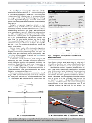
The ideal airframe configuration is that with very high aero-
dynamic efficiency and enough internal volume to accom-
modate the fuel cell system and the fuel system. It is worth
mentioning that, contrary to the fuel cells in this particular
power range, hydrogen based fuel systems are not yet opti-
mized in terms of weight and volume for most aeronautical
applications.
Fig. 1 e Aircraft design.
i n t e r n a t i o n a l j o u r n a l o f h y d r o g e n e n e r g y x x x ( 2 0 1 7 ) 1 e1 5
2
Please cite this article in press as: Lape~
na-Rey N, et al., A fuel cell powered unmanned aerial vehicle for low altitude surveillance
missions, International Journal of Hydrogen Energy (2017), http://dx.doi.org/10.1016/j.ijhydene.2017.01.137](https://image.slidesharecdn.com/j-230206105836-a236b105/85/j-ijhydene-2017-01-137-pdf-2-320.jpg)
![fuel cell), the propulsion system (the electronic speed
controller or ESC and the electric motor) and a telemetry
system (to download data from the fuel cell system and other
sensors).
The fuel Cell/LiPo hybrid power source included a
commercially available fuel cell system from Horizon Energy
Systems, commercially available Lithium Polymer batteries
and a hybrid power management card designed also by Ho-
rizon Energy Systems. This system was chosen because it is
one of the most lightweight and compact commercially
available systems for this power range. A small fraction of a
typical UAV mission, mainly takeoff and climb stages, de-
mand an amount of power meaningfully higher than that for
the rest of the flight. To optimize the weight of the overall
system, the fuel cell was sized mainly for cruise flight whereas
the batteries provided the additional power required for
takeoff and climb as well as the power for transitory high-
powered maneuvers. The hybrid power management board
performs two tasks:
1. Merges the Lithium Polymer battery (5000 mh 6S 20C)
power and the fuel cell power directly into the propulsion
system, thanks to a high power Schottky diode.
2. Charges the lithium-polymer battery whenever there is a
surplus of energy generating capacity at the fuel cell and
the battery voltage is below a certain threshold.
The commercially available 200 We output rate fuel cell
system (Fig. 12 and Ref. [27]) had a rated capacity of 900 Wh
using 1 L of a solution of 20% wt. NaBH4 in water, and a fueled
weight close to 2.5 kg, including Thunderpower Lith-
iumePolymer batteries and the fuel generating cartridge. The
fuel cell stack produces electricity, water and heat from the
electrochemical reaction of the highly pure hydrogen,
generated from the controlled hydrolysis of NaBH4, and oxy-
gen from the air. Section 3 provides further details of the fuel
cell system.
The propulsion block consisted of the ESC and the electric
motor. The cruise speed was calculated for a 18.5 1200
pro-
peller turning at around 3200 rpm in-runner brushless motors
that provide such low speeds are very difficult to find, so a
combination with gearbox was necessary. The option selected
was the lightest, comprising a Hacker B50 19S electric brush-
less motor and a 6.7:1 gearbox integrated with the motor
(weighting 198 g in total). After the first battery flight tests in
which several propellers were tested, the initial calculations
proved to be optimum.
The electronic speed controller chosen was the Castle
Creations Phoenix ICE Lite 50, capable of withstanding a cur-
rent of 50 A, that is, 1200 W at 24 V weighing only 48 g. Its
Table 2 e Chosen energy storage systems.
Source Weight (kg) Maximum power (W) Energy (Wh) Power density (W/kg) Energy density (Wh/kg)
Fuel cell system 2 200 900 100 450
LiPo battery 0.8 2200 110 2750 138
Control LiPo battery 0.4 222 74 555 185
Fig. 11 e Propulsion block diagram.
Fig. 12 e Fuel cell system (200 We fuel cell
system þ 900 Wh H2 generator from NaBH4).
i n t e r n a t i o n a l j o u r n a l o f h y d r o g e n e n e r g y x x x ( 2 0 1 7 ) 1 e1 5
6
Please cite this article in press as: Lape~
na-Rey N, et al., A fuel cell powered unmanned aerial vehicle for low altitude surveillance
missions, International Journal of Hydrogen Energy (2017), http://dx.doi.org/10.1016/j.ijhydene.2017.01.137](https://image.slidesharecdn.com/j-230206105836-a236b105/85/j-ijhydene-2017-01-137-pdf-6-320.jpg)
![weight is important since its position is far from the center of
gravity of the plane. The speed signal that comes from the
control block (see Section 2.2.1) was connected to this device
through an optocoupler to keep the blocks electrically
isolated.
The chosen telemetry system was a commercially avail-
able EagleTreeSystems set that allows First Person View (FPV)
with an On Screen Display (OSD) which indicates GPS data,
airspeed, heading, barometric altitude, propeller rpms and
outside air temperature and motor temperature and electric
indications, such as power and battery voltage. All the
telemetry data was both recorded in an on-board logger and
also sent to ground were a dedicated computer displayed and
recorded the values for later analysis and redundancy. These
indicators are essential for the pilot to control the plane and
also for the rest of the flight tests crew to calibrate the auto-
pilot's parameters and monitor the flight progress. The video
transmitter was placed on a custom made heat sink that was
placed where the normal flight air-flow could cool the whole
system. Its transmission band was centered in 1.2 GHz.
The fuel cell stack electronics provided an RS-232 serial
output that was sent to the ground control station via an
audiomodem designed and developed by BRTE for that
purpose. The audio generated at this audiomodem was sent
via the video transmitter audio channel.
Fuel cell system
Fuel cell stack
The application of the PEM fuel cells as a primary power
source in electric vehicles has received increasing attention in
the last few decades, mainly in the car industry. PEM fuel cells
use a dense and gas tight polymer membrane electrolyte,
which conducts hydrogen ions in a certain range of temper-
ature and humidity. On the contrary, both the anode and the
cathode are porous. The advantages of PEM fuel cells are that
the production of the cell is simple, they are able to withstand
large pressure differentials, material corrosion problems are
minimal, and they have demonstrated long life in several
stationary and transport applications.
In this type of fuel cell, hydrogen from the fuel gas stream
is consumed at the anode, yielding electrons that go through
an external circuit and hydrogen ions which go through the
electrolyte towards the cathode [22,23]. There, the protons
combine with the oxygen from the air and the electrons to
produce water.
Anode: 2H2 / 4Hþ
þ 4e
Cathode: O2 þ 4Hþ
þ 4e
/ 2H2O
Thus, the only product of the reaction is water, which does
not dissolve in the electrolyte and is, instead, expelled from
the cathode into the oxidant gas stream. As the PEMFC oper-
ates in the 60e70
C temperature range, this water is pushed
out of the fuel cell by the excess oxidant flow.
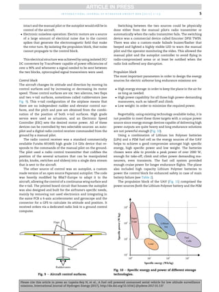
An open cathode stack was chosen (Fig. 13) mainly because
it was commercially available, thus, helping to reduce the cost
of the project, and also because, in general, it is suitable for
low altitude flight surveillance missions (below 1000 m). The
stack can deliver up to 10 A in a voltage range from 32 V (0.91 V
per cell in open circuit) to 21 V (0.6 V per cell at maximum
load). The applicable altitude and temperature range for the
stack is shown in Fig. 14, where the red inner envelope (in the
web version) represents the operating conditions for the fuel
cell rated performance, while the yellow outer envelope (in
the web version) represents the operating conditions for
limited fuel cell performance. Operating altitude affects per-
formance since there is less oxidant for the electrochemical
reactor, leading to lower single cells voltage. A slight drop in
performance (power output) is expected typically at
1000 m ASL. One other factor affecting performance is the
ambient temperature. Higher temperature leads to drying the
PEM membrane inside the stack, reducing its conductivity
and, consequently, the power output of the fuel cell stack. Low
temperatures are counteracted using two methods. The first
Fig. 13 e 200 We fuel cell.
Fig. 14 e Applicable altitude (ASL) and temperature range
for the 200 We open cathode stack [28].
i n t e r n a t i o n a l j o u r n a l o f h y d r o g e n e n e r g y x x x ( 2 0 1 7 ) 1 e1 5 7
Please cite this article in press as: Lape~
na-Rey N, et al., A fuel cell powered unmanned aerial vehicle for low altitude surveillance
missions, International Journal of Hydrogen Energy (2017), http://dx.doi.org/10.1016/j.ijhydene.2017.01.137](https://image.slidesharecdn.com/j-230206105836-a236b105/85/j-ijhydene-2017-01-137-pdf-7-320.jpg)
![one consists on reducing the throttle of the fans at the back of
the stack, effectively reducing the cold air pulling heat from
the cells. The second one consists on increasing the duration
of the conditioning short-circuits [25,26] of the stack, resulting
in the stack self-heating.
Hydrogen generator
The 900 Wh hydrogen generator from Horizon Energy Systems
produces hydrogen on demand, i.e., it produces the amount of
hydrogen that the fuel cell demands, which obviously de-
pends on the fuel cell power output.
The gaseous hydrogen for the fuel cell is obtained at the
right purity (99.99%) and at fuel cell operating pressure
(0.5e0.7 barg) from 1 L of a 20% wt. sodium borohydride
(NaBH4) solution in water via a catalyzed hydrolysis reaction:
NaBH4 þ 2H2O / 4H2 þ NaBO2
The reaction takes place inside a reactor packed with the
catalyst when reaching 70
C. An intake pump feeds the fuel
from the fuel tanks into the reactor. Both the generated
gaseous hydrogen and the byproduct (sodium metaborate
NaBO2) are cooled down through a cooling coil before flowing
into a separator where light highly pure gaseous hydrogen
stays on top and the heavier byproduct stays at the bottom.
The hydrogen is then extracted through a filter/desiccator and
a pressure regulator that reduces the pressure from the 5 barg
in the reactor to the fuel cell operating pressure (0.5 barg)
before feeding the stack. The unreacted NaBH4 is forced again
towards the reactor to try to extract more hydrogen. The
byproduct is recirculated from the separator towards the
reactor where it exhausts the system through a purging valve
towards a tube which is ducted out of the aircraft. The
movement of the byproduct through the pipes in the system
poses the first challenge, operation at low ambient tempera-
tures, since the salt might precipitate in the tubes blocking the
system [24]. The purging procedure is controlled by the
hydrogen generator controller board that also informs the
stack of the relevant parameters such as the reactor's pres-
sure, and sends other data through the stack board to the user
(reactor's temperatures, sensor levels, etc.).
Exhausting the byproduct off the aircraft during flight al-
lows reducing weight progressively over the course of a flight.
Although this could theoretically be an advantage it poses the
second challenge, since the weight-shift and lose would
disrupt the aircraft center of gravity during the flight, which
might negatively affect the aircraft stability if the center of
gravity is shifted out of the its acceptable limits. This is thor-
oughly discussed in section 7.
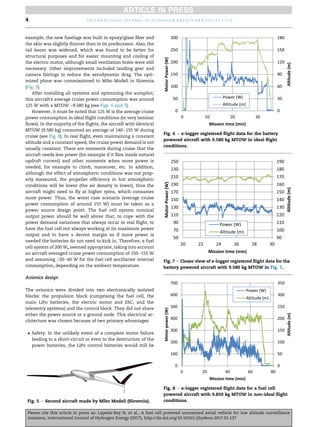
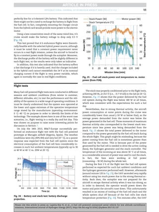
Fig. 15 shows the fuel consumption rate at different power
outputs and ambient temperatures provided by the manu-
facturer. At ~200 W (which would constitute the worse-case
scenario for the UAV cruise power consumption, even in the
worst ambient temperature conditions (40
C)) the fuel con-
sumption was always less than 250 g/h. Therefore, 1 kg of fuel
could lead up to minimum 4 h flights and up to 5 h flights at a
200 W continuous power draw. In practice, the power draw
will vary during flight, even during cruise.
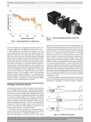
Stack and hydrogen generator bench endurance
test
Prior to mounting the system onboard, the fuel cell was
thoroughly conditioned for several days with compressed
hydrogen gas until the power output was 200 We at 24.5 V (i.e.,
~0.7 V/cell). Once fully conditioned, the fuel cell was tested
with the hydrogen generator on the bench connected to an
electronic programmable load, which simulated the electric
motor, to prove the 900 Wh of energy stated by the manu-
facturer. 1 L of freshly made fuel mixture (20% wt. NaBH4 with
demineralized water) was poured into the fuel tank. After-
wards, the separator was usually primed with 15 ml of dem-
ineralized water. The system was then started and ran for
4.5e5 h at 160 W set in the electronic load.
The results of a typical test are summarized in Figs. 16e18,
which show smooth and successful performance. Fig. 16
shows the total energy (Wh) delivered vs. time during the
test. The straight ascending line looks as expected. Fig. 17
shows how every 20 min the system produced ~50 Wh and
this remained fairly constant with time, and how the Wh
delivered are proportional to the fuel mass consumption, both
Fig. 15 e Fuel consumption of the hydrogen generator [23].
Fig. 16 e Total energy (Wh) vs. time e 1st run.
i n t e r n a t i o n a l j o u r n a l o f h y d r o g e n e n e r g y x x x ( 2 0 1 7 ) 1 e1 5
8
Please cite this article in press as: Lape~
na-Rey N, et al., A fuel cell powered unmanned aerial vehicle for low altitude surveillance
missions, International Journal of Hydrogen Energy (2017), http://dx.doi.org/10.1016/j.ijhydene.2017.01.137](https://image.slidesharecdn.com/j-230206105836-a236b105/85/j-ijhydene-2017-01-137-pdf-8-320.jpg)
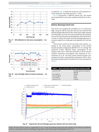
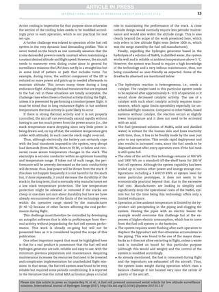
![An oscilloscope logged Vbattery, Ibattery, Vload and Iload
(Fig. 20).
Fig. 21 shows the initial stages of the simulated flight
mission, and for each one, the discharge curve of the battery.
The take-off stage was the most current demanding, peaking
at 25 A from the battery. During climb simulation, the current
of the battery was mostly below 7 A and the stack was pro-
ducing the remaining 8 A. In this stage, the battery current
discharge was ~100 mV/min (Fig. 22).
After the recovery from climb, in the cruise stage, the
battery discharge stabilized and the slope suggested that the
discharge rate was below 200 mV/h (Fig. 23), which is slow
compared to the one during the climb stage (100 mV/min).
Although most of the power delivered to the load was gener-
ated by the fuel cell stack, the battery still needed to deliver
current:
To power the electronics of the controller board of the
stack.
To power the load while the self-heating short-circuits of
the stack occurred. These short-circuits keep the stack
conditioned [25,26] and happen in its normal operation
every 10 s and correspond to the negative spikes seen
throughout the test.
Drawing a conservative trend line, during 4 h of cruise the
voltage would drop only 0.8 V, i.e., from 24.5 to 23.7 V, which is
Fig. 20 e Stack and battery discharge test setup.
Fig. 21 e Battery and stack test: battery initial discharge.
Fig. 22 e Battery and stack test: climb battery discharge.
Fig. 23 e Battery and stack test: cruise battery discharge.
i n t e r n a t i o n a l j o u r n a l o f h y d r o g e n e n e r g y x x x ( 2 0 1 7 ) 1 e1 5
10
Please cite this article in press as: Lape~
na-Rey N, et al., A fuel cell powered unmanned aerial vehicle for low altitude surveillance
missions, International Journal of Hydrogen Energy (2017), http://dx.doi.org/10.1016/j.ijhydene.2017.01.137](https://image.slidesharecdn.com/j-230206105836-a236b105/85/j-ijhydene-2017-01-137-pdf-10-320.jpg)
![Summarizing, the system works properly if a quality con-
trol is implemented but it is complex and requires rigorous
and tedious maintenance. The hydrogen generator is sold as a
swappable system and the required maintenance is done by
the manufacturer. However, that was not found to be practical
for field operation on the other side of the world. Therefore,
the technology must mature to be successfully implemented
in UAVs that aim to be products rather than prototypes.
However, it is theoretically a practical system in which pure
hydrogen is only produced in demand and at low pressure,
which is an incredible advantage that would greatly make
certification easier than with compressed hydrogen gas, for
example. It is also ideal for operation in remote areas, to avoid
mission disruption due to fuel logistics/high cost.
Other competing technologies include the hydrolysis of
NaBH4 but at higher temperature or using for example a water
based HCl or other acidic solution as an agent. Both of these
approaches are simpler, require considerably lower mainte-
nance and use fuel that does not get out of date. One other
interesting option is exploring new chemistries (such as
MgH2), which does not require a catalyst either, is a simpler
system, requires considerably lower maintenance and might
also resolve some of the practical challenges of the system
studied here. However, the considerably higher reaction
temperature poses a thermal management challenge. Finally,
the hydrolysis of alkaline metals (Na or Li) in inert atmo-
spheres seems also a feasible and very promising technology
to be studied. Within the hydrogen storage methods, both
compressed hydrogen and liquid hydrogen should be explored
although they require considerable fuel logistics and might be
less practical for operation in remote areas.
Conclusion
BRT-Europe has corroborated that fuel cell powered electric
UAV low altitude flight missions using off-the-shelf fuel cell
technology and chemical hydrides as a hydrogen source are
feasible.
The fuel cell system chosen was found to be one of the
most lightweight and compact commercially available sys-
tems for this power range. Despite the required maintenance,
the fuel cell system proved to be very reliable although chal-
lenges were encountered when operating in hot weather
conditions, especially with strong thermal activity. The
chemical hydride technology is very promising and once it
reaches the correct readiness level, it could allow having long
endurance electric UAVs without having to store high pres-
sure gaseous hydrogen or liquid hydrogen onboard, which
would be particularly useful for operating at remote locations
or for portable applications since it would simplify the ground
logistics and workflow. This prototype was designed for op-
timum aerodynamics (glider with an L/D ~20) and the flight
tests were all smooth in terms of maneuvering to maximize
endurance. In addition, as it is only a demonstrator, the
aircraft had no payload. These are ideal conditions, which are
not representative of most UAVs that normally have more
restrictive conditions. The ceiling set for this prototype was
~1000 m AGL whereas surveillance UAVs fly up to ~5000 m or
more. The atmospheric conditions at such altitudes are totally
different with much lower pressures and temperatures, and
thus, the fuel cell system design has to be adapted for such
conditions.
r e f e r e n c e s
[1] Unmanned Systems North America 2012. Protonex
announces commercial fuel cell power system for
unmanned applications at AUVSI's unmanned systems
North America 2012. August 2012.
[2] Verstraete D, Harvey JR, Palmer JL. Hardware-in-the-loop
simulation of fuel cell-based hybrid electrical UAV
propulsion. 28th International Congress of Aeronautical
Sciences. September 2012.
[3] Lape~
na-Rey N, Mosquera J, Bataller E, Orti F, Dudfield C,
Orsillo A. Environmentally friendly power sources for
aerospace applications. J Power Sources 2008;181:353e62.
[4] Reitz TL. AFRL/RZ fuel cell program. Propulsion Directorate,
Air Force Research Laboratory. 2010.
[5] Gertler J. US unmanned aerial systems. Congressional
Research Service, Report 7e5700 prepared for Members and
Committees of US Congress. January 2012.
[6] Global Observer from AeroVironment: http://www.avinc.
com/ADC_Project_Details.asp?Prodid¼35.
[7] Fuel Cell UAV from Georgia Institute of Technology: http://
gtresearchnews.gatech.edu/newsrelease/fuel-cell-aircraft.htm.
[8] SpiderLion from Navy Research Labs and Protonex: http://
www.designation-systems.net/dusrm/app4/spider-lion.
html.
[9] HYFISH from Deutsche Raum und Luftfahrt (DLR), Smartfish
and Horizon Energy Systems: http://www.militaryaero
space.com/articles/print/volume-18/issue-6/news/hydro
gen-fuel-cell-technology-takes-off-powering-hyfish-uav.
html.
[10] SAE Pterosoar from California State University, Oklahoma
State University, Horizon Energy systems: http://www.
worldrecordacademy.com/technology/longest_micro_UAV_
flight_world_record_set_by_Pterosoar_70905.htm.
[11] Puma from AeroVironment: http://www.avinc.com/uas/adc/
fuel_cell_puma/.
[12] Endurance from SolarBubbles: http://gas2.org/2008/11/23/
michigan-students-set-world-record-for-longest-flight-by-
fuel-cell-powered-plane/.
[13] Boomerang from BlueBird Aerosystems and Horizon Energy
Systems: http://www.bluebird-uav.com/Boomerang.html.
[14] http://www.flightglobal.com/news/articles/bluebird-unveils-
10h-endurance-wanderb-394566/.
[15] Ion tiger: http://www.nrl.navy.mil/media/news-releases/
2013/nrl-shatters-endurance-record-for-small-electric-uav.
[16] Rocheleau R, Virji M, Bethune K. Fuel cell stack testing and
durability in support of ion tiger UAV e final technical report.
Hawai Natural Energy Institute; June 2010.
[17] http://www.fuelcelltoday.com/news-events/news-archive/
2013/february/energyor-conducts-first-fuel-cell-uav-flights-
in-india.
[18] http://diydrones.com/profiles/blogs/hydrogen-fuel-cell-uav.
[19] http://www.suasnews.com/2012/08/18346/.
[20] http://www.engadget.com/2007/10/17/korean-researchers-
build-a-fuel-cell-uav-that-runs-for-10-hours/.
[21] http://www.insitu.com/press/hydrogen-powered-fuel-cell-
flies-scaneagle.
[22] Kordesch K, Simander J. Fuel cells and their applications.
VCH; 1996.
[23] Larminie J, Dicks A. Fuel cell systems explained. Wiley; 1999.
[24] Okumus E, San FGB, Okur O, Turk BE, Cengelci E, Kilic M,
et al. Development of boron-based hydrogen and fuel cell
i n t e r n a t i o n a l j o u r n a l o f h y d r o g e n e n e r g y x x x ( 2 0 1 7 ) 1 e1 5
14
Please cite this article in press as: Lape~
na-Rey N, et al., A fuel cell powered unmanned aerial vehicle for low altitude surveillance
missions, International Journal of Hydrogen Energy (2017), http://dx.doi.org/10.1016/j.ijhydene.2017.01.137](https://image.slidesharecdn.com/j-230206105836-a236b105/85/j-ijhydene-2017-01-137-pdf-14-320.jpg)
![system for small unmanned aerial vehicle. Int J Hydrogen
Energy 2016. http://dx.doi.org/10.1016/j.ijhydene.2016.09.009.
September Edition.
[25] Gupta G, Wu B, Mylius S, Offer G. A systematic study on the
use of short circuiting for the improvement of proton
exchange membrane fuel cell performance. Int J Hydrogen
Energy 2016. http://dx.doi.org/10.1016/j.ijhydene.2016.10.080.
November Edition.
[26] Kim J, Kim D, Kim S, Nam S, Kim T. Humidification of
polymer electrolyte membrane fuel cell using short circuit
control for unmanned aerial vehicle applications. Int J
Hydrogen Energy 15 May 2014;39(15):7925e30.
[27] Horizon Energy Systems, HES: http://www.hes.sg.
[28] Aeropak technical datasheet (http://resources.arcolaenergy.
com/docs/TechnicalDataSheets/).
i n t e r n a t i o n a l j o u r n a l o f h y d r o g e n e n e r g y x x x ( 2 0 1 7 ) 1 e1 5 15
Please cite this article in press as: Lape~
na-Rey N, et al., A fuel cell powered unmanned aerial vehicle for low altitude surveillance
missions, International Journal of Hydrogen Energy (2017), http://dx.doi.org/10.1016/j.ijhydene.2017.01.137](https://image.slidesharecdn.com/j-230206105836-a236b105/85/j-ijhydene-2017-01-137-pdf-15-320.jpg)


