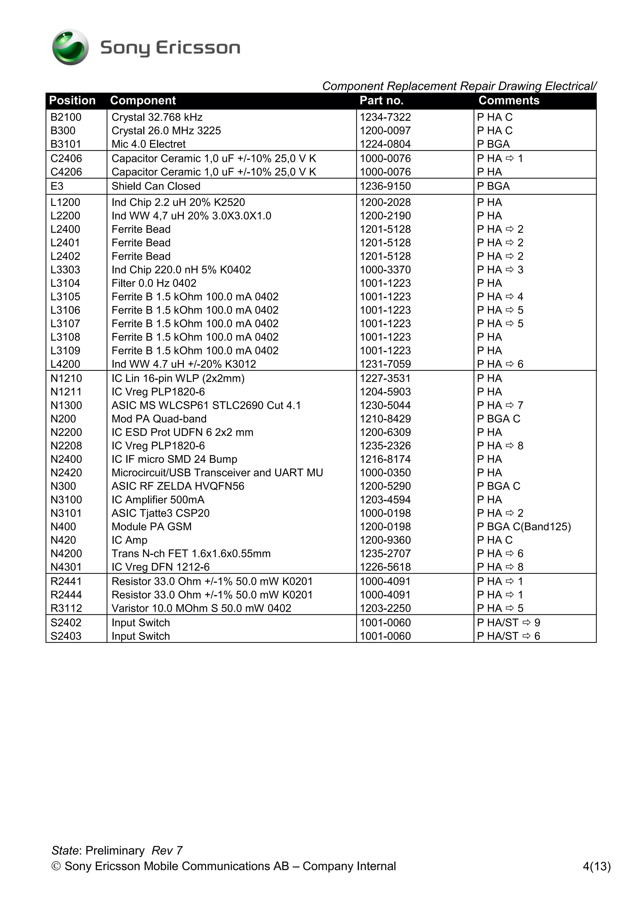
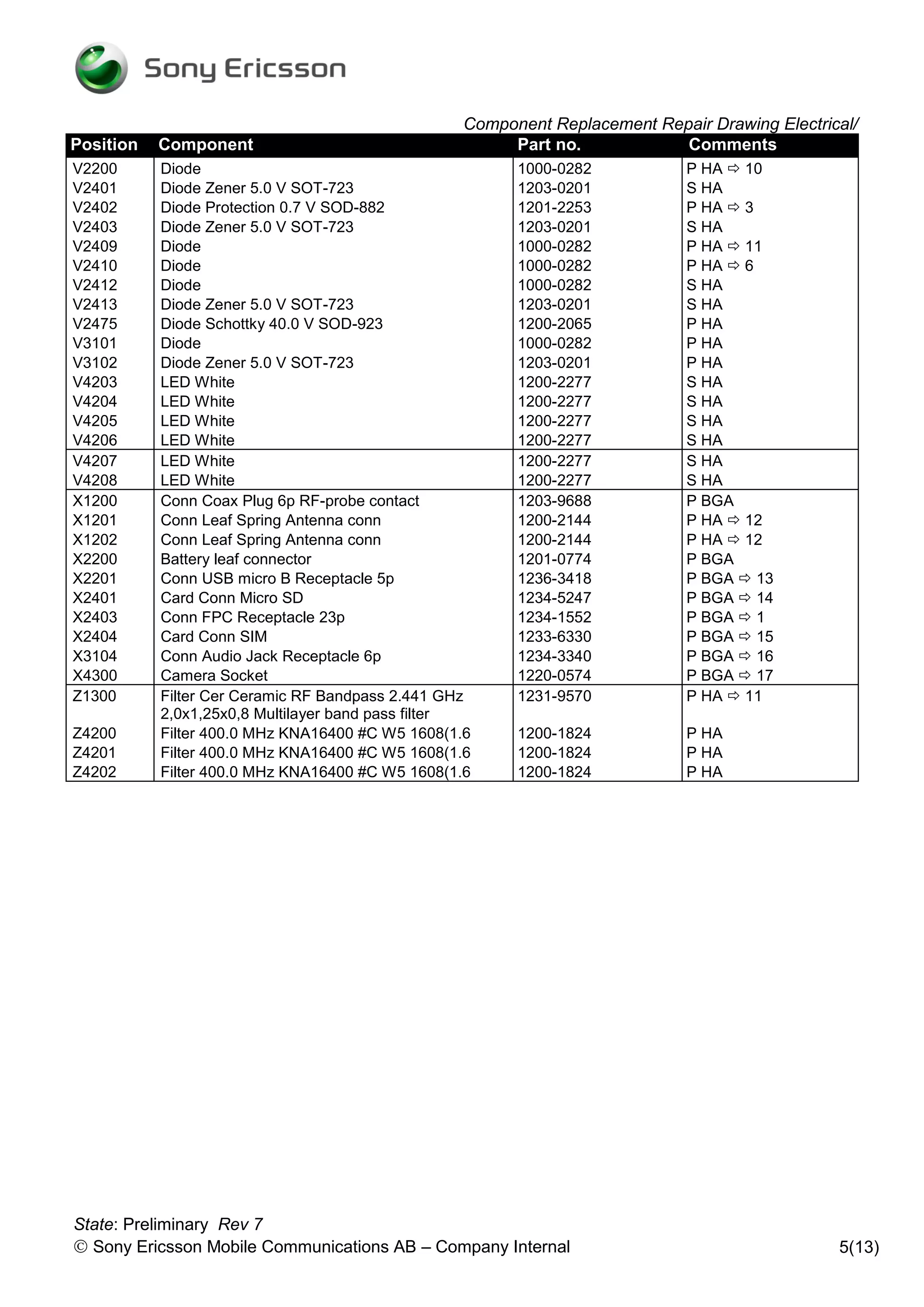
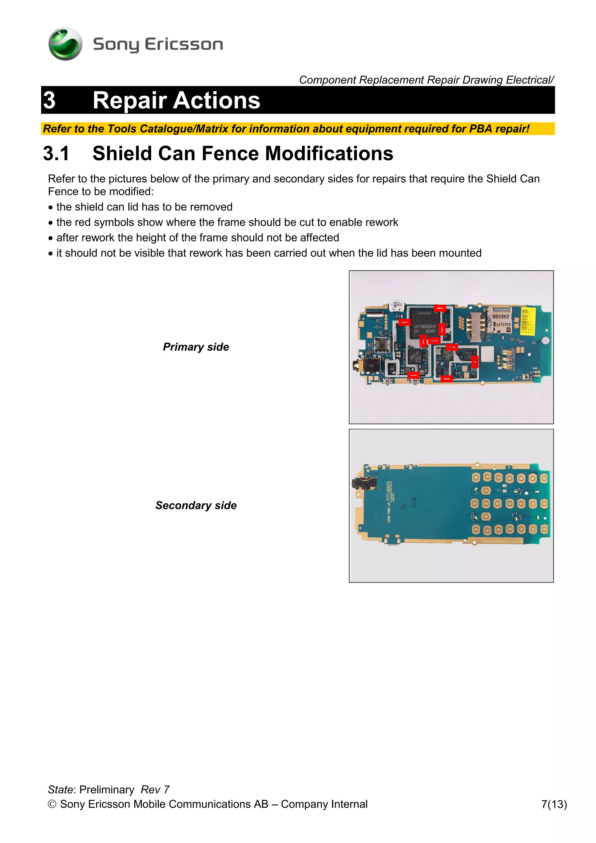
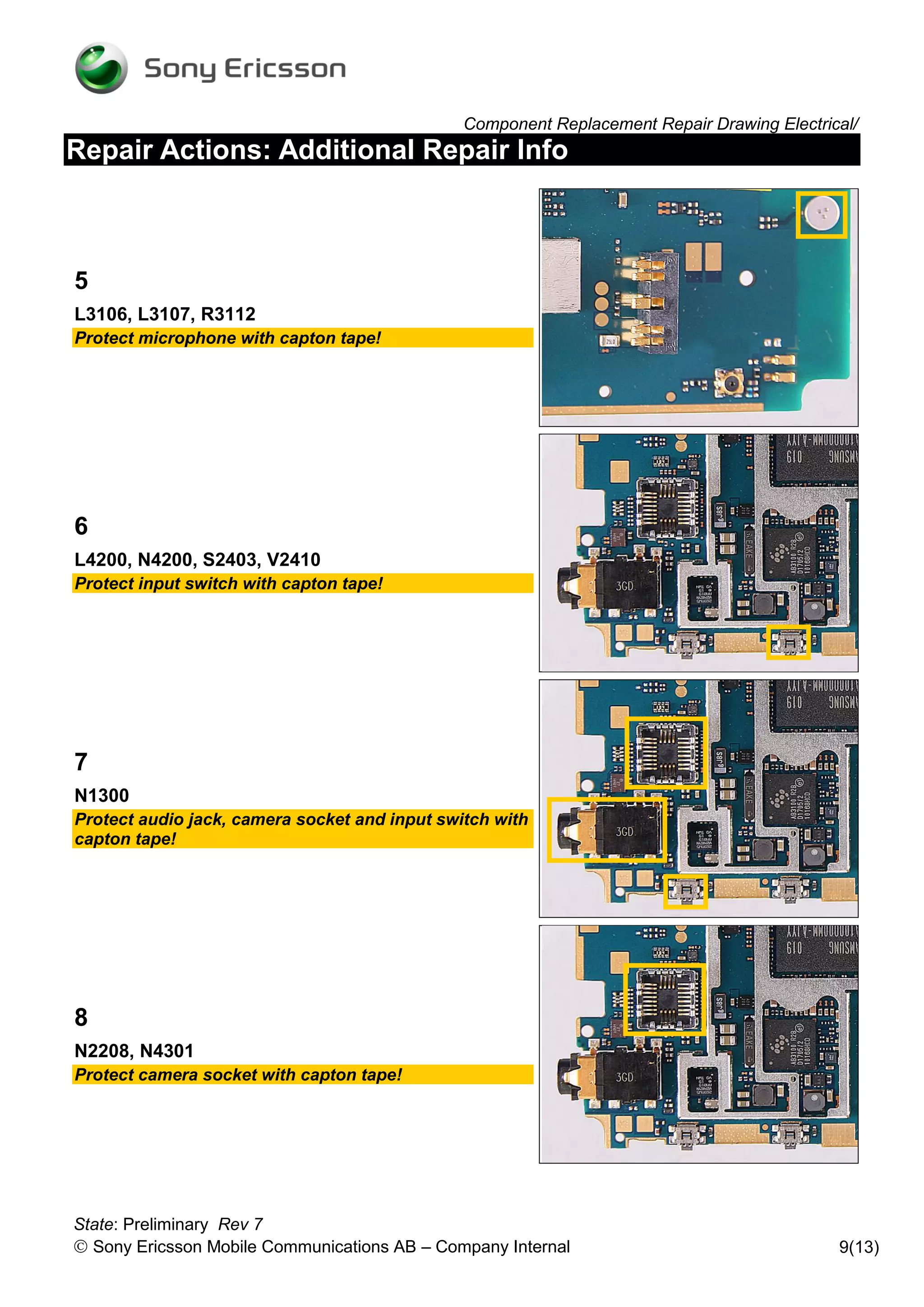
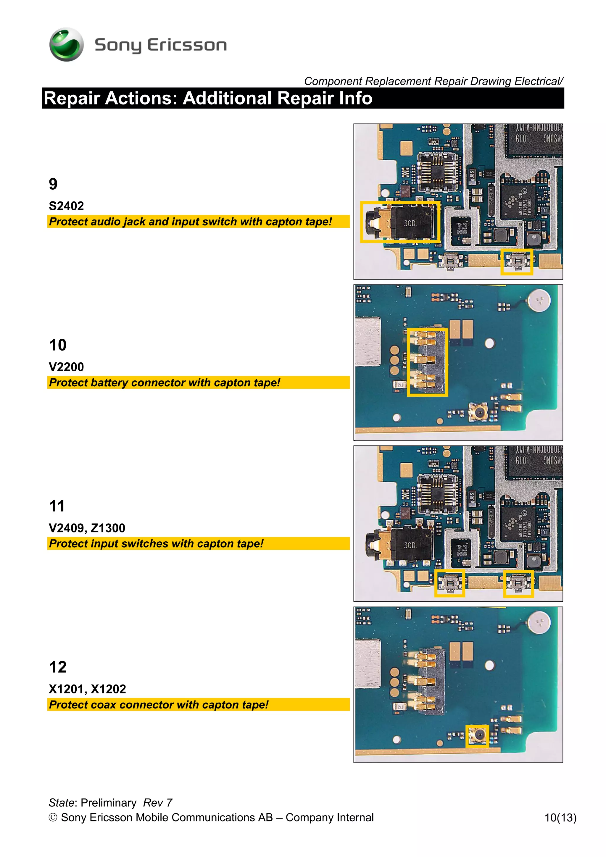
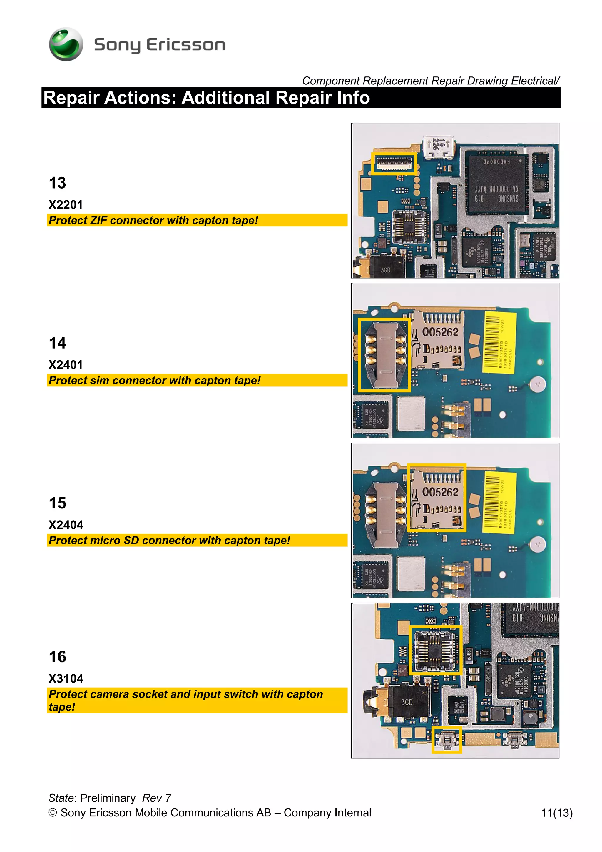
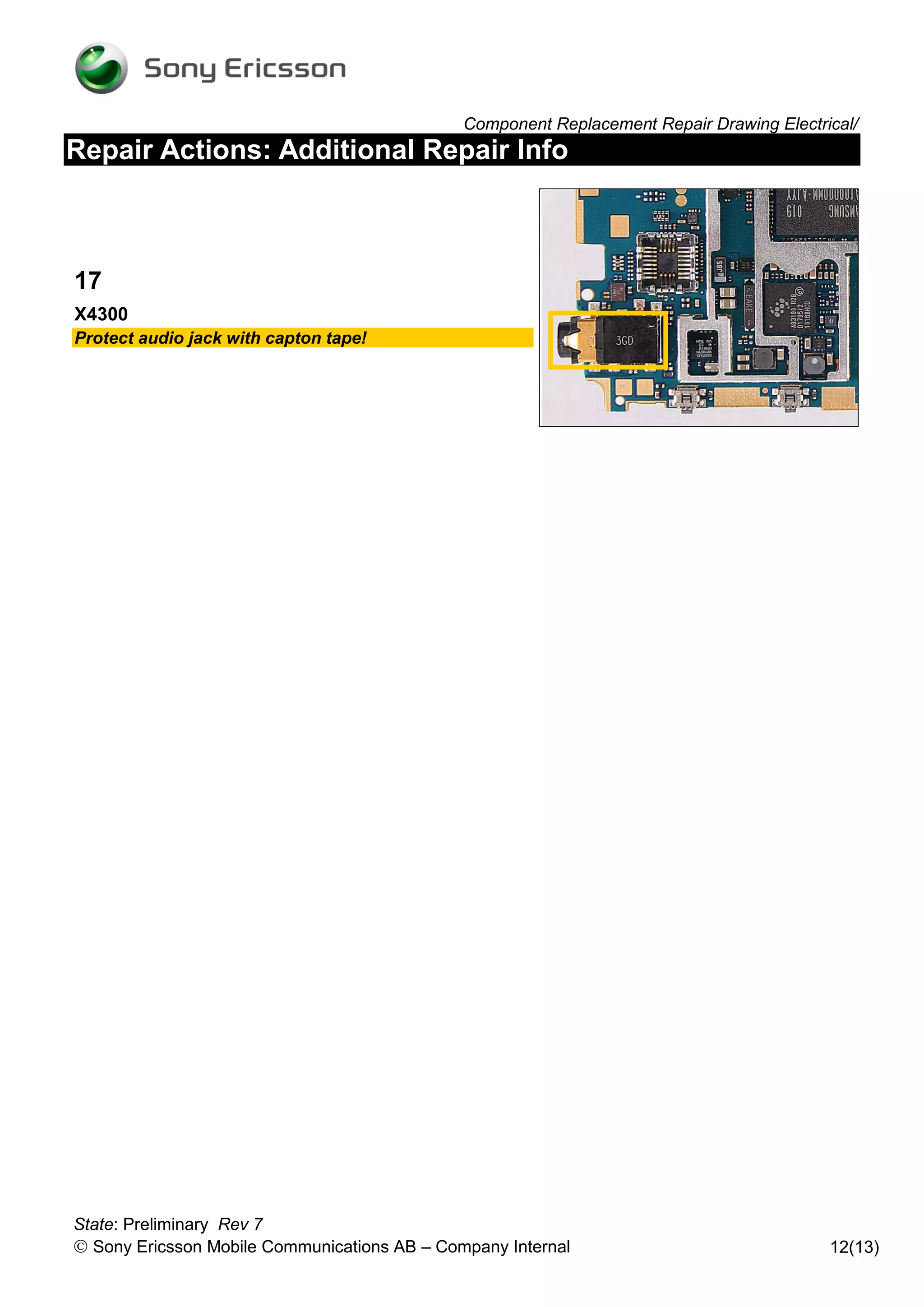
Component Replacement
                                 - electrical -


                                        Cedar
                                   J108i, J108a


State: Preliminary Rev 7
 Sony Ericsson Mobile Communications AB – Company Internal
Component Replacement Repair Drawing Electrical/
CONTENTS
1    Replaceable Components ............................................................. 3
2    Component Placing ........................................................................ 6
3    Repair Actions ................................................................................ 7
     3.1 Shield Can Fence Modifications ......................................................... 7
     3.2 Additional Repair Info .......................................................................... 8
4    Revision History ........................................................................... 13


For general information about electrical repair related issues, refer to
1220-1336: Generic Repair Manual - electrical


State: Preliminary Rev 7
 Sony Ericsson Mobile Communications AB – Company Internal                                              2(13)
Component Replacement Repair Drawing Electrical/

1         Replaceable Components
EXPLANATION OF ABBREVIATIONS USED IN THE COLUMN ‘COMMENTS’ BELOW
COMPONENT LOCATION
P = Primary side
S = Secondary side
MOISTURE SENSITIVITY LEVEL
MSLX (X = 1, 2, 2A, 3, 4, 5, 5A or 6)
For more information on moisture sensitivity levels:
Refer to 1220-1336: Generic Repair Manual – electrical, section ‘Moisture & Baking’!
REPAIR METHOD
HA = Hot Air (removal & mounting)
ST = Soldering Tool (removal & mounting)
HA/ST = Hot Air for removal - Soldering Tool for mounting
BGA = BGA Station
BH = Bottom Heater
ADDITIONAL INFORMATION
1 (2,3,4, etc.) = Proceed to ‘Additional Repair Info’ for further instructions in the indicated section(s).
CALIBRATION
C = Calibration of the phone is required after replacing the component
Calibration to be done by authorized centers only!


 State: Preliminary Rev 7
  Sony Ericsson Mobile Communications AB – Company Internal                                                   3(13)
Component Replacement Repair Drawing Electrical/
Position   Component                                       Part no.            Comments
B2100      Crystal 32.768 kHz                               1234-7322            P HA C
B300       Crystal 26.0 MHz 3225                            1200-0097            P HA C
B3101      Mic 4.0 Electret                                 1224-0804            P BGA
C2406      Capacitor Ceramic 1,0 uF +/-10% 25,0 V K         1000-0076            P HA  1
C4206      Capacitor Ceramic 1,0 uF +/-10% 25,0 V K         1000-0076            P HA
E3         Shield Can Closed                                1236-9150            P BGA
L1200      Ind Chip 2.2 uH 20% K2520                        1200-2028            P HA
L2200      Ind WW 4,7 uH 20% 3.0X3.0X1.0                    1200-2190            P HA
L2400      Ferrite Bead                                     1201-5128            P HA  2
L2401      Ferrite Bead                                     1201-5128            P HA  2
L2402      Ferrite Bead                                     1201-5128            P HA  2
L3303      Ind Chip 220.0 nH 5% K0402                       1000-3370            P HA  3
L3104      Filter 0.0 Hz 0402                               1001-1223            P HA
L3105      Ferrite B 1.5 kOhm 100.0 mA 0402                 1001-1223            P HA  4
L3106      Ferrite B 1.5 kOhm 100.0 mA 0402                 1001-1223            P HA  5
L3107      Ferrite B 1.5 kOhm 100.0 mA 0402                 1001-1223            P HA  5
L3108      Ferrite B 1.5 kOhm 100.0 mA 0402                 1001-1223            P HA
L3109      Ferrite B 1.5 kOhm 100.0 mA 0402                 1001-1223            P HA
L4200      Ind WW 4.7 uH +/-20% K3012                       1231-7059            P HA  6
N1210      IC Lin 16-pin WLP (2x2mm)                        1227-3531            P HA
N1211      IC Vreg PLP1820-6                                1204-5903            P HA
N1300      ASIC MS WLCSP61 STLC2690 Cut 4.1                 1230-5044            P HA  7
N200       Mod PA Quad-band                                 1210-8429            P BGA C
N2200      IC ESD Prot UDFN 6 2x2 mm                        1200-6309            P HA
N2208      IC Vreg PLP1820-6                                1235-2326            P HA  8
N2400      IC IF micro SMD 24 Bump                          1216-8174            P HA
N2420      Microcircuit/USB Transceiver and UART MU         1000-0350            P HA
N300       ASIC RF ZELDA HVQFN56                            1200-5290            P BGA C
N3100      IC Amplifier 500mA                               1203-4594            P HA
N3101      ASIC Tjatte3 CSP20                               1000-0198            P HA  2
N400       Module PA GSM                                    1200-0198            P BGA C(Band125)
N420       IC Amp                                           1200-9360            P HA C
N4200      Trans N-ch FET 1.6x1.6x0.55mm                    1235-2707            P HA  6
N4301      IC Vreg DFN 1212-6                               1226-5618            P HA  8
R2441      Resistor 33.0 Ohm +/-1% 50.0 mW K0201            1000-4091            P HA  1
R2444      Resistor 33.0 Ohm +/-1% 50.0 mW K0201            1000-4091            P HA  1
R3112      Varistor 10.0 MOhm S 50.0 mW 0402                1203-2250            P HA  5
S2402      Input Switch                                     1001-0060            P HA/ST  9
S2403      Input Switch                                     1001-0060            P HA/ST  6


State: Preliminary Rev 7
 Sony Ericsson Mobile Communications AB – Company Internal                                         4(13)
Component Replacement Repair Drawing Electrical/
Position   Component                                   Part no.            Comments
V2200      Diode                                        1000-0282            P HA  10
V2401      Diode Zener 5.0 V SOT-723                    1203-0201            S HA
V2402      Diode Protection 0.7 V SOD-882               1201-2253            P HA  3
V2403      Diode Zener 5.0 V SOT-723                    1203-0201            S HA
V2409      Diode                                        1000-0282            P HA  11
V2410      Diode                                        1000-0282            P HA  6
V2412      Diode                                        1000-0282            S HA
V2413      Diode Zener 5.0 V SOT-723                    1203-0201            S HA
V2475      Diode Schottky 40.0 V SOD-923                1200-2065            P HA
V3101      Diode                                        1000-0282            P HA
V3102      Diode Zener 5.0 V SOT-723                    1203-0201            P HA
V4203      LED White                                    1200-2277            S HA
V4204      LED White                                    1200-2277            S HA
V4205      LED White                                    1200-2277            S HA
V4206      LED White                                    1200-2277            S HA
V4207      LED White                                    1200-2277            S HA
V4208      LED White                                    1200-2277            S HA
X1200      Conn Coax Plug 6p RF-probe contact           1203-9688            P BGA
X1201      Conn Leaf Spring Antenna conn                1200-2144            P HA  12
X1202      Conn Leaf Spring Antenna conn                1200-2144            P HA  12
X2200      Battery leaf connector                       1201-0774            P BGA
X2201      Conn USB micro B Receptacle 5p               1236-3418            P BGA  13
X2401      Card Conn Micro SD                           1234-5247            P BGA  14
X2403      Conn FPC Receptacle 23p                      1234-1552            P BGA  1
X2404      Card Conn SIM                                1233-6330            P BGA  15
X3104      Conn Audio Jack Receptacle 6p                1234-3340            P BGA  16
X4300      Camera Socket                                1220-0574            P BGA  17
Z1300      Filter Cer Ceramic RF Bandpass 2.441 GHz     1231-9570            P HA  11
           2,0x1,25x0,8 Multilayer band pass filter
Z4200      Filter 400.0 MHz KNA16400 #C W5 1608(1.6     1200-1824            P HA
Z4201      Filter 400.0 MHz KNA16400 #C W5 1608(1.6     1200-1824            P HA
Z4202      Filter 400.0 MHz KNA16400 #C W5 1608(1.6     1200-1824            P HA


State: Preliminary Rev 7
 Sony Ericsson Mobile Communications AB – Company Internal                                    5(13)
Component Replacement Repair Drawing Electrical/

2        Component Placing
To access the Component Placing document, double-click the icon below.
Applicable for on-screen viewing only – icon not shown on hard-copies.


                          J108i                                      J108a


State: Preliminary Rev 7
 Sony Ericsson Mobile Communications AB – Company Internal                                   6(13)
Component Replacement Repair Drawing Electrical/

3        Repair Actions
Refer to the Tools Catalogue/Matrix for information about equipment required for PBA repair!

3.1      Shield Can Fence Modifications
Refer to the pictures below of the primary and secondary sides for repairs that require the Shield Can
Fence to be modified:
 the shield can lid has to be removed
 the red symbols show where the frame should be cut to enable rework
 after rework the height of the frame should not be affected
 it should not be visible that rework has been carried out when the lid has been mounted


                       Primary side


                      Secondary side


State: Preliminary Rev 7
 Sony Ericsson Mobile Communications AB – Company Internal                                              7(13)
Component Replacement Repair Drawing Electrical/
Repair Actions
3.2     Additional Repair Info


1
C2406, R2441, R2444, X2403
Protect USB connector with capton tape!


2
L2400, L2401, L2402, N3101
Protect audio jack and camera socket a with capton
tape!


3
L3303, V2402
Protect audio jack and input switch with capton tape!


4
L3105
Protect USB connector and ZIF connector with capton
tape!


State: Preliminary Rev 7
 Sony Ericsson Mobile Communications AB – Company Internal                                 8(13)
Component Replacement Repair Drawing Electrical/
Repair Actions: Additional Repair Info


5
L3106, L3107, R3112
Protect microphone with capton tape!


6
L4200, N4200, S2403, V2410
Protect input switch with capton tape!


7
N1300
Protect audio jack, camera socket and input switch with
capton tape!


8
N2208, N4301
Protect camera socket with capton tape!


State: Preliminary Rev 7
 Sony Ericsson Mobile Communications AB – Company Internal                                 9(13)
Component Replacement Repair Drawing Electrical/
Repair Actions: Additional Repair Info


9
S2402
Protect audio jack and input switch with capton tape!


10
V2200
Protect battery connector with capton tape!


11
V2409, Z1300
Protect input switches with capton tape!


12
X1201, X1202
Protect coax connector with capton tape!


State: Preliminary Rev 7
 Sony Ericsson Mobile Communications AB – Company Internal                                10(13)
Component Replacement Repair Drawing Electrical/
Repair Actions: Additional Repair Info


13
X2201
Protect ZIF connector with capton tape!


14
X2401
Protect sim connector with capton tape!


15
X2404
Protect micro SD connector with capton tape!


16
X3104
Protect camera socket and input switch with capton
tape!


State: Preliminary Rev 7
 Sony Ericsson Mobile Communications AB – Company Internal                                11(13)
Component Replacement Repair Drawing Electrical/
Repair Actions: Additional Repair Info


17
X4300
Protect audio jack with capton tape!


State: Preliminary Rev 7
 Sony Ericsson Mobile Communications AB – Company Internal                               12(13)
Component Replacement Repair Drawing Electrical/

4       Revision History
Rev.   Date            Changes / Comments
 1     2010-Sep-24     Initial release
 2     2010-Sep-26     Update the description of 1224-0804
 3     2010-Sep-26     Update the chapter 2
 4     2010-Oct-15     Change REP 621 102/33 to 1000-4091
 5     2010-Dec-1      Update the description of 1201-0774, 1201-2253, 1201-5128 and 1203-4594
 6     2011-2-21       Change the service level to electrical
 7     2011-3-2        Update some comment for calibration


State: Preliminary Rev 7
 Sony Ericsson Mobile Communications AB – Company Internal                                13(13)

J108 component replacement

  • 1.
    Component Replacement - electrical - Cedar J108i, J108a State: Preliminary Rev 7  Sony Ericsson Mobile Communications AB – Company Internal
  • 2.
    Component Replacement RepairDrawing Electrical/ CONTENTS 1 Replaceable Components ............................................................. 3 2 Component Placing ........................................................................ 6 3 Repair Actions ................................................................................ 7 3.1 Shield Can Fence Modifications ......................................................... 7 3.2 Additional Repair Info .......................................................................... 8 4 Revision History ........................................................................... 13 For general information about electrical repair related issues, refer to 1220-1336: Generic Repair Manual - electrical State: Preliminary Rev 7  Sony Ericsson Mobile Communications AB – Company Internal 2(13)
  • 3.
    Component Replacement RepairDrawing Electrical/ 1 Replaceable Components EXPLANATION OF ABBREVIATIONS USED IN THE COLUMN ‘COMMENTS’ BELOW COMPONENT LOCATION P = Primary side S = Secondary side MOISTURE SENSITIVITY LEVEL MSLX (X = 1, 2, 2A, 3, 4, 5, 5A or 6) For more information on moisture sensitivity levels: Refer to 1220-1336: Generic Repair Manual – electrical, section ‘Moisture & Baking’! REPAIR METHOD HA = Hot Air (removal & mounting) ST = Soldering Tool (removal & mounting) HA/ST = Hot Air for removal - Soldering Tool for mounting BGA = BGA Station BH = Bottom Heater ADDITIONAL INFORMATION 1 (2,3,4, etc.) = Proceed to ‘Additional Repair Info’ for further instructions in the indicated section(s). CALIBRATION C = Calibration of the phone is required after replacing the component Calibration to be done by authorized centers only! State: Preliminary Rev 7  Sony Ericsson Mobile Communications AB – Company Internal 3(13)
  • 4.
    Component Replacement RepairDrawing Electrical/ Position Component Part no. Comments B2100 Crystal 32.768 kHz 1234-7322 P HA C B300 Crystal 26.0 MHz 3225 1200-0097 P HA C B3101 Mic 4.0 Electret 1224-0804 P BGA C2406 Capacitor Ceramic 1,0 uF +/-10% 25,0 V K 1000-0076 P HA  1 C4206 Capacitor Ceramic 1,0 uF +/-10% 25,0 V K 1000-0076 P HA E3 Shield Can Closed 1236-9150 P BGA L1200 Ind Chip 2.2 uH 20% K2520 1200-2028 P HA L2200 Ind WW 4,7 uH 20% 3.0X3.0X1.0 1200-2190 P HA L2400 Ferrite Bead 1201-5128 P HA  2 L2401 Ferrite Bead 1201-5128 P HA  2 L2402 Ferrite Bead 1201-5128 P HA  2 L3303 Ind Chip 220.0 nH 5% K0402 1000-3370 P HA  3 L3104 Filter 0.0 Hz 0402 1001-1223 P HA L3105 Ferrite B 1.5 kOhm 100.0 mA 0402 1001-1223 P HA  4 L3106 Ferrite B 1.5 kOhm 100.0 mA 0402 1001-1223 P HA  5 L3107 Ferrite B 1.5 kOhm 100.0 mA 0402 1001-1223 P HA  5 L3108 Ferrite B 1.5 kOhm 100.0 mA 0402 1001-1223 P HA L3109 Ferrite B 1.5 kOhm 100.0 mA 0402 1001-1223 P HA L4200 Ind WW 4.7 uH +/-20% K3012 1231-7059 P HA  6 N1210 IC Lin 16-pin WLP (2x2mm) 1227-3531 P HA N1211 IC Vreg PLP1820-6 1204-5903 P HA N1300 ASIC MS WLCSP61 STLC2690 Cut 4.1 1230-5044 P HA  7 N200 Mod PA Quad-band 1210-8429 P BGA C N2200 IC ESD Prot UDFN 6 2x2 mm 1200-6309 P HA N2208 IC Vreg PLP1820-6 1235-2326 P HA  8 N2400 IC IF micro SMD 24 Bump 1216-8174 P HA N2420 Microcircuit/USB Transceiver and UART MU 1000-0350 P HA N300 ASIC RF ZELDA HVQFN56 1200-5290 P BGA C N3100 IC Amplifier 500mA 1203-4594 P HA N3101 ASIC Tjatte3 CSP20 1000-0198 P HA  2 N400 Module PA GSM 1200-0198 P BGA C(Band125) N420 IC Amp 1200-9360 P HA C N4200 Trans N-ch FET 1.6x1.6x0.55mm 1235-2707 P HA  6 N4301 IC Vreg DFN 1212-6 1226-5618 P HA  8 R2441 Resistor 33.0 Ohm +/-1% 50.0 mW K0201 1000-4091 P HA  1 R2444 Resistor 33.0 Ohm +/-1% 50.0 mW K0201 1000-4091 P HA  1 R3112 Varistor 10.0 MOhm S 50.0 mW 0402 1203-2250 P HA  5 S2402 Input Switch 1001-0060 P HA/ST  9 S2403 Input Switch 1001-0060 P HA/ST  6 State: Preliminary Rev 7  Sony Ericsson Mobile Communications AB – Company Internal 4(13)
  • 5.
    Component Replacement RepairDrawing Electrical/ Position Component Part no. Comments V2200 Diode 1000-0282 P HA  10 V2401 Diode Zener 5.0 V SOT-723 1203-0201 S HA V2402 Diode Protection 0.7 V SOD-882 1201-2253 P HA  3 V2403 Diode Zener 5.0 V SOT-723 1203-0201 S HA V2409 Diode 1000-0282 P HA  11 V2410 Diode 1000-0282 P HA  6 V2412 Diode 1000-0282 S HA V2413 Diode Zener 5.0 V SOT-723 1203-0201 S HA V2475 Diode Schottky 40.0 V SOD-923 1200-2065 P HA V3101 Diode 1000-0282 P HA V3102 Diode Zener 5.0 V SOT-723 1203-0201 P HA V4203 LED White 1200-2277 S HA V4204 LED White 1200-2277 S HA V4205 LED White 1200-2277 S HA V4206 LED White 1200-2277 S HA V4207 LED White 1200-2277 S HA V4208 LED White 1200-2277 S HA X1200 Conn Coax Plug 6p RF-probe contact 1203-9688 P BGA X1201 Conn Leaf Spring Antenna conn 1200-2144 P HA  12 X1202 Conn Leaf Spring Antenna conn 1200-2144 P HA  12 X2200 Battery leaf connector 1201-0774 P BGA X2201 Conn USB micro B Receptacle 5p 1236-3418 P BGA  13 X2401 Card Conn Micro SD 1234-5247 P BGA  14 X2403 Conn FPC Receptacle 23p 1234-1552 P BGA  1 X2404 Card Conn SIM 1233-6330 P BGA  15 X3104 Conn Audio Jack Receptacle 6p 1234-3340 P BGA  16 X4300 Camera Socket 1220-0574 P BGA  17 Z1300 Filter Cer Ceramic RF Bandpass 2.441 GHz 1231-9570 P HA  11 2,0x1,25x0,8 Multilayer band pass filter Z4200 Filter 400.0 MHz KNA16400 #C W5 1608(1.6 1200-1824 P HA Z4201 Filter 400.0 MHz KNA16400 #C W5 1608(1.6 1200-1824 P HA Z4202 Filter 400.0 MHz KNA16400 #C W5 1608(1.6 1200-1824 P HA State: Preliminary Rev 7  Sony Ericsson Mobile Communications AB – Company Internal 5(13)
  • 6.
    Component Replacement RepairDrawing Electrical/ 2 Component Placing To access the Component Placing document, double-click the icon below. Applicable for on-screen viewing only – icon not shown on hard-copies. J108i J108a State: Preliminary Rev 7  Sony Ericsson Mobile Communications AB – Company Internal 6(13)
  • 7.
    Component Replacement RepairDrawing Electrical/ 3 Repair Actions Refer to the Tools Catalogue/Matrix for information about equipment required for PBA repair! 3.1 Shield Can Fence Modifications Refer to the pictures below of the primary and secondary sides for repairs that require the Shield Can Fence to be modified:  the shield can lid has to be removed  the red symbols show where the frame should be cut to enable rework  after rework the height of the frame should not be affected  it should not be visible that rework has been carried out when the lid has been mounted Primary side Secondary side State: Preliminary Rev 7  Sony Ericsson Mobile Communications AB – Company Internal 7(13)
  • 8.
    Component Replacement RepairDrawing Electrical/ Repair Actions 3.2 Additional Repair Info 1 C2406, R2441, R2444, X2403 Protect USB connector with capton tape! 2 L2400, L2401, L2402, N3101 Protect audio jack and camera socket a with capton tape! 3 L3303, V2402 Protect audio jack and input switch with capton tape! 4 L3105 Protect USB connector and ZIF connector with capton tape! State: Preliminary Rev 7  Sony Ericsson Mobile Communications AB – Company Internal 8(13)
  • 9.
    Component Replacement RepairDrawing Electrical/ Repair Actions: Additional Repair Info 5 L3106, L3107, R3112 Protect microphone with capton tape! 6 L4200, N4200, S2403, V2410 Protect input switch with capton tape! 7 N1300 Protect audio jack, camera socket and input switch with capton tape! 8 N2208, N4301 Protect camera socket with capton tape! State: Preliminary Rev 7  Sony Ericsson Mobile Communications AB – Company Internal 9(13)
  • 10.
    Component Replacement RepairDrawing Electrical/ Repair Actions: Additional Repair Info 9 S2402 Protect audio jack and input switch with capton tape! 10 V2200 Protect battery connector with capton tape! 11 V2409, Z1300 Protect input switches with capton tape! 12 X1201, X1202 Protect coax connector with capton tape! State: Preliminary Rev 7  Sony Ericsson Mobile Communications AB – Company Internal 10(13)
  • 11.
    Component Replacement RepairDrawing Electrical/ Repair Actions: Additional Repair Info 13 X2201 Protect ZIF connector with capton tape! 14 X2401 Protect sim connector with capton tape! 15 X2404 Protect micro SD connector with capton tape! 16 X3104 Protect camera socket and input switch with capton tape! State: Preliminary Rev 7  Sony Ericsson Mobile Communications AB – Company Internal 11(13)
  • 12.
    Component Replacement RepairDrawing Electrical/ Repair Actions: Additional Repair Info 17 X4300 Protect audio jack with capton tape! State: Preliminary Rev 7  Sony Ericsson Mobile Communications AB – Company Internal 12(13)
  • 13.
    Component Replacement RepairDrawing Electrical/ 4 Revision History Rev. Date Changes / Comments 1 2010-Sep-24 Initial release 2 2010-Sep-26 Update the description of 1224-0804 3 2010-Sep-26 Update the chapter 2 4 2010-Oct-15 Change REP 621 102/33 to 1000-4091 5 2010-Dec-1 Update the description of 1201-0774, 1201-2253, 1201-5128 and 1203-4594 6 2011-2-21 Change the service level to electrical 7 2011-3-2 Update some comment for calibration State: Preliminary Rev 7  Sony Ericsson Mobile Communications AB – Company Internal 13(13)