Download to read offline

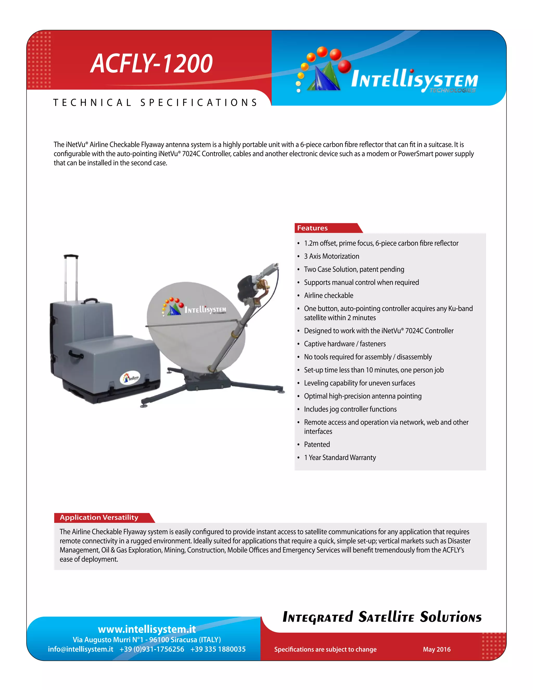

The InetVU® airline checkable flyaway antenna system is a portable satellite communication solution designed for rapid deployment in rugged environments, featuring a 6-piece carbon fiber reflector. It supports auto-pointing with the InetVU® 7024c controller, allowing access to ku-band satellites in under two minutes. Ideal for various industries such as disaster management and mobile offices, the system offers easy setup with no tools required and operates across a wide environmental range.


