Download as PDF, PPTX
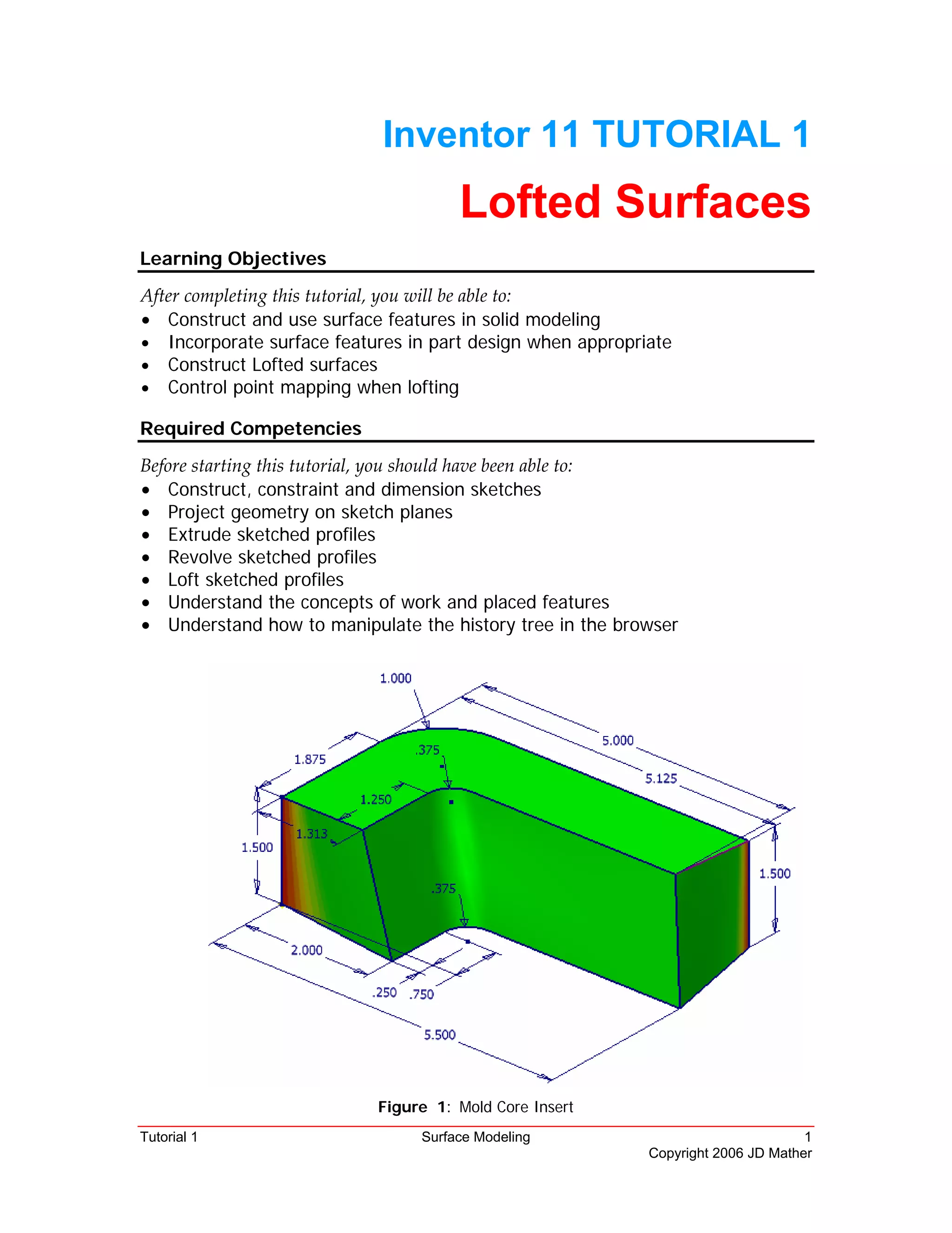
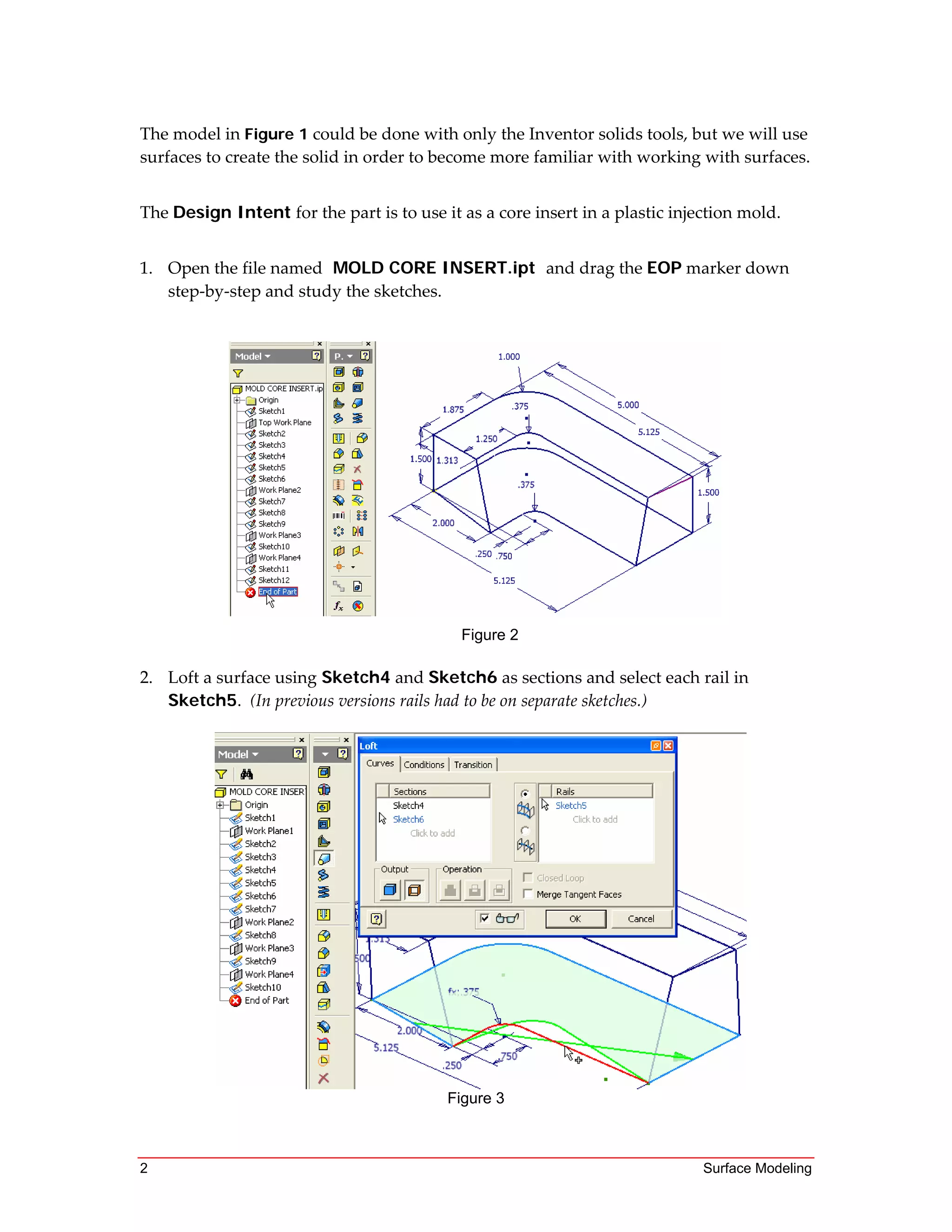
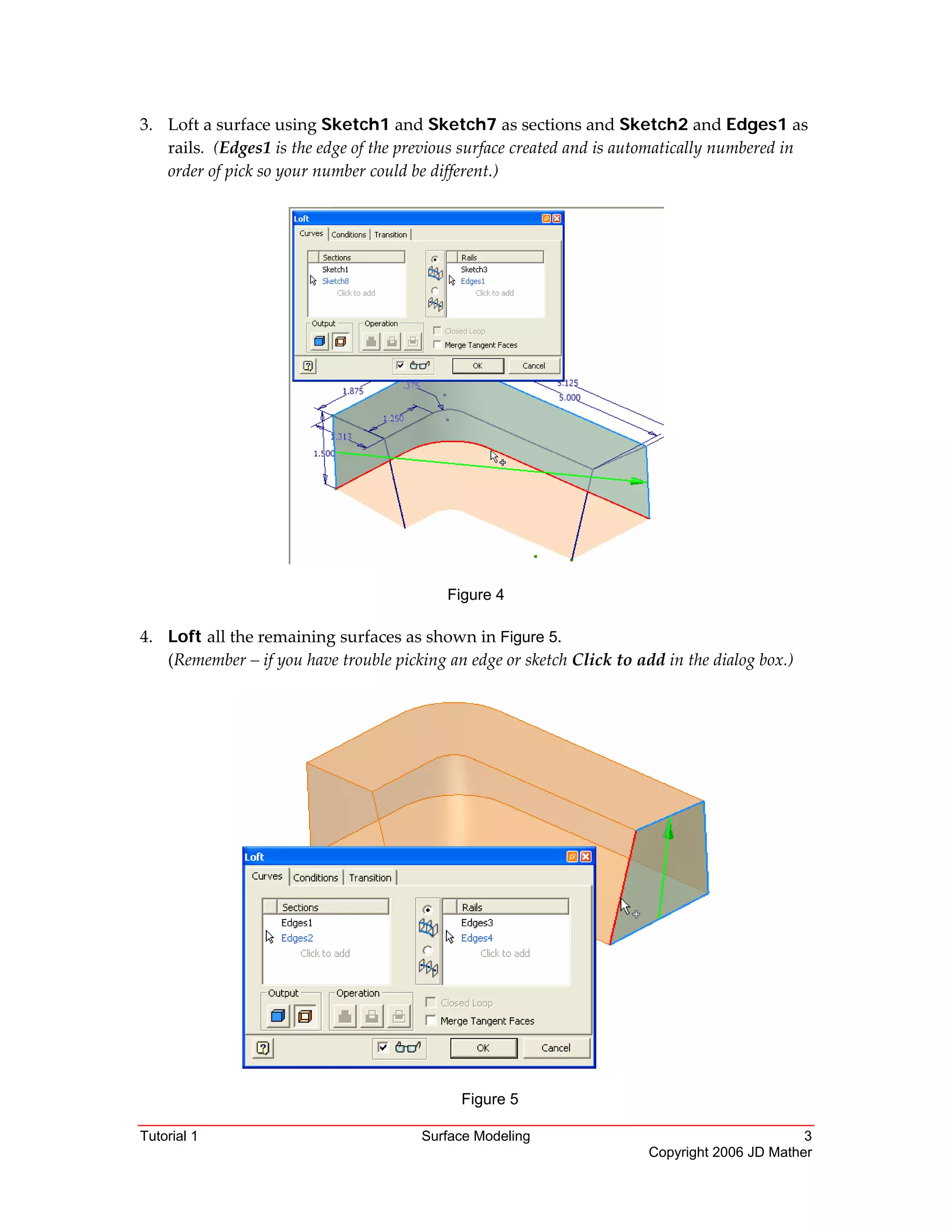
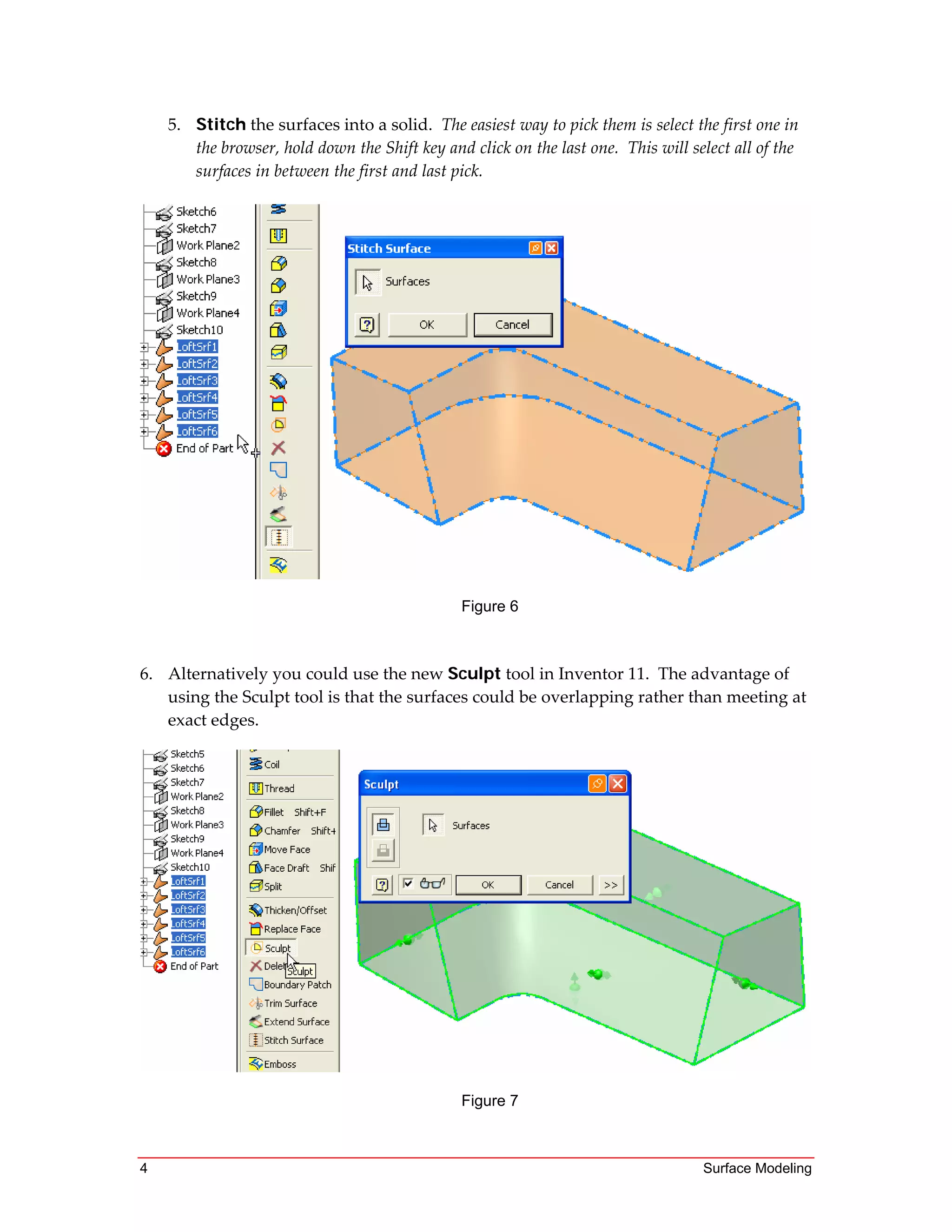

This tutorial teaches how to construct lofted surfaces in Inventor. It demonstrates how to loft surfaces using sketches as sections and edges or rails for control. The tutorial models a mold core insert using lofted surfaces that are then stitched together into a solid. It also shows how to check and manually map control points when lofting.


![Inventor notes[1]](https://cdn.slidesharecdn.com/ss_thumbnails/inventornotes1-160125233002-thumbnail.jpg?width=640&height=640&fit=bounds)


