Here are some key industries and products that rely on injection molding:
- Automotive: car parts like bumpers, dashboards, steering wheels
- Consumer goods: toys, bottles, containers, appliances like hair dryers
- Electronics: phone/laptop cases, computer components
- Medical: syringes, valves, implants
- Packaging: crates, bins, buckets
This document provides information about dental casting procedures and defects. It discusses the history of casting, outlines the main steps including spruing, investing, burnout and casting. Spruing involves attaching a sprue former made of wax, plastic or metal to direct molten metal into the mold. Investing is the process of enveloping the wax pattern with investment material. Burnout involves slowly heating the mold to eliminate wax. Casting involves melting dental alloys and directing the molten metal into the mold using various casting machines and techniques. The document also discusses potential casting defects.
This document discusses how isotropic mass finishing processes can improve part performance and service life. It begins by describing how many manufacturers still rely on outdated manual deburring methods instead of considering edge and surface finishing during initial planning. This leads to higher costs when parts fail quality standards due to burrs or surfaces. The document then explains how mass finishing processes can produce uniform, isotropic surface textures with compressive residual stresses. This improves part wear resistance, fatigue life, and consistency compared to directional textures from machining. Specifically, isotropic mass finishing can produce negatively skewed, plateaued surfaces instead of positively skewed surfaces from other processes. It concludes that these surface alterations from mass finishing often improve part performance in unexpected ways.
• The production department contains many different problems in the production process that involves the performance and quality of the products.
• For plastics factories there are many problems that arise in products that cause a decline in production levels resulting in loss of funds and raw materials and a waste of available capabilities.
The presentation summarizes a group project to design an electrical outlet clamp. It discusses the motivation for the product, key features and benefits including its locking mechanism. It then reviews the injection molding and assembly manufacturing processes used, outlining the main steps. Some initial prototypes encountered problems fitting parts and sourcing materials that required modifications. The presentation concludes thanking the audience.
This document discusses the benefits of isotropic mass finishing for improving surface integrity and part performance. It describes how many manufacturers still rely on outdated manual deburring and finishing methods instead of considering these processes during initial engineering and planning. This can lead to high costs when parts fail quality standards due to surface issues. The document advocates for including isotropic mass finishing solutions, such as barrel, vibratory, and centrifugal finishing, earlier in the design process to reduce costs and improve part consistency, edge contour, surface smoothness, and performance.
NEW SolidWorks® Plastics
Injection molding simulation for designers of plastic parts and injection molds. Evaluate the manufacturability of parts and molds while designing for form, fit, and function.
For Plastic Part Designers
Part designers get rapid feedback on how modifications to wall thickness, gate locations, materials, or geometry can affect the manufacturing of their part
For Mold Designers
Quickly create and analyze single, multi-cavity, and family mold layouts, including sprues, runners, and gates.
Getting the Right Results
The Results Adviser provides practical design advice and troubleshooting tips to help diagnose and solve potential problems.
Masking a printed circuit board for the conformal coating process can be an easy task. However, many circuits can be damaged beyond repair if you get it wrong.
Understand the fundamentals of conformal coating masking, what different materials are available, the problems associated with these masking products and how to get the best out of your process.
WELDLINE STRENGTH ANALYSIS THEORETICAL PREDICTIVE MODEL WITH THE USE OF MOLDL...IRJET Journal
Weld lines, also called knit lines, are defects that occur when melt flows collide in an injection mold. They can weaken parts. This document presents a predictive model for analyzing weld line strength using Moldflow simulation. It describes how weld lines form from fountain flow and discusses parameters like gate location, temperature, and pressure that influence strength. A case study applies the method to a component that was breaking. Moldflow identified stresses, which were input to structural analysis. Modified gate location and ribs increased strength and safety factor. The model allows objective weld line strength prediction to avoid defects.
CASTING DEFECTS ANALYSIS OF SWASH PLATE (PVB10 YOKE) USING SIMULATIONIRJET Journal
This document discusses using casting simulation software to analyze and reduce defects in castings of a swash plate component (PVB10 Yoke). It conducted four trials over multiple months: the first using traditional methods resulted in 42.5% rejection due to shrinkage porosity and other defects. The second trial placed a core but rejection remained high. The third trial used casting simulation software which identified riser size as the cause of shrinkage porosity. The fourth trial increased riser size, resulting in only 5% rejection. Using simulation enabled identifying the root cause of defects and reducing the rejection rate from 42.5% to 5% for the swash plate casting.
Get faster design success eliminating mistakes and proyect bugs by preventive use of DFMEA preventive and corrective actions. Practical experiences and tips
This article discusses adhesive bond failure modes on polypropylene. There are three main failure modes: adhesion failure at the interface between the adhesive and substrate, cohesion failure within the adhesive layer, and mixed mode failure exhibiting characteristics of both. To determine the cause, it is important to identify which failure mode is occurring. Adhesion failures usually originate in manufacturing, while cohesion failures can be from joint design issues or material properties. Once the failure mode is identified, the solution becomes clearer whether to examine manufacturing processes or product design.
This document discusses a study comparing the use of solid and shell material models in stamping simulation. Shell elements are commonly used due to shorter simulation times but cannot predict thinning or folding strains. The study models a deep drawing process with both shell and solid elements. Shell element simulation took 2.5 hours while solid element simulation was not completed after 20 hours. Results show plastic strains within failure limits for shell elements but solid element results cannot be viewed in the visualization software. Further work is needed to optimize solid element simulations.
The document provides a table of contents for sections on modelling, process planning, NC machining, and literature search on CAD/CAM technologies for tooling and dies. It then summarizes the modelling of a remote control car part in Pro/Engineer including sketches, extrusion, shell creation, and hole features. The process planning section outlines creating a process plan table for NC milling operations on the cavity and core including operation descriptions, tools, machining parameters and clearances. Finally, the NC machining section describes creating the mould components from the model and performing draft checks on the core and cavity parts.
Autodesk Moldflow Insight software provides injection molding simulation tools to validate and optimize plastic parts and molds. It helps predict flow, defects, warpage and more to reduce costs and speed production. The software imports CAD files, simulates filling, packing and cooling, and provides tools to evaluate results and automate reporting.
The document discusses design for manufacturing (DFM) and design for assembly (DFA). It states that DFM aims to minimize production costs and time to market while maintaining quality. DFA focuses on simplifying assembly directions and methods. The benefits of DFM and DFA include reduced costs from lower part counts, increased reliability and quality from simplified production processes. Guidelines for DFM and DFA include minimizing part counts, using modular designs, and designing for ease of assembly and manufacturing. It also provides guidelines for various manufacturing processes like injection molding, rotational molding, sheet metal forming, and casting.
This document discusses using design layout data to improve defect identification and reduce new product introduction cycle times. It outlines a solution of using design-based inspection and binning techniques with lithography and inspection tools. This integrated approach allows more automated and sensitive inspection recipes, faster separation of systematic and random defects, and clearer identification of process-limiting structures to help maintain and improve yield at high volume production. A customer testimonial notes how using CAD-based inspection has improved defect management efficiency and reduced optimization cycle times.
This document provides an overview of an organizational study conducted at Bilva Moulds Pvt Ltd in Bangalore. It discusses the company's profile, including that it was established in 2005 and manufactures plastic injection moulds and components. It also outlines the objectives of the study, which are to understand the company profile, vision, mission, organizational activities, and SWOT analysis. The document then provides details on the plastic injection moulding industry history and Bilva Moulds' product range and quality testing processes.
The document summarizes a presentation on fracture-fatigue simulation using meshfree methods. The objectives are to study stress distribution in cracked components using meshfree methods, analyze crack growth, and simulate stress intensity factors and J-integrals. Meshfree methods represent domains using nodes without elements, allowing selective node placement. They will be used to simulate fracture and fatigue crack propagation.
IRJET- Weld Defects and their Implications on Weld StructureIRJET Journal
The document discusses weld defects, their classification, and non-destructive testing methods to identify them. It describes two types of weld defects - external defects like cracks, undercuts, spatter, porosity, overlap and craters, and internal defects like slag inclusions, incomplete fusion, and necklace cracking. The most common non-destructive testing method discussed is dye penetrant inspection, which involves pre-cleaning, applying penetrant, removing excess penetrant, applying developer, and inspecting to identify surface-breaking defects in welds.
WQD2011 - KAIZEN - EMAL - To eliminate the chances of breaking of PC charging...Dubai Quality Group
Kaizen case study submitted by Emirates Aluminium during 3rd Continual Improvement & Innovation Symposium organized by Dubai Quality Group's Continual Improvement Subgroup to celebrate World Quality Day 2011.
Click2Cast is casting simulation software that allows users to optimize cast component designs in 5 simple steps. It provides accurate simulations with fast meshing and solve times. New features in version 4.0 include support for multi-material components as well as process templates for investment casting. Click2Cast helps identify and correct typical casting defects such as porosity, air entrapment, and missruns. It can be incorporated into the traditional design process to efficiently optimize designs and avoid defects without extensive learning or high prices.
Chetankumar K Jotawar is a mechanical engineer with over 5 years of experience in product design and development. He has expertise in CAD modeling software like Catia and Unigraphics. His experience includes projects in foundry tooling design, 3D modeling, pattern development, and cost reduction. He holds an MTech in Product Design and Manufacturing and is proficient in technical skills like CAD, FEA, and programming languages.
When I searched for the recent technology and developments in SLA/ DLP printers, I found limited resources that speaks about the existing problems, but there is ample of resources that talk about the technology and its basics. Very limited open source material is available online related to this topics. A candidate without the firsthand experience of these printers will never be able to understand the limitations. Hence these efforts are made to make the problem statement more open source to the people who cannot actually have the privilege to experience such printers first hand. This paper talks about the normal problems one faces while operating this printer, cautions and maintenance aspects I hope all the information provided in this report shall and will be used for the development of existing technology.
My name is Elena Long. I am associated with matlabassignmentexperts.com as an Matlab Assignment help expert for the past 4 years and have been helping students with their assignments. I have a Ph.D. in Mechanical Engineering, from McGill University, Canada.
Engineering Guidelines to Designing Plastic Parts for Injection MoldingJaycon Systems
At Jaycon Systems, we have chosen to use injection molding as the main manufacturing process to bring plastic products to life.
However, injection molding is not simple. Engaging in such process requires an extensive knowledge about its machinery and process.
In this presentation, we will show you some of the aspects we take into consideration when designing plastic parts for injection molding so we can save our customers time and money in the long run.
More Related Content
Similar to Injection Molded Part Problems and Solutions
WELDLINE STRENGTH ANALYSIS THEORETICAL PREDICTIVE MODEL WITH THE USE OF MOLDL...IRJET Journal
Weld lines, also called knit lines, are defects that occur when melt flows collide in an injection mold. They can weaken parts. This document presents a predictive model for analyzing weld line strength using Moldflow simulation. It describes how weld lines form from fountain flow and discusses parameters like gate location, temperature, and pressure that influence strength. A case study applies the method to a component that was breaking. Moldflow identified stresses, which were input to structural analysis. Modified gate location and ribs increased strength and safety factor. The model allows objective weld line strength prediction to avoid defects.
CASTING DEFECTS ANALYSIS OF SWASH PLATE (PVB10 YOKE) USING SIMULATIONIRJET Journal
This document discusses using casting simulation software to analyze and reduce defects in castings of a swash plate component (PVB10 Yoke). It conducted four trials over multiple months: the first using traditional methods resulted in 42.5% rejection due to shrinkage porosity and other defects. The second trial placed a core but rejection remained high. The third trial used casting simulation software which identified riser size as the cause of shrinkage porosity. The fourth trial increased riser size, resulting in only 5% rejection. Using simulation enabled identifying the root cause of defects and reducing the rejection rate from 42.5% to 5% for the swash plate casting.
Get faster design success eliminating mistakes and proyect bugs by preventive use of DFMEA preventive and corrective actions. Practical experiences and tips
This article discusses adhesive bond failure modes on polypropylene. There are three main failure modes: adhesion failure at the interface between the adhesive and substrate, cohesion failure within the adhesive layer, and mixed mode failure exhibiting characteristics of both. To determine the cause, it is important to identify which failure mode is occurring. Adhesion failures usually originate in manufacturing, while cohesion failures can be from joint design issues or material properties. Once the failure mode is identified, the solution becomes clearer whether to examine manufacturing processes or product design.
This document discusses a study comparing the use of solid and shell material models in stamping simulation. Shell elements are commonly used due to shorter simulation times but cannot predict thinning or folding strains. The study models a deep drawing process with both shell and solid elements. Shell element simulation took 2.5 hours while solid element simulation was not completed after 20 hours. Results show plastic strains within failure limits for shell elements but solid element results cannot be viewed in the visualization software. Further work is needed to optimize solid element simulations.
The document provides a table of contents for sections on modelling, process planning, NC machining, and literature search on CAD/CAM technologies for tooling and dies. It then summarizes the modelling of a remote control car part in Pro/Engineer including sketches, extrusion, shell creation, and hole features. The process planning section outlines creating a process plan table for NC milling operations on the cavity and core including operation descriptions, tools, machining parameters and clearances. Finally, the NC machining section describes creating the mould components from the model and performing draft checks on the core and cavity parts.
Autodesk Moldflow Insight software provides injection molding simulation tools to validate and optimize plastic parts and molds. It helps predict flow, defects, warpage and more to reduce costs and speed production. The software imports CAD files, simulates filling, packing and cooling, and provides tools to evaluate results and automate reporting.
The document discusses design for manufacturing (DFM) and design for assembly (DFA). It states that DFM aims to minimize production costs and time to market while maintaining quality. DFA focuses on simplifying assembly directions and methods. The benefits of DFM and DFA include reduced costs from lower part counts, increased reliability and quality from simplified production processes. Guidelines for DFM and DFA include minimizing part counts, using modular designs, and designing for ease of assembly and manufacturing. It also provides guidelines for various manufacturing processes like injection molding, rotational molding, sheet metal forming, and casting.
This document discusses using design layout data to improve defect identification and reduce new product introduction cycle times. It outlines a solution of using design-based inspection and binning techniques with lithography and inspection tools. This integrated approach allows more automated and sensitive inspection recipes, faster separation of systematic and random defects, and clearer identification of process-limiting structures to help maintain and improve yield at high volume production. A customer testimonial notes how using CAD-based inspection has improved defect management efficiency and reduced optimization cycle times.
This document provides an overview of an organizational study conducted at Bilva Moulds Pvt Ltd in Bangalore. It discusses the company's profile, including that it was established in 2005 and manufactures plastic injection moulds and components. It also outlines the objectives of the study, which are to understand the company profile, vision, mission, organizational activities, and SWOT analysis. The document then provides details on the plastic injection moulding industry history and Bilva Moulds' product range and quality testing processes.
The document summarizes a presentation on fracture-fatigue simulation using meshfree methods. The objectives are to study stress distribution in cracked components using meshfree methods, analyze crack growth, and simulate stress intensity factors and J-integrals. Meshfree methods represent domains using nodes without elements, allowing selective node placement. They will be used to simulate fracture and fatigue crack propagation.
IRJET- Weld Defects and their Implications on Weld StructureIRJET Journal
The document discusses weld defects, their classification, and non-destructive testing methods to identify them. It describes two types of weld defects - external defects like cracks, undercuts, spatter, porosity, overlap and craters, and internal defects like slag inclusions, incomplete fusion, and necklace cracking. The most common non-destructive testing method discussed is dye penetrant inspection, which involves pre-cleaning, applying penetrant, removing excess penetrant, applying developer, and inspecting to identify surface-breaking defects in welds.
WQD2011 - KAIZEN - EMAL - To eliminate the chances of breaking of PC charging...Dubai Quality Group
Kaizen case study submitted by Emirates Aluminium during 3rd Continual Improvement & Innovation Symposium organized by Dubai Quality Group's Continual Improvement Subgroup to celebrate World Quality Day 2011.
Click2Cast is casting simulation software that allows users to optimize cast component designs in 5 simple steps. It provides accurate simulations with fast meshing and solve times. New features in version 4.0 include support for multi-material components as well as process templates for investment casting. Click2Cast helps identify and correct typical casting defects such as porosity, air entrapment, and missruns. It can be incorporated into the traditional design process to efficiently optimize designs and avoid defects without extensive learning or high prices.
Chetankumar K Jotawar is a mechanical engineer with over 5 years of experience in product design and development. He has expertise in CAD modeling software like Catia and Unigraphics. His experience includes projects in foundry tooling design, 3D modeling, pattern development, and cost reduction. He holds an MTech in Product Design and Manufacturing and is proficient in technical skills like CAD, FEA, and programming languages.
When I searched for the recent technology and developments in SLA/ DLP printers, I found limited resources that speaks about the existing problems, but there is ample of resources that talk about the technology and its basics. Very limited open source material is available online related to this topics. A candidate without the firsthand experience of these printers will never be able to understand the limitations. Hence these efforts are made to make the problem statement more open source to the people who cannot actually have the privilege to experience such printers first hand. This paper talks about the normal problems one faces while operating this printer, cautions and maintenance aspects I hope all the information provided in this report shall and will be used for the development of existing technology.
My name is Elena Long. I am associated with matlabassignmentexperts.com as an Matlab Assignment help expert for the past 4 years and have been helping students with their assignments. I have a Ph.D. in Mechanical Engineering, from McGill University, Canada.
Engineering Guidelines to Designing Plastic Parts for Injection MoldingJaycon Systems
At Jaycon Systems, we have chosen to use injection molding as the main manufacturing process to bring plastic products to life.
However, injection molding is not simple. Engaging in such process requires an extensive knowledge about its machinery and process.
In this presentation, we will show you some of the aspects we take into consideration when designing plastic parts for injection molding so we can save our customers time and money in the long run.
Similar to Injection Molded Part Problems and Solutions (20)
Engineering Guidelines to Designing Plastic Parts for Injection Molding
Injection Molded Part Problems and Solutions
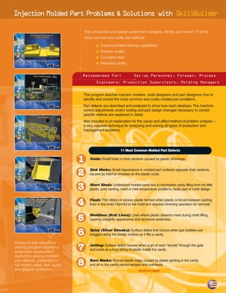
1. Inject on Mo ded Part Problems & Solutions with SkillBuilder
i l
Train production and design personnel to analyze, identify and correct 11 of the
most common and costly part defects!
N Expand problem-solving capabilities
N Improve quality
N Cut reject rates
N Maximize profits
Recommended For: Set-up Personnel, Foremen, Process
Engineers, Production Supervisors, Molding Managers
This program teaches injection molders, mold designers and part designers how to
identify and correct the most common and costly molded part problems.
Part defects are described and analyzed to show how each develops. The machine
control adjustments and/or tooling and part design changes necessary to correct
specific defects are explained in detail.
Also included is an explanation for the cause and effect method of problem analysis –
a very valuable technique for analyzing and solving all types of production and
management problems.
11 Most Common Molded Part Defects
1 Voids: Small holes in thick sections caused by plastic shrinkage.
2 Sink Marks: Small depressions in molded part surfaces opposite thick sections,
caused by internal stresses as the plastic cools.
3 Short Shots: Undersized molded parts due to incomplete cavity filling from too little
plastic, poor venting, mold or melt temperature problems, faulty part or mold design.
Lessons
4 Flash: Thin ribbon of excess plastic formed when plastic is forced between parting
lines in the mold. Harmful to the mold and requires trimming operation for removal.
5 Weldlines (Knit Lines): Lines where plastic streams meet during mold filling,
causing unsightly appearance and structural weakness.
6 Splay (Silver Streaks): Surface defect that occurs when gas bubbles are
dragged along the plastic surface as it fills a cavity.
7
Paulson’s fully interactive
Jetting: Surface defect caused when a jet of resin “shoots” through the gate
training program applies a
and cools as a long string of plastic inside the cavity.
systematic cause-effect
method to solving molded
part defects, presented in
full motion video, text, audio 8 Burn Marks: Burned plastic edge caused by plastic igniting in the cavity,
and air in the cavity cannot escape and overheats.
and graphic animation. (cont'd on back)
2. Injection Molded Part Problems & Solutions with SkillBuilder
11 Most Common Molded Part Defects (cont’d)
9 Warp: Molded part distortions from uneven stresses in the part caused by faulty
molding conditions inside the cavities.
10
Cracks and Part Breakage: Weak molded parts susceptible to cracking and
breaking, as a result of incorrect molding conditions that can cause five different types
of cracking problems.
11 Controlling Molded Part Dimensions: Off-spec parts caused by dimensional
changes throughout the part, in specific areas or directionally.
SkillBuilder Lab Lessons for Injection Molded Part Problems & Solutions
Solving a Burnmark Problem
The purpose of this lesson is for the student to learn some of the available
molding techniques that will help eliminate a burn mark on a molded part.
Molding to Precise Dimensional Tolerances
Conduct experiments using those machine controls which affect final part
dimensions to lead the participant to a greater understanding of precisely
controlling part dimensions.
Controlling Flash on a Molded Part
This SkillBuilder lesson explores all the possible solutions for eliminating
flash on a molded part including, high or low melt and mold temperatures,
high packing and holding pressures, unbalanced pressure distribution in the
mold, parting line damage or too deep of a vent channel.
Solving Sinkmarks on a Molded Part
This will challenge the student to solve this problem in a variety of different
ways. Both mold temperature and injection pressures are experimented
with to demonstrate to the user more than one possible solution to
the problem.
Identifying and Solving Voids in Molded Parts
Here the molder is allowed to adjust machine controls to create, then
solve each problem. In this way a deeper understanding of the problem
is realized.
Minimizing Weldline Formation and Appearance
The purpose of this SkillBuilder lesson is to show molding techniques on
how to reduce and even eliminate the visual appearance of weldlines
on a molded product.
To sign up for a
hands-on-I-T
system demonstration
in your plant,
call Paulson Training Programs, Inc.
1-800-826-1901. 15 N. Main Street, PO Box 366, Chester, CT 06412
Phone: (860) 526-3099 e-mail: sales@paulsontraining.com www.paulsontraining.com