This document describes an inertial navigation system for mobile robots that uses low-cost solid-state sensors. It includes three gyroscopes, a triaxial accelerometer, and two tilt sensors. Error models are developed for each sensor and incorporated into an extended Kalman filter to compensate for errors. Testing shows the error in orientation is reduced from 5-15'/min to less than 1'/min when error models are used. The complete inertial navigation system is then tested on an outdoor mobile robot, providing valuable short-term position and orientation estimates to complement other sensors.
![328 IEEE TRANSACTIONS ON ROBOTICS AND AUTOMATION, VOL. 11, NO. 3, JUNE 1995
Inertial Navigation Systems for Mobile Robots
Billur Barshan and Hugh F. Durrant-Whyte, Member, ZEEE
Abstract- A low-cost solid-state inertial navigation system
(INS)for mobile robotics applicationsis described. E
r
r
o
r models
for the inertial sensorsare generatedand includedin an Extended
Kalman Filter (EKF) for estimatingthe position and orientation
of a moving robot vehicle. Two Merent solid-state gyroscopes
have been evaluated for estimating the orientation of the robot.
Performance of the gyroscopeswith error models is compared to
the performance when the error models are excluded from the
system. The resultsdemonstratethat withouterror compensation,
the error in orientationi
sbetween 5-15"/minbut can be improved
at least by a factor of 5 if an adequate error model i
s supplied.
Siar error models have been developed for each axis of a
solid-statetriaxial accelerometerand for a conducting-bubbletilt
sensorwhich mayalsobe used asa low-costaccelerometer. Linear
positionestimationwith informationfrom accelerometersand tilt
sensorsis more susceptibleto errors due to the doubleintegration
process involved in estimatingposition. With the systemdescribed
here, the position drift rate i
s 1
-
8 cds, depending on the fre-
quency of acceleration changes. An integrated inertial platform
consisting of three gyroscopes, a triaxial accelerometerand two
tilt sensors is described. Results from tests of this platform on a
large outdoormobilerobot systemaredescribedand comparedto
the results obtained from the robot's own radar-based guidance
system. Like all inertial systems, the platform requires additional
information from some absolute position-sensing mechanism to
overcome long-term drift. However, the results show that with
careful and detailed modeling of error sources, low-cost inertial
sensing systems can provide valuable orientation and position
information particularly for outdoor mobile robot applications.
I. INTRODUCTION
NERTIAL navigation systems are self-contained, nonra-
Idiating, nonjammable, dead-reckoning navigation systems
which provide dynamic information through direct measure-
ments. In most cases an INS must be integrated with other
absolute location-sensingmechanisms to provide useful infor-
mation about vehicle position. Models that describe the outputs
of inertial sensors sufficientlyaccurately are essential if the in-
formation is to be used effectively.Fundamentally,gyroscopes
provide angular rate information, and accelerometers provide
velocity rate information. Although the rate information is
reliable over long periods of time, it must be integrated to
provide absolute measurements of orientation, position and
velocity. Thus, even very small errors in the rate information
Manuscript received August 6, 1993; revised October 6, 1994. This work
constitutes part of the OxNav project supported by SERC-ACME grant
GRl638375.
B. Barshan is with the Department of Electrical Engineering, Bilkent
University, Bilkent, 06533 Ankara, Turkey.
H. F. Durrant-Whyte is with the Robotics Research Group, Department
of Engineering Science, University of Oxford, Oxford, OX1 3PJ United
Kingdom.
IEEE Log Number 9409082.
provided by inertial sensors cause an unbounded growth in the
error of integrated measurements. As a consequence, an INS
by itself is characterized by position errors that grow with
time and distance. One way of overcoming this problem is
to periodically reset inertial sensors with other absolute sens-
ing mechanisms and so eliminate this accumulated error. In
robotics applications,a number of systemshave been described
which use some form of absolute sensing mechanisms for
guidance (see [l] or [2] for surveys). Such systems typically
rely on the availability of easy-to-see beacons or landmarks,
using simple encoder information to predict vehicle location
between sensing locations. This works well when the density
of beacons or landmarks is high and the ground over which the
vehicle travels is relatively smooth. In cases where the beacon
density is sparse or the ground is uneven, such systems can
easily lose position track. This is particularly a problem for
vehicles operating in outdoor environments. Inertial naviga-
tion systems can potentially overcome this problem. Inertial
information can be used to generate estimates of position
over significant periods of time independent of landmark
visibility and of the validity of encoder information. Clearly,
positions derived from inertial information must occasionally
be realigned using landmark information, but a system that
combines both inertial and landmark sensing can cope with
substantially lower landmark density and can also deal with
terrain where encoder information has limited value.
Inertial navigation systems have been widely used in
aerospace applications [l], [3], [4] but have yet to be
seriously exploited in robotics applications where they have
considerable potential. In [5], the integration of inertial and
visual information is investigated. Methods of extracting
the motion and orientation of the robotic system from
inertial information are derived theoretically but not directly
implemented in a real system. In [6], inertial sensors are
used to estimate the attitude of a mobile robot. With
the classical three-gyro, two-accelerometer configuration,
experiments are performed to estimate the roll and pitch
of the robot when one wheel climbs onto a plank using a
small inclined plane. One reason that inertial systems are
widely used in aerospace applications but not in robotics
applications is simply that high-quality aerospace inertial
systems are comparatively too expensive for the budgets of
most robotics systems. However, low-cost solid-state inertial
systems, motivated by the needs of the automotive industry,
are increasinglybeing made commercially available. Although
a considerable improvement on past systems, they clearly
provide substantially less accurate position information than
equivalent aerospace systems. However, as we describe in
1042-296X/95$04.00 0 1995 IEEE](https://image.slidesharecdn.com/inertialnavigationsystemsformobilerobots-220615044716-22ccd1d2/85/Inertial_navigation_systems_for_mobile_robots-pdf-1-320.jpg)
![328 IEEE TRANSACTIONS ON ROBOTICS AND AUTOMATION, VOL. 11, NO. 3, JUNE 1995
Inertial Navigation Systems for Mobile Robots
Billur Barshan and Hugh F. Durrant-Whyte, Member, ZEEE
Abstract- A low-cost solid-state inertial navigation system
(INS)for mobile robotics applicationsis described. E
r
r
o
r models
for the inertial sensorsare generatedand includedin an Extended
Kalman Filter (EKF) for estimatingthe position and orientation
of a moving robot vehicle. Two Merent solid-state gyroscopes
have been evaluated for estimating the orientation of the robot.
Performance of the gyroscopeswith error models is compared to
the performance when the error models are excluded from the
system. The resultsdemonstratethat withouterror compensation,
the error in orientationi
sbetween 5-15"/minbut can be improved
at least by a factor of 5 if an adequate error model i
s supplied.
Siar error models have been developed for each axis of a
solid-statetriaxial accelerometerand for a conducting-bubbletilt
sensorwhich mayalsobe used asa low-costaccelerometer. Linear
positionestimationwith informationfrom accelerometersand tilt
sensorsis more susceptibleto errors due to the doubleintegration
process involved in estimatingposition. With the systemdescribed
here, the position drift rate i
s 1
-
8 cds, depending on the fre-
quency of acceleration changes. An integrated inertial platform
consisting of three gyroscopes, a triaxial accelerometerand two
tilt sensors is described. Results from tests of this platform on a
large outdoormobilerobot systemaredescribedand comparedto
the results obtained from the robot's own radar-based guidance
system. Like all inertial systems, the platform requires additional
information from some absolute position-sensing mechanism to
overcome long-term drift. However, the results show that with
careful and detailed modeling of error sources, low-cost inertial
sensing systems can provide valuable orientation and position
information particularly for outdoor mobile robot applications.
I. INTRODUCTION
NERTIAL navigation systems are self-contained, nonra-
Idiating, nonjammable, dead-reckoning navigation systems
which provide dynamic information through direct measure-
ments. In most cases an INS must be integrated with other
absolute location-sensingmechanisms to provide useful infor-
mation about vehicle position. Models that describe the outputs
of inertial sensors sufficientlyaccurately are essential if the in-
formation is to be used effectively.Fundamentally,gyroscopes
provide angular rate information, and accelerometers provide
velocity rate information. Although the rate information is
reliable over long periods of time, it must be integrated to
provide absolute measurements of orientation, position and
velocity. Thus, even very small errors in the rate information
Manuscript received August 6, 1993; revised October 6, 1994. This work
constitutes part of the OxNav project supported by SERC-ACME grant
GRl638375.
B. Barshan is with the Department of Electrical Engineering, Bilkent
University, Bilkent, 06533 Ankara, Turkey.
H. F. Durrant-Whyte is with the Robotics Research Group, Department
of Engineering Science, University of Oxford, Oxford, OX1 3PJ United
Kingdom.
IEEE Log Number 9409082.
provided by inertial sensors cause an unbounded growth in the
error of integrated measurements. As a consequence, an INS
by itself is characterized by position errors that grow with
time and distance. One way of overcoming this problem is
to periodically reset inertial sensors with other absolute sens-
ing mechanisms and so eliminate this accumulated error. In
robotics applications,a number of systemshave been described
which use some form of absolute sensing mechanisms for
guidance (see [l] or [2] for surveys). Such systems typically
rely on the availability of easy-to-see beacons or landmarks,
using simple encoder information to predict vehicle location
between sensing locations. This works well when the density
of beacons or landmarks is high and the ground over which the
vehicle travels is relatively smooth. In cases where the beacon
density is sparse or the ground is uneven, such systems can
easily lose position track. This is particularly a problem for
vehicles operating in outdoor environments. Inertial naviga-
tion systems can potentially overcome this problem. Inertial
information can be used to generate estimates of position
over significant periods of time independent of landmark
visibility and of the validity of encoder information. Clearly,
positions derived from inertial information must occasionally
be realigned using landmark information, but a system that
combines both inertial and landmark sensing can cope with
substantially lower landmark density and can also deal with
terrain where encoder information has limited value.
Inertial navigation systems have been widely used in
aerospace applications [l], [3], [4] but have yet to be
seriously exploited in robotics applications where they have
considerable potential. In [5], the integration of inertial and
visual information is investigated. Methods of extracting
the motion and orientation of the robotic system from
inertial information are derived theoretically but not directly
implemented in a real system. In [6], inertial sensors are
used to estimate the attitude of a mobile robot. With
the classical three-gyro, two-accelerometer configuration,
experiments are performed to estimate the roll and pitch
of the robot when one wheel climbs onto a plank using a
small inclined plane. One reason that inertial systems are
widely used in aerospace applications but not in robotics
applications is simply that high-quality aerospace inertial
systems are comparatively too expensive for the budgets of
most robotics systems. However, low-cost solid-state inertial
systems, motivated by the needs of the automotive industry,
are increasinglybeing made commercially available. Although
a considerable improvement on past systems, they clearly
provide substantially less accurate position information than
equivalent aerospace systems. However, as we describe in
1042-296X/95$04.00 0 1995 IEEE](https://image.slidesharecdn.com/inertialnavigationsystemsformobilerobots-220615044716-22ccd1d2/75/Inertial_navigation_systems_for_mobile_robots-pdf-1-2048.jpg)
![BARSHAN AND DURRANT-WHYTE: INERTIAL NAVIGATION SYSTEMS FOR MOBILE ROBOTS
~
329
this paper, such systems are at a point that, by developing
reasonably detailed models of the inertial platform, these
sensors can provide valuable information in many robot
positioning tasks.
Another system which is potentially of great value for
vehicle localization is the global positioning system (GPS)
[7]. GPS is a satellite-based radio navigation system that
allows a user with the proper equipment access to useful
and accurate positioning information anywhere on the globe.
The fact that an absolute identification signal, rather than a
direct measurement of range or bearing, is used to compute
location means that measurements are largely independent
of local distortion effects. The position accuracy that can
be achieved with GPS is 5 m in the military band, and 50
m in the civilian band. However using a technique known
as differential GPS, in which a separate base receiver is
employed, civilian accuracy may be improved to 5 m. Al-
though this is not as good as can be achieved using high
frequency radar, it may still be adequate for some applications.
It is also worth noting that the cost of GPS receivers is
remarkably low (about $1000). In [8], integration of GPS
with INS is described for precision navigation in aerospace
applications.
The primary motivation for the work reported in this paper
has been the need to develop a system capable of providing
low-cost,high-precision, short time-duration position informa-
tion for large outdoor automated vehicles. In particular, the
interest has been in obtaining location information for short
periods when the vehicle is not in contact with any beacon or
landmark information. The vehicle has pneumatic tires but no
suspension and runs over a road surface at speeds of up to 6
m/s. Variations in wheel radius, tire slip and body deflection
cause the encoder information to be unreliable for location
estimation except over very short sample intervals. Inertial
sensing offers a potential solution to this type of problem.
To make best use of low-cost inertial sensing systems, it
is important that a detailed understanding of the mechanisms
causing drift error are understood and a model for these
derived. The approach taken in this paper is to incorporate in
the system a priori information about the error characteristics
of the inertial sensors and to use this directly in an extended
Kalman filter (EW) to estimate position before supplement-
ing the INS with absolute sensing mechanisms. In Section
1
1
, a hardware implementation of a robotic INS employing
three solid-state gyroscopes, a solid-state triaxial accelerom-
eter and two conducting-bubble tilt sensors is described. In
Section 111, the error models for each of these sensors is
developed, testing them for adequacy of representation and
implementing them in an EKF for error compensation. The
performance of two different gyroscopes are compared in
Section IV with and without an error model incorporated
in the system. The adequacy of these gyroscopes are as-
sessed for those robotic tasks that rely on accurate angular
localization of a mobile robot. In Section V, the results of
bench tests of the accelerometers when used for position
estimation are discussed. Section VI describes the testing of
the complete INS on a radar-guided land vehicle. Accurate
vehicle position fixes from the radar guidance system in a
dense beacon environment are compared against position and
orientation information predicted by the INS. In conclusion,
the usefulness of low-cost INS in robotics applications, is
discussed for outdoor vehicles and also for indoor guidance
systems.
II. DESCRIPTION
OF INS COMPONENTS
A fundamentalrequirement for an autonomousmobile robot
is the ability to localize itself with respect to the environment.
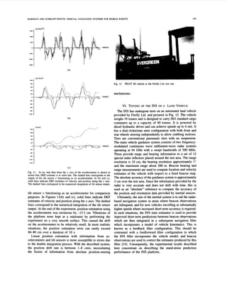
The INS system described in this paper comprises three
solid-state rate gyroscopes, a triaxial linear accelerometer
manufacturedby ENTRAN Devices Ltd., and two Electrolevel
inclinometers (or tilt sensors) by TILT Measurement Ltd., all
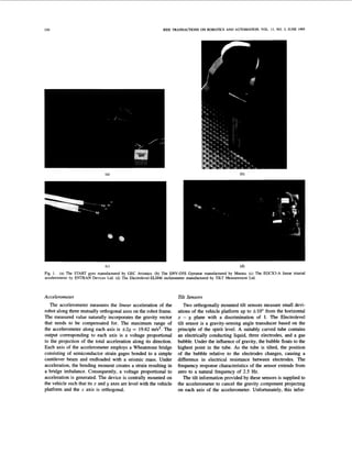
pictured in Fig. 1.
Gyroscope
Two differenttypes of gyroscopeshave been consideredand
evaluated: the Solid STate Angular Rate Transducer (START)
gyroscope manufactured by GEC Avionics and the ENV-05s
Gyrostar manufactured by Murata [9]. The START gyroscope
is an inertial sensororiginally intendedfor the guided munition
market in the 1980’s but which has also proved to be very
suitable for the vehicle control market [lo], [l11. The device
consists of a small cylinder with integral piezoelectric trans-
ducers and an integrated-circuit module [12]. The principle
of operation is to measure the Coriolis acceleration caused
by angular rotation of a vibrating cylinder, chosen for its
symmetry, around the principal axis. The cylinder is open
at one end and supported on a base at the other end. Eight
piezoelectric transducers are attached symmetrically around
the open end of the cylinder for driving, controlling and
measuringthe vibrations via the integrated circuitmodule [13].
The Gyrostar is a small relatively inexpensive piezoelectric
gyro originallydevelopedfor the automobilemarket and active
suspension systems [9]. The main application of the Gyrostar
has been in helping car navigation systems to keep track of
turns for short durations when the vehicle is out of contact
with reference points derived from the additional sensors. The
principle of operation is very similar to that of START but the
geometry is radically different: It consists of a triangular prism
made of a special substance called “Elinvar,” on each vertical
face of which a piezoelectrictransduceris placed. Excitationof
one transducer at about 8kHz, perpendicularto its face, causes
vibrations to be picked up by the other two transducers. If the
sensor remains still, or moves in a straight line, the signals
produced by the pick-up transducers are exactly equal. If the
prism is rotated around its principal axis, Coriolis forces in
proportion to the rate of rotation are created.
Both gyroscopes generate voltage outputs proportional to
the angular velocity of the vehicle around the principal axis of
the device. The maximum rate that can be measured with the
particular START gyro under investigation is f200”/s within
its linear range. The corresponding value is f90°/s for the
Gyrostar. If the input rate goes beyond the maximum limits,
the rate and orientation information become erroneous and
need to be reset.](https://image.slidesharecdn.com/inertialnavigationsystemsformobilerobots-220615044716-22ccd1d2/85/Inertial_navigation_systems_for_mobile_robots-pdf-2-320.jpg)
![BARSHAN AND DURRANT-WHYTE: INERTIAL NAVIGATION SYSTEMS FOR MOBILE ROBOTS
A A
LISA 11-C
___.__.___.________.__..__
331
IO M BlTslsFC S F R M
mation is only useful when the vehicle is stationary since tilt
sensors are inherently sensitive to acceleration as well. When
the sensor is subject to an acceleration a in a direction normal
to its measuring axis in the horizontal plane, the resultant
of this acceleration and the acceleration due to gravity g
determines the position of the bubble. If the sensor is also
tilted from the horizontal by a, the measured effective angle
is
1
aeff= a +tan-l?.
9
1
The block diagram for the hardware implementation of the
inertial sensors is shown in Fig. 2. The outputs of the inertial
sensors are multiplexed and fed to a 12-bitA/D converter. The
digitized output is interfaced to an INMOS-T805 transputer.
The total cost of this inertial package is approximatelyf 5000
which is substantially less than the typical cost of inertial
systems used in aerospace applications.
A
MOBILE ROBOT PLATFQKM
rv
111. ERROR
MODELLING
OF INERTIAL SENSORS
Constructing Error Models
Building error models for inertial sensors is motivated
by an attempt to reduce the effect of unbounded position
and orientation errors. Dependmg on how successful these
models are, inertial sensors may possibly be used in an
unaided mode or for longer durations on their own. The error
characteristics that dominate the operation of the INS depend
on the type of inertial sensors involved. The gyroscope drift
in its various manifestations is the most important contributor
to navigation system errors, and is mainly dependent upon the
devicetechnology. A detailed treatment of modeling aerospace
INS'S can be found in the first volume by Maybeck [14].
For a robotic INS, the scale, nature and parameters of the
localization problem are different than in aerospace. Hence,
INS's developed for aerospace applications cannot be directly
implemented on mobile ground vehicles. In addition, systems
developed for aerospace are far too expensive to be used in
robotics applications.
Fig. 3 illustrates the configuration of the INS package. The
accelerometer is mounted centrally on the INS plate, and the
tilt sensors are mounted along the z and y axes of the robot
frame. The location of the gyroscopes are insignificant as
long as they are orthogonal sincethe measured angular rate
is independent of the chosen coordinate frame.
To develop error models for the two types of gyroscopes,
their outputs were recorded over long periods of time when
subjected to zero input, i.e. the gyroscopes were stationary
on the laboratory bench. The result of this experiment over
a period of 12 hours is shown in Figures 4(a) and (b) for
START and Gyrostar, respectively. Ideally, the output for
zero input would be a constant voltage level corresponding
to the digital output of 2 048 for a 12-bit A/D converter as
shown by the thick, solid horizontal line in the figures. The
standard deviation of the output fluctuations is approximately
0.16'/s for the START and 0.24"/s for the Gyrostar. For
both gyroscopes, the real output data is at a lower level
TlLT SENSOR Y ,
I _ ..._..._........._..---
t
. .-..
I
!BIT
M
N E R m
I-
.
-.
.
-.
.
.
12Bm
--.
7 1
Fig. 2. Hardware implementation of the INS.
than ideal at start-up, and the mean value gradually increases
with time in an exponential fashion. Repeatability of these
results indicates that an apparently small time-varying bias is
characteristic of these gyros. The time variation of the bias is
attributed to thermal effects based on the observation that the
gyroscope units gradually heat up during operation. The bias
can taper off to a negative or positive value depending on the
ambient temperature. The results indicate that the Gyrostar
reaches its steady state much faster than the START. Drift
in the rate output of Gyrostar is about 30 mV (1.35'/s) 10
min. after switching on and, provided there is no temperature
change, about a further 10 mV (0.45'/s) during the next 24
hours [9].
The same experiment to assess the drift has also been
performed for each axis of the accelerometer and for the two
tilt sensors. The error characteristics of the accelerometeraxes
are of similar form but with differing parameters. The z axis
data has been shown in Fig. 5 as an example. The error at
the voltage output of each axis is characterized by a large
negative bias that drifts over time. For the tilt sensors, the](https://image.slidesharecdn.com/inertialnavigationsystemsformobilerobots-220615044716-22ccd1d2/85/Inertial_navigation_systems_for_mobile_robots-pdf-4-320.jpg)
![332 IEEE TRANSACTIONS ON ROBOTICS AND AUTOMATION, VOL. 11, NO. 3, JUNE 1995
INS CONFIGURATION
ACCELEROMETER
TI LTSENSOR X I
I
Fig. 3. Geometric configuration of the INS.
A/D output = 2048 ($ + 1)
t I I
ideal output
parameterfit
CI*(l -e-*) +c,,
mu , time(hours)
0 2 4 6 8 10 I2
A/D output = 2048 (9
+1)
' idealoutput
0 OeI.
' I
output does not exhibit any drift, obviating the need to build
an error model [151. The dominating source of error for the
tilt sensors is the input-output nonlinearity for angles between
A/D output = 2048 (e+1)
2sm I time(hours)
0 2 4 6 8 IO 12
Fig. 5. Digitized output of the I axis of the ENTRAN accelerometershown
along with the fitted model of form C
l
(
1-e- f ) +Cz.Data was collected
over a period of 12 hours by sampling every minute when the z axis was
subject to gravity.
f5-10'. The calibration data provided by the manufacturer
is used to model this effect.
In the following, let ~ ( t )
be the bias error associated with
measuring the true value of a quantity of interest using
inertial sensors.A nonlinearparametric model of the following
form was fitted to the data from the gyroscopes and the
accelerometer using the Levenberg-Marquardt iterative least-
squares fit method [16]:
where E model(t) is the fitted error model to the gyroscope
output when zero input was applied, with parameters CI, C2,
and T to be tuned. Starting with reasonable initial guesses for
the parameters, convergence to a local minimum is achieved
within 5-10 iterations. The best fitting parameter values to
the experimental data are tabulated in Table I for the inertial
sensors which comply with this model. Note that the z axis
of the accelerometer is subject to gravity when no other
acceleration is applied to the sensor. Since the tilt sensors
do not exhibit this type of drift error, they are not included
in the table.](https://image.slidesharecdn.com/inertialnavigationsystemsformobilerobots-220615044716-22ccd1d2/85/Inertial_navigation_systems_for_mobile_robots-pdf-5-320.jpg)
![BARSHAN AND DURRANT-WHYTE INERTIAL NAVIGATION SYSTEMS FOR MOBILE ROBOTS 333
TABLE I
DRIFT
MODEL
PARAMETERS FOR VARIOUS hXTL4L SENSORS
Testing Adequacy o
f Error Models
In general, a model fitted to experimentaldata is regarded as
being adequate if the residualsfrom the fitted model constitute
a white, zero-mean process. Hence, one can start with any
reasonable model based on inspecting the original data and
test its residuals for whiteness. If the test fails, the model can
be further developed until the residuals pass the whiteness
test. This implies that the test for the validity of any model is
basically reduced to a test for whiteness.
Following this route, the sufficiency of the above model in
(2) is determined for each sensor by applying a whiteness test
to the residuals in the autocorrelation domain. For a discrete
system with sampling interval T,, the residual w(k) at time
kT, is computed as follows:
Since the trend in the data has been subtracted out, the
process w(k) is assumed to be stationary, in which case the
autocovariance R,, becomes only a function of the lag A
between two data samples. When only a finite set of N data
samples is available for estimation, the expressions for the
sample biased autocovariance estimate is given by [17]:
(4)
1 N-lAl-l
&,(A) = -
N
w(k)w(k+A).
k=O
Ideally, the autocorrelation function of a zero-mean white
process is a spike for zero lag (A = 0), corresponding to
the process variance, and zero otherwise. With a finite and
fixed number of data points, the sample autocorrelation will
have some fluctuations around the ideal that need to be tested
for statistical significance. If N is sufficiently large (N >16),
it can be shown that [18] the distribution of the sample
autocovariance estimate for nonzero A is well approximated
by a Gaussian distribution with zero mean and standard error
given by:
1.0
0.8
0.6
0.4
0.2
0.0
Fig. 6. Biased sample autocorrelation estimate of the residuals. The result
was obtained by an ensemble average over the autocorrelationsof 10 data
sequences, each of 10 s duration. The dotted lines indicate ~e
and
f a -
M R w w (0)
f 2 B R
bounds for the autocorrelation estimate.
In Fig. 6, the sample autocorrelation estimate, i.e. sam-
ple autocovariance estimate scaled by the estimated process
variance R,,(O), is shown for the START gyroscope. An
ensemble average over the autocorrelation estimates of M =
10 data sequences (each of 10 s duration) was taken, reducing
the standard error bounds by &.The dotted lines corre-
b - 2bR
spond to the fmFw(o) and fmri~;(o) bounds for the
autocorrelationestim2;. These bounds determine the standard
error for estimating the autocorrelation of a white process,
given the finite and fixed amount of data [19]. Since the
sample autocorrelation error distribution of a white process
is Gaussian the autocorrelation estimate is bound to lie
withinfmEiww(o)95.5% of the time. In compliance, the
2AR
w w](https://image.slidesharecdn.com/inertialnavigationsystemsformobilerobots-220615044716-22ccd1d2/85/Inertial_navigation_systems_for_mobile_robots-pdf-6-320.jpg)
![~
334 IEEE TRANSACTIONS ON ROBOTICS AND AUTOMATION, VOL. 1I , NO. 3, JUNE 1995
25R
results indicate that the estimate is within f w w about
96% of the time.
The positive outcome of the whiteness test on the model
residuals demonstrates that the model in (2) adequately repre-
sents the slowly varying bias error on the rate output of the
START gyroscope. The same whiteness test has been applied
to the residuals of the model for the Gyrostar and each axis of
the accelerometer. The results have proven to be positive but
are not included here for brevity. In the next section, the error
models developed are exploited in an EKF to compensate for
the errors.
d m R W W ( O )
Implementation of the Error Models
represented by the following differential equation:
The parametrized model of (2) for the bias error can be
with initial conditions ~ ( 0 )
= C2 and i(0) = $$. After
discretization, (6) becomes
E(k +1)= -5- E(k) +-
I s (Cl+C2)
T +T, T +T,
with
E(0) = (7.2. (7)
Due to its recursive nature, this difference equation is inde-
pendent of start-up time but relies on a good estimate of the
initial bias.
The quantities observed by the INS incorporate the bias
errors described by (7). The observations are the rate outputs
of the gyros, acceleration components on the robot frame and
the two tilt measurements,leading to the nonlinearobservation
equations shown at the bottom of this page. Here, a,, ay and g
are the accelerationsof the robot in the world coordinateframe,
related to the measured accelerations by a rotational transfor-
mation through the Euler angles [20]0,4,'P around z, y and z
axes, respectively. The observations ZG, (k),ZG, (k),ZG,(k),
Z A , ( ~ ) , ZA,(~) and z ~ , ( k ) ,
are, respectively, of the Euler
angle rates j ( k ) , q(k), &(k), and the accelerations u,(k),
uy(k), aZ(k)along the z, y, and z axes. Each observation
is taken in additive drift ~ e ( k ) ,
~ $ ( k ) ,
€&(IC), ~ ~ ~ ( k ) ,
caV(k),
eg(k),each independently modeled by (7), and additive white
noise wl(k), w2(k), w3(k), wq(k), 215(k), wg(k), respectively.
Note that the tilt sensor outputs are not directly supplied as
observations to the filter. Since the tilt sensors provide more
accurate angular information than the gyroscopes when the
robot is not accelerating, the gyros are reset by the outputs of
these sensors whenever the absolute value of all the accelera-
tion componentsare less than a prefixed threshold whose value
is determined by the noise level of the accelerometer output.
The tilt sensors do not directly measure the Euler angles but
the inclinationwith respect to the horizontal plane, whereasthe
integrated output of the gyroscopes correspond to the actual
rotations around each axis on the robot frame. Suppose CY, and
ayare the angles with the horizontal plane measuredby the tilt
sensors lying along z and y axes, respectively. From simple
geometry, these are related to the Euler angles as follows:
8 = CY,
q = Qy,
cosa,
Equations (7) can be rewritten in matrix notation as
z ( k ) = h[x(k)]
+v(k) (11)
where x(k)is the state vector as described below and v(k)is
a white measurement noise process vector.
Given the observations, the states that need to be estimated
are the true values of orientation, angular rate, linear accelera-
tion, velocity, position and the errors associated with them.
Hence, the states of interest are augmented by (7) for the
sensors involved, to estimate and compensate for the time-
varying bias errors. The resulting state equations of the EKF
k)laz(k)
+[sin0(k).sin $(IC). sin @(k)+cos 0(k).cos@(k)]a,
(k)
+sinO(k).cos$(k).g(k) +ca,(k) +w5(k)
= [cose(k).sin $(k ) .cos 'P(k ) +sin 0(k).sin 'P(k)]a,(k)
+[cos0(k).sin $(IC). sin 'P(k) - sin e(k).cosa(k)]ay( k )
2.4, (IC)
+cos8(k).cos$(k).g(k)+cg(k) +vf.j(k).](https://image.slidesharecdn.com/inertialnavigationsystemsformobilerobots-220615044716-22ccd1d2/85/Inertial_navigation_systems_for_mobile_robots-pdf-7-320.jpg)
![BARSHAN AND DURRANT-WHYTE INERTIAL NAVIGATION SYSTEMS FOR MOBILE ROBOTS
X G , (IC +1)-
XG, (k+1)
XGZ(ICf l)
XA, (IC +1)
XA, (k+1)
-xA, (IC +1)-
=
LUA, J
-FG= 0 0 0 0 0
O F G , O 0 0 0
0 O F G , O 0 0
0 0 O F A , O 0
0 0 0 O F A , O
- 0 0 0 0 0 FA,
with
O T .
-20
-40
-60
-80
and
-
- '
7
, 1
- :
'
k
-
.
" " " " '
-
335
0
.
5
0.0
-
0
.
5
The remainingblock matrices FG,,FG,,FA,, FA^, and block
state vectors XG,, XG,, XA,, XA, in (12) have very similar
definitionsto those in (13) and (14) but with the corresponding
error model parameters substituted in. The overall state vector
comprises 30 states. More compactly, (12) can be rewritten as
(13)
Note that the state transition is linear unlike the nonlinear
measurements described by (11). The first four states are the
true values of the orientation and its derivatives, and the next
two states constitute the error model for the gyroscope. This
part of the filter has a constant (a (k)structure augmented by
the error model. Lower-order filters have been implemented
but shown to have a delay and much ringing in their unit-
step response. With this higher-order model, the filter is able
to track abrupt changes in angular velocity very closely as
will be shown in the next section. The remaining states of
the filter correspond to the true values of position, velocity
and acceleration in the world frame, plus the error states for
measuring acceleration. One interesting point to note is that
for each different sensor, the error states are coupled to their
relevant true states only through the observationequations and
not by the structure of the state transition matrix F.
In setting the process noise covariance matrix Q for the
EKF, a continuous-time white-noise model is assumed as
described in [21]. With this assumption for each independent
sensor block, the following process noise covariance matrix
(14)](https://image.slidesharecdn.com/inertialnavigationsystemsformobilerobots-220615044716-22ccd1d2/85/Inertial_navigation_systems_for_mobile_robots-pdf-8-320.jpg)
![20
0
-20
-40'0 1 2 3 4 5
time(min)
(a)
-40' I
0 1 2 3 4 5
time(min)
IEEE TRANSACTIONS ON ROBOTICS AND AUTOMATION, VOL. 11, NO. 3, JUNE 1995
500
0
-500
-1000
0 1 2 3 4 5
-1500
time(min)
(b)
W e d
0
-20
-40
-60
-80
-100
0 1 2 3 4 5
time(min)
(d)
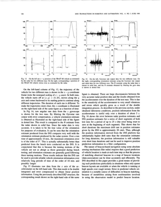
Fig. 8. (a) Angular rate; and (h) position of the START gyroscope when nonzero input is applied. A new angular rate was randomly generated every
30 s and applied to the gyro. The true values (thin, solid lines) and the erroneous Observations (dotted lines) are displayed along with the EKF results
(thick, solid lines) which compensate for the error. (c) Error in the angular rate and (d) error in orientation. Both the true (thin, solid lines) and the
estimated values (heavy, solid lines) are shown.
can be derived:
0 0 0 0
[YQG 0 0 0 X 1
with
l o 0 0
and
where u
1 = 0.05"/s3,u2 = 0.2"/s, u3 = 3 cm/s2, and 0 4 =
0.01 cm/s2, with u2,u4 being the experimentally determined
standard deviations of the residuals from the fitted models.
The state vector estimated by the filter is given by the
standard recursive estimator
x ( k +Ilk +1)= FX(k(k)+ U +W(k +l)v(k+1) (18)
where x(k +llk+1)is the estimate made of the state vector
at time (k + l)Ts based on all observations up to this time,
x(klk) is the estimate at the previous time-step, W(k + 1)
is the filter gain, and v(k +1) = z(k + 1)- h[x(k+ilk)]
is the innovations vector provided by the new observations at
time ( k + l)T,. A detailed treatment of EKF prediction and
update equations can be found in [21]. An important point to
note is that all states, including drift parameters, are estimated
at every sample time.
The EKF structure in (11) and (16) has been implemented
in real time on an INh4OS-T805 transputer network where a
minimum sampling interval of T, = 30 ms is achieved. Each
gyroscope has been mounted on a rotating platform whose
angular velocity and orientation can be accurately controlled
and measured. An HCTL-1100 chip was used to control the
motor in the integral velocity mode. The motor position from
the encoder is accurate to 1/2000 of a revolution. A 500-line
optical encoder was used to measure motor position, driving](https://image.slidesharecdn.com/inertialnavigationsystemsformobilerobots-220615044716-22ccd1d2/85/Inertial_navigation_systems_for_mobile_robots-pdf-9-320.jpg)