Artificial intelligence in the post-deep learning era
Inertia dynamics torque_arm_acc_specsheet
1. E-12
E
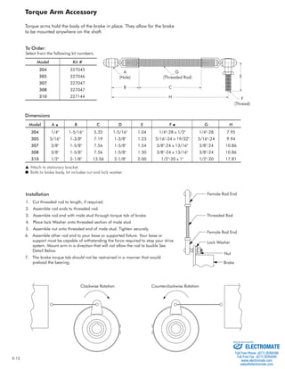
Torque Arm Accessory
Torque arms hold the body of the brake in place. They allow for the brake
to be mounted anywhere on the shaft.
H
A
(Hole)
B
G
(Threaded Rod)
F
(Thread)
C
To Order:
Select from the following kit numbers.
Model Kit #
304 327045
305 327046
307 327047
308 327047
310 327144
Dimensions
Model A ▲ B C D E F ● G H
304 1/4" 1-5/16" 5.33 1-5/16" 1.04 1/4"-28 x 1/2" 1/4"-28 7.95
305 5/16" 1-3/8" 7.19 1-3/8" 1.23 5/16"-24 x 19/32" 5/16"-24 9.94
307 3/8" 1-5/8" 7.56 1-5/8" 1.54 3/8"-24 x 13/16" 3/8"-24 10.86
308 3/8" 1-5/8" 7.56 1-5/8" 1.50 3/8"-24 x 13/16" 3/8"-24 10.86
310 1/2" 2-1/8" 13.56 2-1/8" 2.00 1/2"-20 x 1" 1/2"-20 17.81
▲ Attach to stationary bracket.
● Bolts to brake body, kit includes nut and lock washer.
Installation
1. Cut threaded rod to length, if required.
2. Assemble rod ends to threaded rod.
3. Assemble rod end with male stud through torque tab of brake.
4. Place lock Washer onto threaded section of male stud.
5. Assemble nut onto threaded end of male stud. Tighten securely.
6. Assemble other rod end to your base or supported fi xture. Your base or
support must be capable of withstanding the force required to stop your drive
system. Mount arm in a direction that will not allow the rod to buckle See
Detail Below.
7. The brake torque tab should not be restrained in a manner that would
preload the bearing.
Female Rod End
Threaded Rod
Female Rod End
Lock Washer
Nut
Brake
Clockwise Rotation Counterclockwise Rotation
Sold & Serviced By:
ELECTROMATE
Toll Free Phone (877) SERVO98
Toll Free Fax (877) SERV099
www.electromate.com
sales@electromate.com