Download to read offline

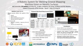
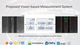
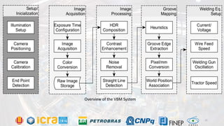
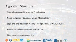

1) The document describes a robotic vision system for mapping welding grooves on metallic surfaces using machine vision techniques without complex optical setups. 2) A prototype system was developed using an FPGA, camera, and welding robot to autonomously map groove dimensions in real-time to improve welding quality over manual processes. 3) Experimental results found the Gaussian filtering and line segment detection approach achieved sub-millimeter accuracy and repeatability in measuring groove widths, outperforming other filtering and edge detection algorithms tested. Further improvements to lighting and image processing are ongoing.


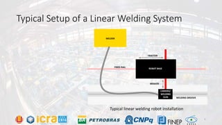
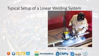
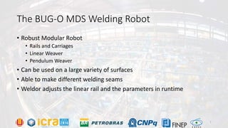
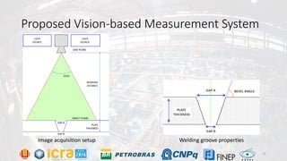
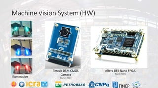
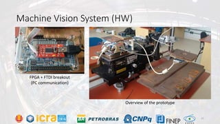
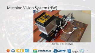
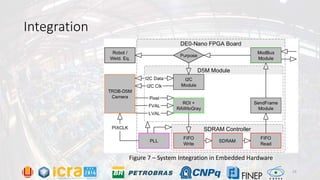
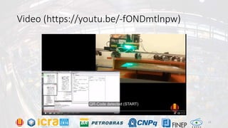
![Polymer [ बहुलक ] Chemistry Notes PDF - Irfanullah Mehar - JJ Sir Chemistry.pdf](https://cdn.slidesharecdn.com/ss_thumbnails/polymerchemistrynotespdf-irfanullahmehar-jjsirchemistry-260210172118-3f9b37f7-thumbnail.jpg?width=640&height=640&fit=bounds)


