Download to read offline

![www.htr-india.com
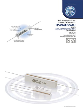
WIRE WOUND
RESISTORS
CERAMIC
ENCASED TYPE
ELECTRICAL & ENVIRONMENTAL CHARACTERISTICS / DATA
PARAMETER / PERFORMANCE TEST & TEST METHOD
PERFORMANCE REQUIREMENTS
Power Rating (Rated Ambient Temperature)
Full Power dissipation at 70°C and linearly
derated to zero at 350°C (Refer Derating curve above)
Resistance Tolerances Available
±10% (K); ±5% (J); ±3% (H); ±2% (G); ±1% (F)
Temperature Range
-55°C to +350°C with suitable derating as per derating curve
Voltage Rating / Limiting Voltage / Max Working Voltage
V= PxR
Maximum Overload Voltage
Varies depending on resistance value, duration of overload and
type of pulse waveform (contact factory for details)
Voltage Proof / Dielectric Withstanding Voltage
(based on limiting voltage x 2 for 60 secs)
∆R ± [1% + R05] - No flashover, mechanical
damage, arcing or insulation breakdown
Short Time Overload (5 x Rated Power for 5 secs)
∆R ± [2% + R05]
Temperature Co-efficient of Resistance
±120 ppm/°C for <R10 (Average)
±80 ppm/°C for <1R0 (Average)
±60 ppm/°C for <100R (Average)
±90 ppm/°C or ±30 ppm/°C for >100R
depending on wire selected
Insulation Resistance
>1000MΩ (Min)
Temperature Cycling
(Room Temperature -55°C Room Temperature
200°C Room Temperature for 5 cycles)
∆R ± [2% + R05]
Damp Heat (Steady State)
(40°C at 93% R.H for 1000 hours - no load applied)
∆R ± [2% + R05] - Average
Endurance - Load life
(70°C with limiting voltage - 1.5 hours on /
0.5 hours off for 1000 hours)
∆R ± [≤3% + R05] - Average
HSVA/
HSVAU
MECHANICAL SPECIFICATIONS
PARAMETER / PERFORMANCE TEST & TEST METHOD
PERFORMANCE REQUIREMENTS
Terminal Tensile Strength
50 Newtons
Resistance to Soldering Heat (260°C - 270°C for 10 secs)
∆R ± [0.2% + R05] - Typical
Solderability (As per IEC - 60068 - 2 - 20Ta)
Must meet the requirements laid down
Marking
As per IEC Pub. 60062
TYPICAL APPLICATIONS
The HSVA series enjoys a wide market in TV, power supply and industrial electronics field. Depending upon the resistance value and
application, the resistor core may be fibreglass or ceramic.
These resistors are also available for use in pulse applications. For further information, please refer to “Pulse / Surge capability of resistors”.
In case a tailor-made pulse resistor is required, please refer to “Questionnaire of data required from customers” and provide data accordingly.
The HSVAU series are very popular with stockists as they are capable of dual mounting - axial or vertical hence are instrumental in
reducing inventory.
Note:
1. Due to recent technological advances, the ceramic cases used may be steatite ceramic or corderite ceramic or high alumina ceramic
depending on the nature of the application. Hence the ceramic cases may be off-white or variations of brown and variations of grey;
colours which are inherent to these ceramic materials.
2. In case the device will be subjected to aggressive solvents, please inform factory so case filling can be changed to solvent resistant type.
ORDERING INFORMATION
Series
HSVA/ HSVAU
HTR type
Packing
Resistance Value
SV9A / SV9A*
SV9AU / SV9AU*
Bulk SV9A / SV9A*
SV9AU / SV9AU*
100R
Tolerance
J
1. For RoHS version - SV9A * / SV9AU *
2. For Non Inductive type - N SV9A / N SV9AU
3. For Pulse type - SV9A I / SV9AU I
e : info@htr-india.com](https://image.slidesharecdn.com/hsva-hsvau-140131074615-phpapp01/85/HTR-India-Products-Wire-Wound-Resistors-Ceramic-Encased-Resistor-HSVA-HSVAU-English-3-320.jpg)

The document details the specifications and features of the HSVA/HSVAU series wire wound resistors, which are available in ceramic encased types for axial and vertical mounting. These resistors have a power rating between 4W to 17W, a resistance range of R04 to 82K, and offer various electrical and environmental characteristics such as temperature range and resistance tolerances. They are commonly used in TV, power supply, and industrial electronics applications, and are popular among stockists for their dual mounting capability.


