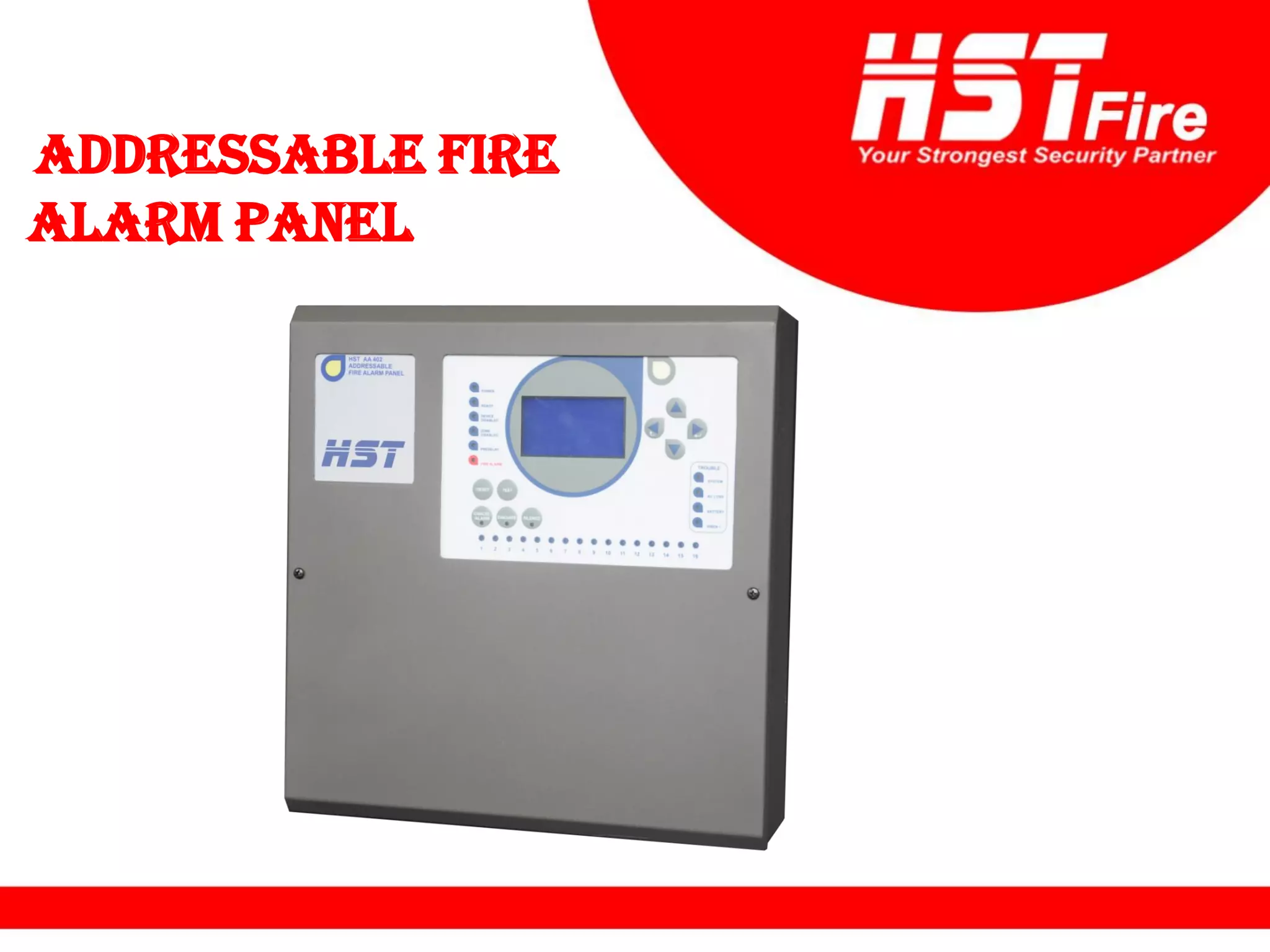
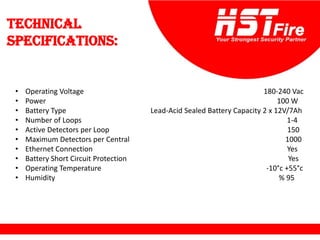
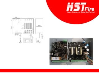
ADDRESSABLE FIRE
ALARM PANEL
Technical
specifications:
• Operating Voltage 180-240 Vac
• Power 100 W
• Battery Type Lead-Acid Sealed Battery Capacity 2 x 12V/7Ah
• Number of Loops 1-4
• Active Detectors per Loop 150
• Maximum Detectors per Central 1000
• Ethernet Connection Yes
• Battery Short Circuit Protection Yes
• Operating Temperature -10°c +55°c
• Humidity % 95
• Siren Output:
• Output Type Normally Open
• Contact Rate 1 A @ 30 Vdc
• Fuse 400 mA Automatic Reset
• Maximum Voltage 32V
• End of Line Resistor 4K7 KOhm
• Open Collector Outputs (1,2,3):
• Output Type Open Collector
• Output Current 50 mA max
• Maximum Voltage 32V
• Alarm Relay Output:
• Output Type Normally Open (NO), Normally Closed (NC)
• Contact Rate 1 A @ 30 Vdc
• Error Relay Output:
• Output Type Normally Open (NO), Normally Closed (NC)
• Contact Rate 1 A @ 30 Vdc
• 24V Output Yes 400mA max
• Loop Power 300mA maximum
• Loop Load 120R
• Serial Out (RS-485):
• Baud Rate 19200
• Data bits 8
• Parity None
• Stop Bit 1
• Flow Control None
• Case Material Metal Case 1.2mm
• Environmental Category IP30
• Dimensions 34,5 x 36 x10,5 cm
• Weight 1.8 kg
• Data retention 10 years
Basic Fire
Main Controller
• The brains of the system.
• Provides power to the system, monitors inputs and controls outputs through various
circuits.
• Performs other functions as required by the appropriate code
Elements of
a Control Panel
Requires two Power Sources :
• AC power source.
• Battery 12V/7AH (2)
Primary (AC)
Secondary (DC 24V)
Elements of
a Control Panel
Inputs:
• A fire alarm system can have a variety of input devices
Detector
Manual call
point
Elements of
a Control Panel
Outputs:
• A fire alarm system can have a variety of input devices
sounder Bell
Types of Fire Alarm
Control Panels
Addressable panel:
- 4 loops
Battery connection
2Battery
DC, 12 V / 7Ah
4 (+v) terminal
3 (-v) terminal
Connections:
Each bell 18mA
Power led
Ready/Fault led
Disabled led
Zone disabled led
Predelay led UP button
Enter
Down
Escape
Zone leds
Trouble indicators
System fault
indicator
AC loss indicator
Battery indicator
Siren indicator
Reset button
Cancel alarm
button
Test button
Evacuate
button
Silence
button
Access levels
There are 4 access levels:
Level 1: Untrained User.
Level 2: Authorized User.
Level 3: Service and Maintenance Engineer.
Level 4: Factory Setup and Senior Service
Engineers.
Lamp test, Silence buzzer, Menu navigation
Acknowledge alarms and reset the system, enable the panel controls.
It is possible to read or interrogate the site specific data on the panel,
The installer can do all facilities and programming in the Menu.
Only manufacturer or authorized technical person of distributor can
intervene to the panel, Return to factory defaults, Program memory can be
changed
Menu
Press Enter
1-The Maın Menu items are as
follows:
When entered in Zones Menu :
:
Zones
-
1
Zone number Number of devices
A)To change Zone name :
B)To change Predelay:
C)Change between enabled or
disabled by UP & Down and
save by pressing escape:
D)Multiple trigger :
In case of an alarm from the devices defined in
the zone, the system waits for another device
defined in the same zone to be alarmed in
order to be alarmed.
E) Outputs are used to get zones to do various
jobs with different delays.
Output1:
This output group contains 250 output
channels. Each channel means a job to be
done.
it is possible to perform different operations as
follows.
- Relay On
- Relay Off
- Switch Relay Position
- Periodic Relay On/Off
- Periodic Relay Off/On
Output delay between 1 and 250 seconds can
be defined for this output. This output group
can only activate the relays on the panel where
it is set.
Output2:
Output delay between 1 and 250 seconds can
be defined for this output.
In networked extended systems, the Output 2
Group effects directly. In case of an alarm
coming from any panel in the network, the
output units on any of the other panels in the
network can be activated.
Output delay cannot be defined for this
output. The exit delay defined for the zone is
also valid for this group.
Output3:
In networked extended systems, the Output 3
Group effects directly.
Loops:
-
2
When enter key is pressed:
• Loop xx Enabled: Loop can be disabled and
reactivated from this menu.
• All Loop Leds On: It turns on the alarm leds
of all devices connected in the relevant loop
continuously.
• Cancel All Tests: Ends all tests started in the
loop.
• Walk test mode: After this mode is
activated, the panel monitors all devices in
order of address.
• Walk Period: The duration of each
device being active in the walk test.
Selecting Auto-Search will initiate a search
over the loop.
Automatic search does not start in case of loop
errors or it does not end successfully.
If “All Devices” is selected, the list of the
detectors sorted by the addresses, and the
types of the detectors , followed by status text
The abnormal status Codes are :
M : Missing
D : Disabled
O : Open
S : Short
P : Prealarm
A : Alarm
Possible device types are:
type 1 HRD Heat Detector
type 2 ION Ionized Smoke Detector
type 3 OSD Optical Smoke Detector
type 4 COM Combined Detector
type 5 BEA Beam Detector
type 6 MCP Manual Call Point
type 7 SIM Single Input Module
type 8 SOM Single Output Module
type 9 GAS Gas Detector
Devices:
In the All devices menu, move the cursor over
a desired device and press enter twice.
Set test mode on/off is using for lit of the
device leds always.
In order to test the relay contacts of SOM (output
module) devices, the "toggle output off/on" line in
the detail menu of the device is reached and
pressed once.
Change Device Text allows to show and change
the name of the device.
If the device is an output unit, output channel
is the menu that displays the output channels
and enables them to be changed.
The task of forwarding the alarm information
from the zone to the output units will be done
from output channel menu.
When the evacuate trig is select as “ON” the
device will trig by evacuate if the device is an
output unit (SOM).
Diagnose is including engineering parameter of
device.
Disabled:
-
3
If any of the zones is disabled, all outputs set in
that zone are disabled. Data exchange of all
devices in that area is interrupted.
:
Faults
-
4
Possible loop faults are short circuit, open
circuit or the loop card cannot be exist.
When the circuit is short-circuited, the panel
will display as an open-circuit fault.
The communication of the network cards with the panel is checked. When there is a
break or short-circuit, it is displayed on the panel. In this case, the connection
between the panel and the network card is checked.
If the communication between the network
cards is broken, the panel will give this error.
Event log:
-
5
The total number of events that can be kept is
limited to 65536.
there are a total of 4312 records and the
record shown is record number 4312. The
record number 4312 took place on 08.07.2021
at 15:27:00, this signal is open-circuit restored.
The data can be read and printed through the
software.
Setting:
-
6
When the access level is 2 and 3, the
system settings menu will be
accessible.
In order for the activation process to be carried
out, the manufacturer must be contacted.
In day mode, alarm delays defined in the
system are used. In night mode, alarm signals
are processed without delay, ignoring delays.
This menu will be used by the installer and can
only be used when AL4 is active.
Outputs:
-
7
The control of the relays and loop-powered
sirens on the panel is done from the output
control menu.
System Info:
-
7
This information can be changed via computer
with configuration software.
Software
To add new customer click on , Enter the
name then click on
1 2
To add the panel click on , Choose the
model no., panel type and active then click .
1 2
Click on Work Offline.
Change whatever you need.
Click connect then upload.
HST New Fire Alarm System

HST New Fire Alarm System

  • 1.
  • 2.
    Technical specifications: • Operating Voltage180-240 Vac • Power 100 W • Battery Type Lead-Acid Sealed Battery Capacity 2 x 12V/7Ah • Number of Loops 1-4 • Active Detectors per Loop 150 • Maximum Detectors per Central 1000 • Ethernet Connection Yes • Battery Short Circuit Protection Yes • Operating Temperature -10°c +55°c • Humidity % 95
  • 3.
    • Siren Output: •Output Type Normally Open • Contact Rate 1 A @ 30 Vdc • Fuse 400 mA Automatic Reset • Maximum Voltage 32V • End of Line Resistor 4K7 KOhm
  • 4.
    • Open CollectorOutputs (1,2,3): • Output Type Open Collector • Output Current 50 mA max • Maximum Voltage 32V • Alarm Relay Output: • Output Type Normally Open (NO), Normally Closed (NC) • Contact Rate 1 A @ 30 Vdc • Error Relay Output: • Output Type Normally Open (NO), Normally Closed (NC) • Contact Rate 1 A @ 30 Vdc • 24V Output Yes 400mA max • Loop Power 300mA maximum • Loop Load 120R
  • 5.
    • Serial Out(RS-485): • Baud Rate 19200 • Data bits 8 • Parity None • Stop Bit 1 • Flow Control None • Case Material Metal Case 1.2mm • Environmental Category IP30 • Dimensions 34,5 x 36 x10,5 cm • Weight 1.8 kg • Data retention 10 years
  • 6.
    Basic Fire Main Controller •The brains of the system. • Provides power to the system, monitors inputs and controls outputs through various circuits. • Performs other functions as required by the appropriate code
  • 7.
    Elements of a ControlPanel Requires two Power Sources : • AC power source. • Battery 12V/7AH (2) Primary (AC) Secondary (DC 24V)
  • 8.
    Elements of a ControlPanel Inputs: • A fire alarm system can have a variety of input devices Detector Manual call point
  • 9.
    Elements of a ControlPanel Outputs: • A fire alarm system can have a variety of input devices sounder Bell
  • 10.
    Types of FireAlarm Control Panels Addressable panel: - 4 loops
  • 11.
  • 13.
    4 (+v) terminal 3(-v) terminal
  • 15.
  • 16.
  • 17.
    Power led Ready/Fault led Disabledled Zone disabled led Predelay led UP button Enter Down Escape Zone leds
  • 18.
    Trouble indicators System fault indicator ACloss indicator Battery indicator Siren indicator Reset button Cancel alarm button Test button Evacuate button Silence button
  • 19.
    Access levels There are4 access levels: Level 1: Untrained User. Level 2: Authorized User. Level 3: Service and Maintenance Engineer. Level 4: Factory Setup and Senior Service Engineers. Lamp test, Silence buzzer, Menu navigation Acknowledge alarms and reset the system, enable the panel controls. It is possible to read or interrogate the site specific data on the panel, The installer can do all facilities and programming in the Menu. Only manufacturer or authorized technical person of distributor can intervene to the panel, Return to factory defaults, Program memory can be changed
  • 20.
    Menu Press Enter 1-The MaınMenu items are as follows: When entered in Zones Menu : : Zones - 1 Zone number Number of devices
  • 21.
    A)To change Zonename : B)To change Predelay:
  • 22.
    C)Change between enabledor disabled by UP & Down and save by pressing escape: D)Multiple trigger : In case of an alarm from the devices defined in the zone, the system waits for another device defined in the same zone to be alarmed in order to be alarmed.
  • 23.
    E) Outputs areused to get zones to do various jobs with different delays.
  • 24.
    Output1: This output groupcontains 250 output channels. Each channel means a job to be done. it is possible to perform different operations as follows. - Relay On - Relay Off - Switch Relay Position - Periodic Relay On/Off - Periodic Relay Off/On Output delay between 1 and 250 seconds can be defined for this output. This output group can only activate the relays on the panel where it is set.
  • 25.
    Output2: Output delay between1 and 250 seconds can be defined for this output. In networked extended systems, the Output 2 Group effects directly. In case of an alarm coming from any panel in the network, the output units on any of the other panels in the network can be activated.
  • 26.
    Output delay cannotbe defined for this output. The exit delay defined for the zone is also valid for this group. Output3: In networked extended systems, the Output 3 Group effects directly.
  • 27.
  • 28.
    • Loop xxEnabled: Loop can be disabled and reactivated from this menu. • All Loop Leds On: It turns on the alarm leds of all devices connected in the relevant loop continuously. • Cancel All Tests: Ends all tests started in the loop. • Walk test mode: After this mode is activated, the panel monitors all devices in order of address. • Walk Period: The duration of each device being active in the walk test.
  • 29.
    Selecting Auto-Search willinitiate a search over the loop. Automatic search does not start in case of loop errors or it does not end successfully.
  • 30.
    If “All Devices”is selected, the list of the detectors sorted by the addresses, and the types of the detectors , followed by status text The abnormal status Codes are : M : Missing D : Disabled O : Open S : Short P : Prealarm A : Alarm
  • 31.
    Possible device typesare: type 1 HRD Heat Detector type 2 ION Ionized Smoke Detector type 3 OSD Optical Smoke Detector type 4 COM Combined Detector type 5 BEA Beam Detector type 6 MCP Manual Call Point type 7 SIM Single Input Module type 8 SOM Single Output Module type 9 GAS Gas Detector
  • 32.
    Devices: In the Alldevices menu, move the cursor over a desired device and press enter twice. Set test mode on/off is using for lit of the device leds always. In order to test the relay contacts of SOM (output module) devices, the "toggle output off/on" line in the detail menu of the device is reached and pressed once.
  • 33.
    Change Device Textallows to show and change the name of the device. If the device is an output unit, output channel is the menu that displays the output channels and enables them to be changed. The task of forwarding the alarm information from the zone to the output units will be done from output channel menu.
  • 34.
    When the evacuatetrig is select as “ON” the device will trig by evacuate if the device is an output unit (SOM). Diagnose is including engineering parameter of device.
  • 35.
    Disabled: - 3 If any ofthe zones is disabled, all outputs set in that zone are disabled. Data exchange of all devices in that area is interrupted.
  • 36.
  • 37.
    Possible loop faultsare short circuit, open circuit or the loop card cannot be exist. When the circuit is short-circuited, the panel will display as an open-circuit fault.
  • 38.
    The communication ofthe network cards with the panel is checked. When there is a break or short-circuit, it is displayed on the panel. In this case, the connection between the panel and the network card is checked. If the communication between the network cards is broken, the panel will give this error.
  • 39.
    Event log: - 5 The totalnumber of events that can be kept is limited to 65536. there are a total of 4312 records and the record shown is record number 4312. The record number 4312 took place on 08.07.2021 at 15:27:00, this signal is open-circuit restored. The data can be read and printed through the software.
  • 40.
    Setting: - 6 When the accesslevel is 2 and 3, the system settings menu will be accessible.
  • 41.
    In order forthe activation process to be carried out, the manufacturer must be contacted.
  • 42.
    In day mode,alarm delays defined in the system are used. In night mode, alarm signals are processed without delay, ignoring delays.
  • 43.
    This menu willbe used by the installer and can only be used when AL4 is active.
  • 44.
    Outputs: - 7 The control ofthe relays and loop-powered sirens on the panel is done from the output control menu.
  • 45.
    System Info: - 7 This informationcan be changed via computer with configuration software.
  • 46.
  • 47.
    To add newcustomer click on , Enter the name then click on 1 2
  • 48.
    To add thepanel click on , Choose the model no., panel type and active then click . 1 2
  • 49.
    Click on WorkOffline.
  • 50.
  • 51.