Downloaded 11 times

![Configuration
38 UDC2500 Universal Digital Controller Product Manual 8/05
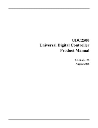
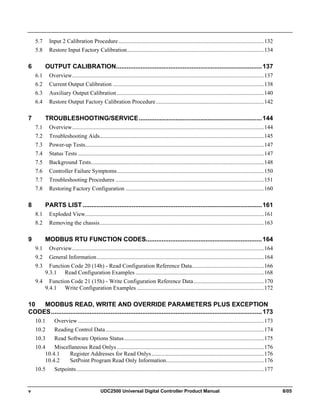
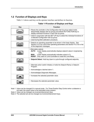
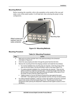
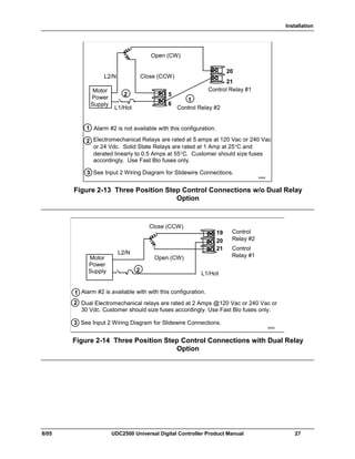
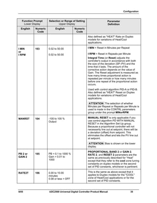
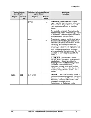
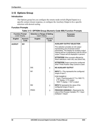
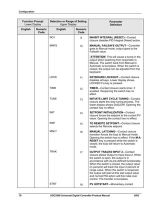
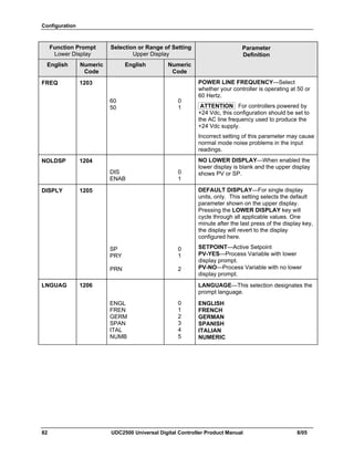
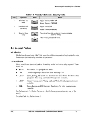
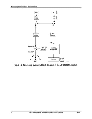
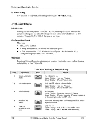
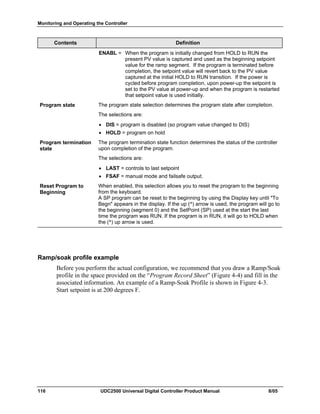
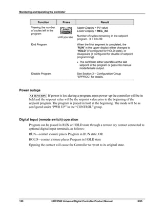
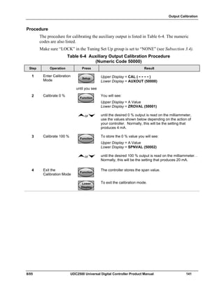
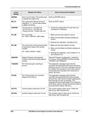
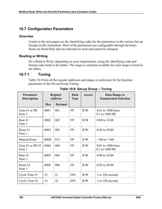
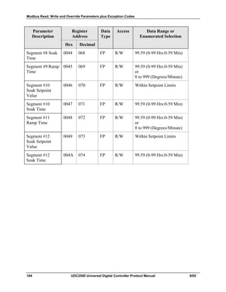
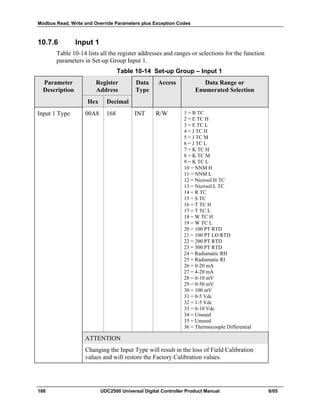
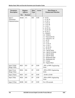
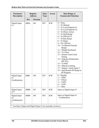
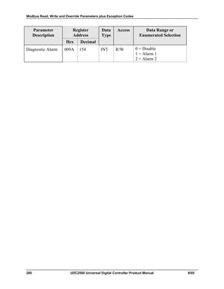
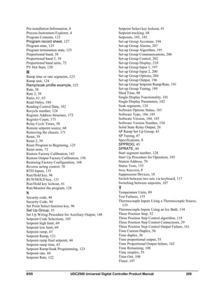
3.5 SP Ramp Set Up Group
Introduction
Set Point Ramp, Set Point Programs and Set Point Rates can be configured in this group.
A single Setpoint Ramp [SP RAMP] can be configured to occur between the current local
setpoint and a final local setpoint over a time interval of from 1 to 255 minutes.
A Set Point Rate [SPRATE] lets you configure a specific rate of change for any local
setpoint change.
A single Set Point Program [SP PROG] with up to 12 segments can be configured.
For more information on Set Point Rate, Ramp and Programming, see Sections 4.18
through 4.21.
You can start and stop the ramp/program using the RUN/HOLD key.
PV Hot Start is a configurable feature and means that, at initialization, the setpoint is set
to the current PV value and the Ramp or Rate or Program then starts from this value.
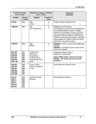
Function Prompts
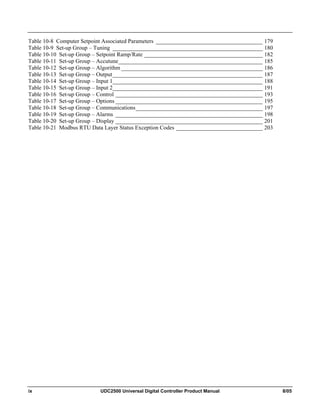
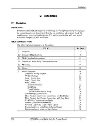
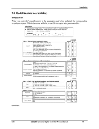
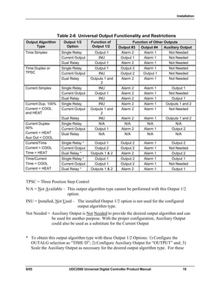
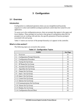
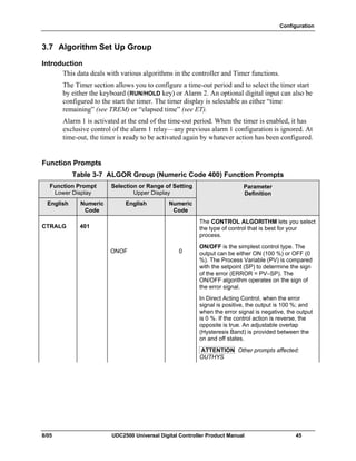
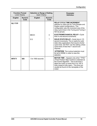
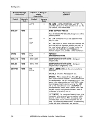
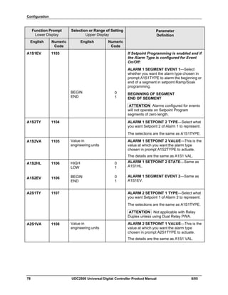
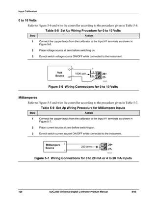
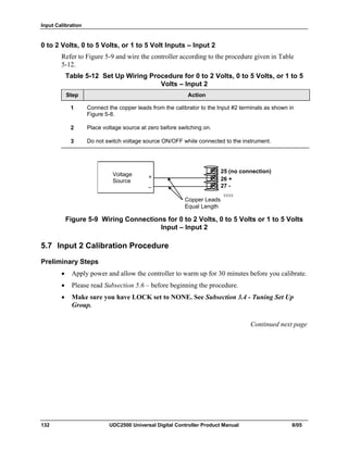
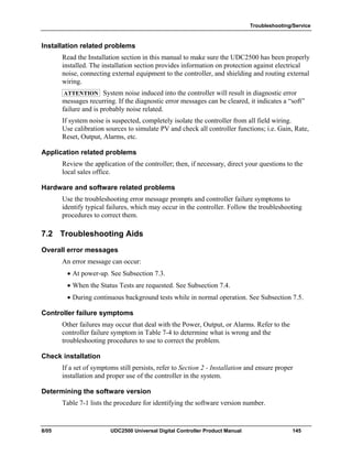
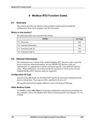
Table 3-5 SPRAMP Group (Numeric Code 200) Function Prompts
Function Prompt
Lower Display
Selection or Range of Setting
Upper Display
English Numeri
c Code
English Numeric
Code
Parameter
Definition
SP RAMP
SP Program
must be
disabled for
SP Ramp
prompts to
appear
201 DIS
ENAB
0
1
SINGLE SETPOINT RAMP—Make a
selection to enable or disable the setpoint
ramp function. Make sure you configure a
ramp time and a final setpoint value.
SP Programming must be disabled.
DISABLE SETPOINT RAMP—Disables the
setpoint ramp option.
ENABLE SETPOINT RAMP—Allows the
single setpoint ramp prompts to be shown.
TI MIN 202 0 to 255 minutes SETPOINT RAMP TIME—Enter the number
of minutes desired to reach the final setpoint.
A ramp time of “0” implies an immediate
change of setpoint.](https://image.slidesharecdn.com/honeywelludc2500-130826022228-phpapp02/85/Honeywell-udc-2500-48-320.jpg)
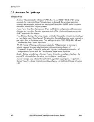

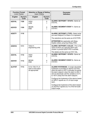

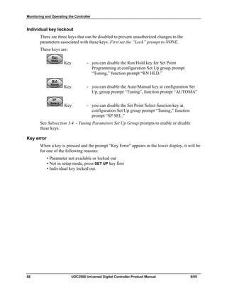
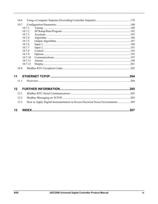
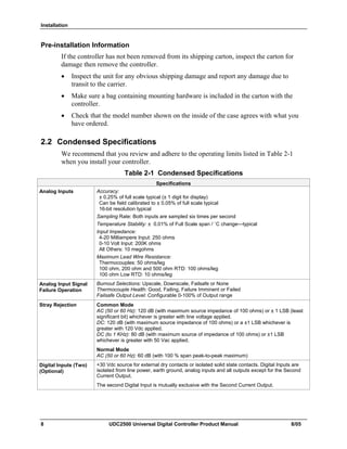
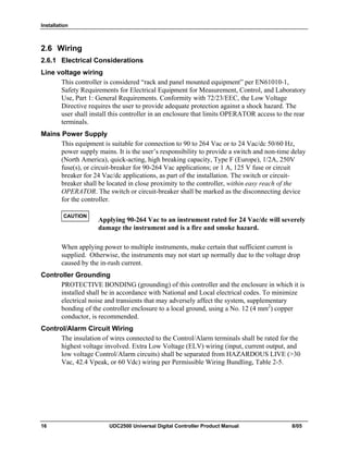
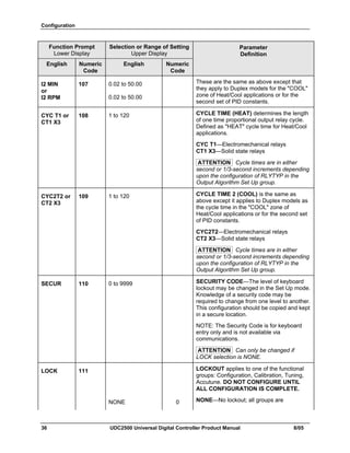
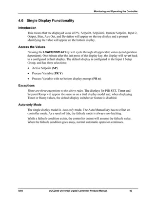
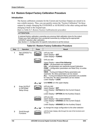
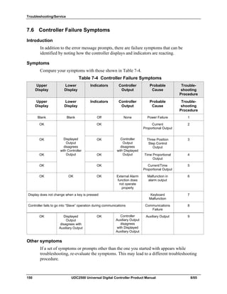
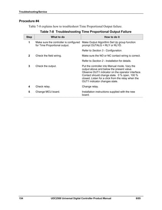
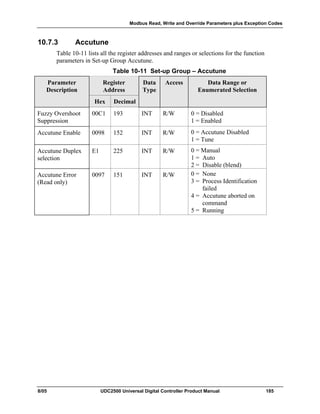
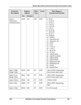
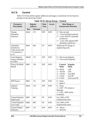
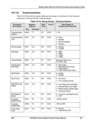
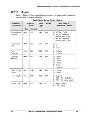
![Monitoring and Operating the Controller
8/05 UDC2500 Universal Digital Controller Product Manual 89
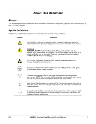
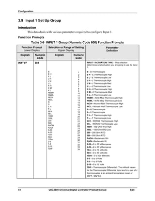
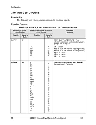
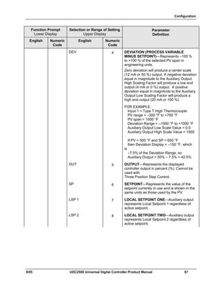
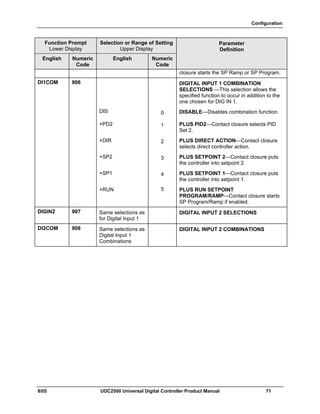
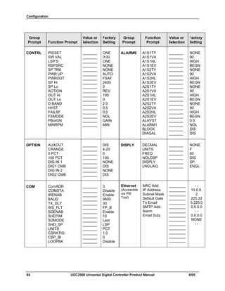
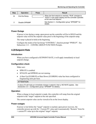
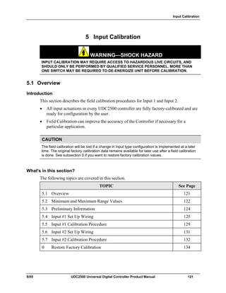
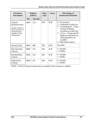
4.5 Monitoring Your Controller
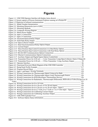
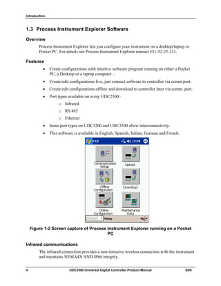
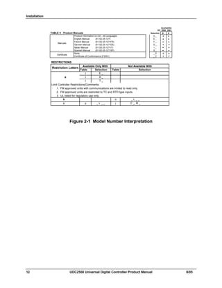
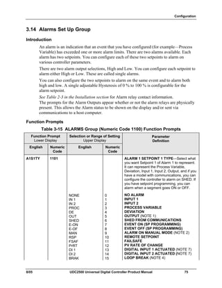
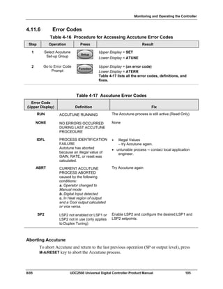
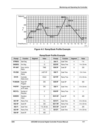
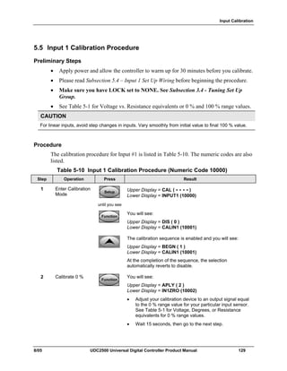
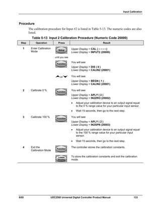
4.5.1 Annunciators
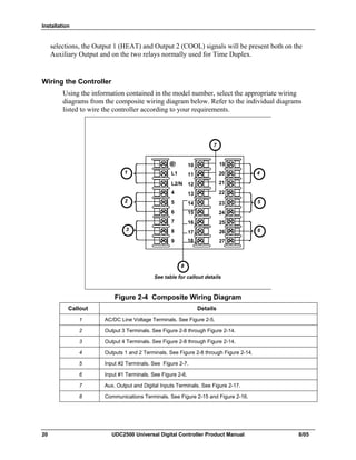
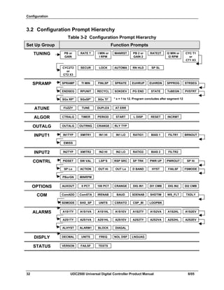
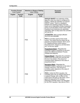
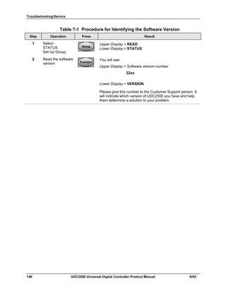
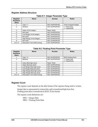
The following annunciator functions have been provided to help monitor the controller:
Table 4-2 Annunciators
Annunciator Indication
ALM 1 2 A visual indication of each alarm
Blinking 1 indicates alarm latched and needs to be acknowledged (by
pressing the RUN/HOLD key before extinguishing when the alarm
condition ends
OUT 1 2 A visual indication of the control relays
A or M A visual indication of the mode of the controller (Dual display model only)
A—Automatic Mode
M—Manual Mode
[None], F or C A visual indication of the temperature units
[None]—No temperature unit annunciator
F—Degrees Fahrenheit
C—Degrees Celsius
L or R A visual indication of setpoint being used
L— Local Setpoint is active
R— RSP or LSP 2 is active
The upper display is used to show other annunciator functions
TUNE—Accutuning in progress
RUN—SP Program in progress
HOLD—SP Program on hold
CSP—Controlling to the Computer Setpoint
LOOPBK—Loopback Test running](https://image.slidesharecdn.com/honeywelludc2500-130826022228-phpapp02/85/Honeywell-udc-2500-99-320.jpg)
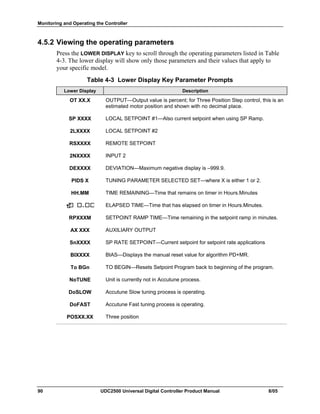
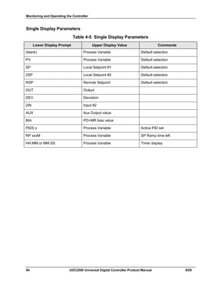
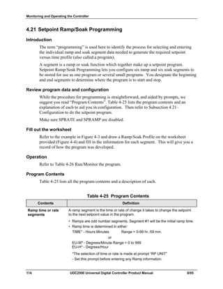
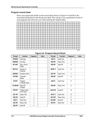
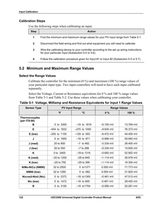

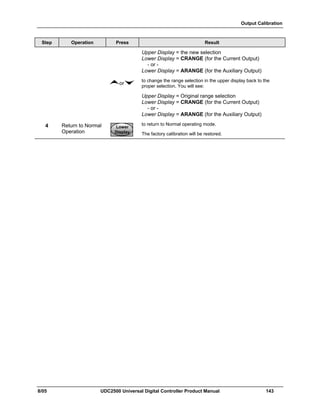
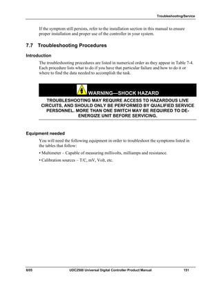
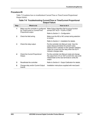
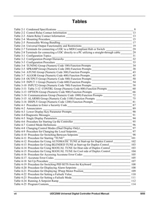
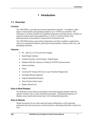
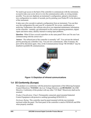
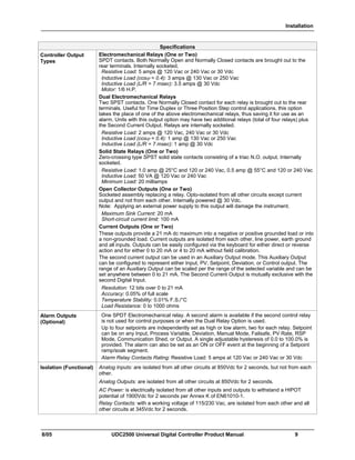
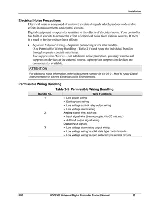
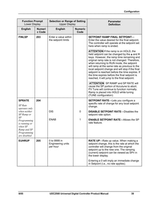
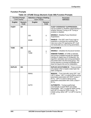
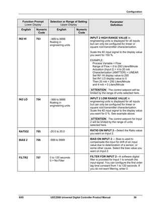
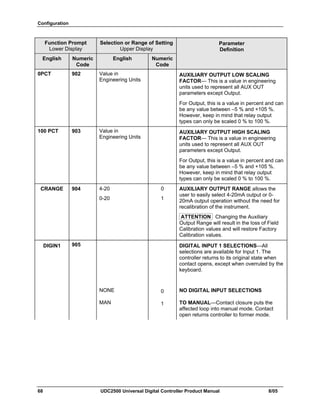
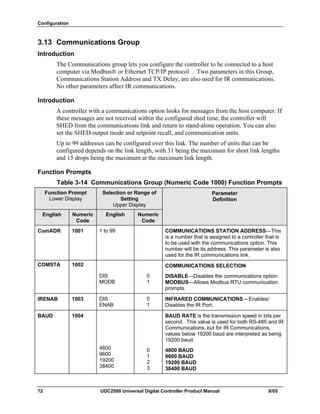
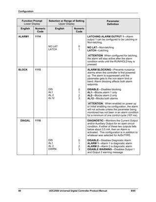
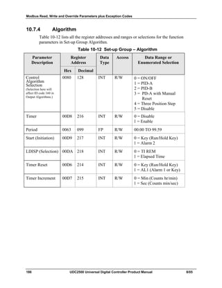
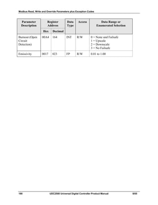
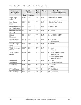
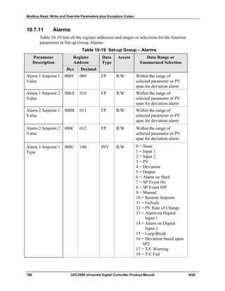
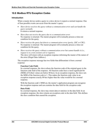
![Troubleshooting/Service
8/05 UDC2500 Universal Digital Controller Product Manual 157
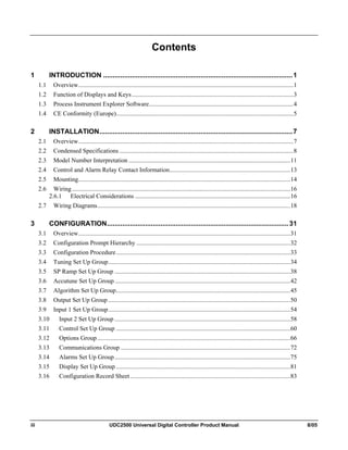
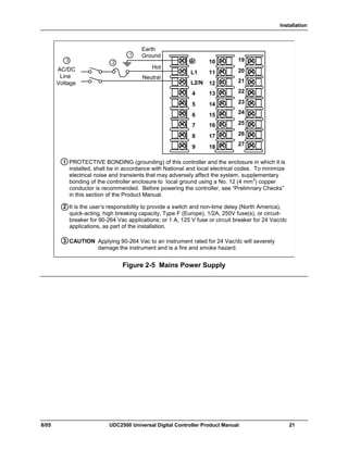
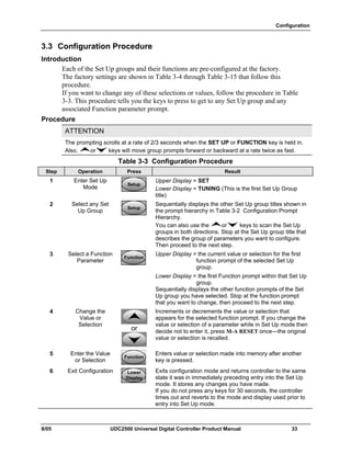
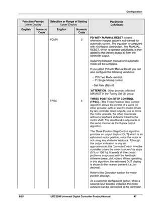
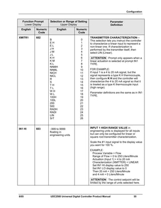
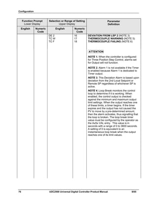
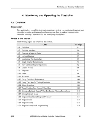
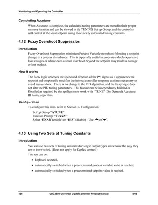
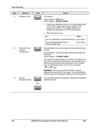
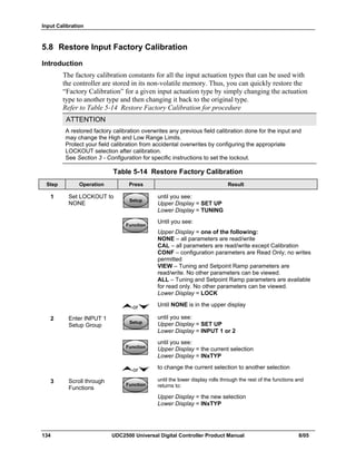
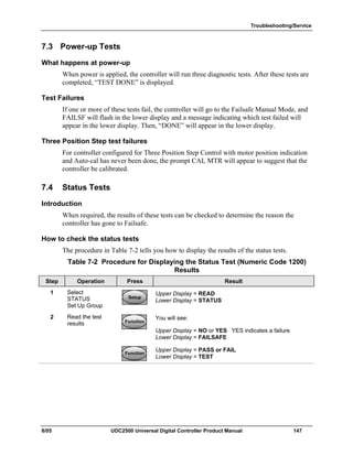
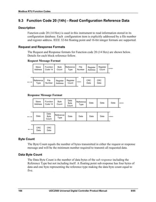
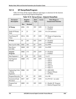
Procedure #7
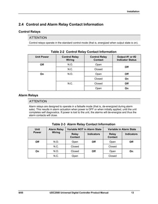
Table 7-11 explains how to troubleshoot a Keyboard failure.
Table 7-11 Troubleshooting a Keyboard Failure
Step What to do How to do it
1 Make sure the keyboard is
connected properly to the
MCU/output and power/input
boards.
Withdraw the chassis from the case
and visually inspect the connection.
2 Controller Keyboard or specific keys
may be LOCKED OUT via the
security code.
Use your four-digit security code
number to change the lockout level.
Refer to Section 3 – Configuration.
3 Run the keyboard test. Press the [SET UP] key and hold in,
then press the [FUNCTION] key at the
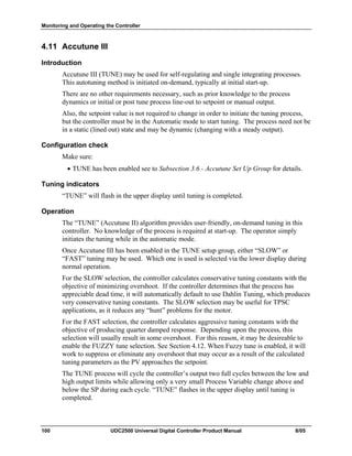
same time. The controller will run a
display test. Then you will see:
TRY ALL
Lower Display
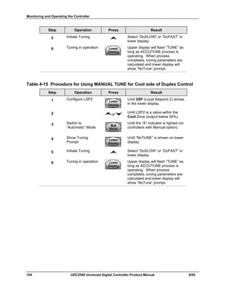
KEYS
Upper Display
Press each key. If it works, the key
name will appear in the lower display.
4 Replace the display/keyboard if any
keys do not function.
Refer to “Parts Replacement
Procedures” in this section.](https://image.slidesharecdn.com/honeywelludc2500-130826022228-phpapp02/85/Honeywell-udc-2500-167-320.jpg)
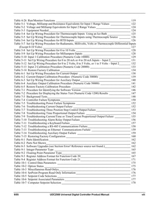
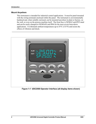
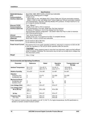
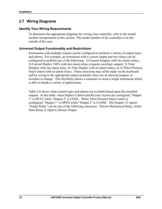
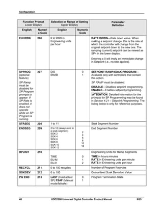
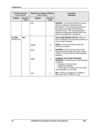
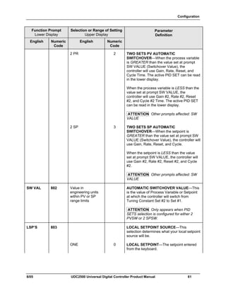
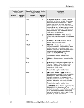
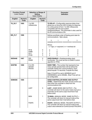
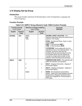
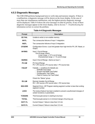
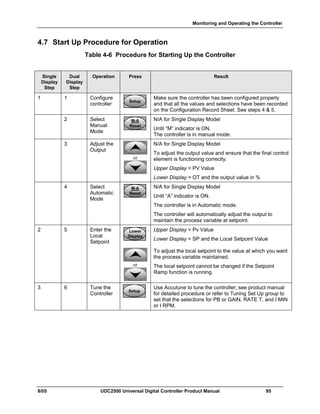
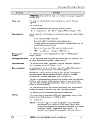
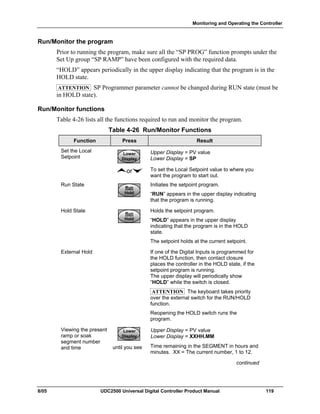
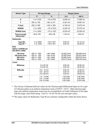
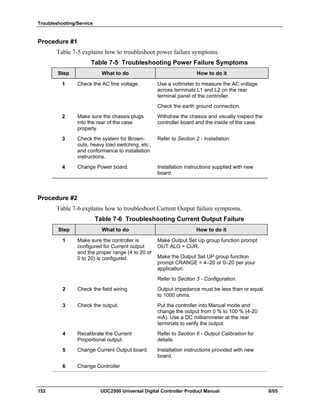
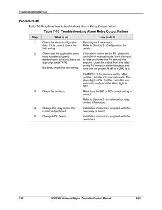
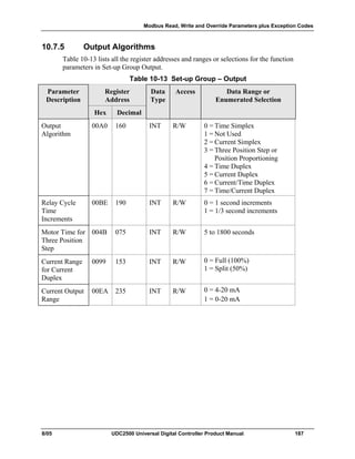
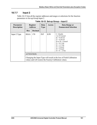
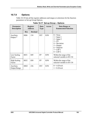
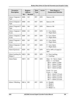
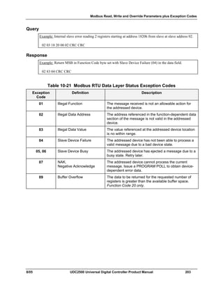
![Troubleshooting/Service
158 UDC2500 Universal Digital Controller Product Manual 8/05
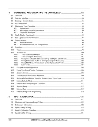
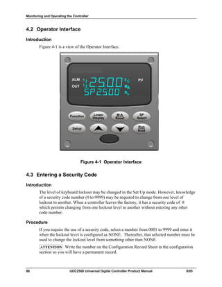
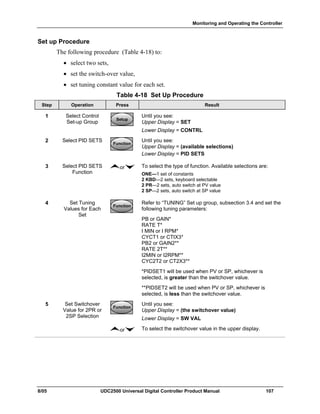
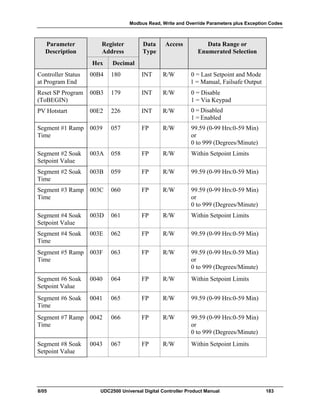
Procedure #8
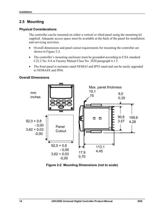
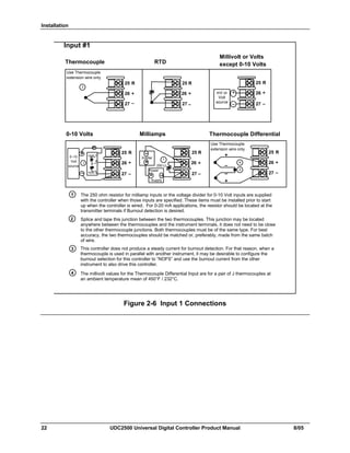
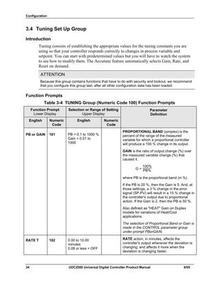
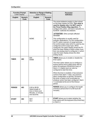
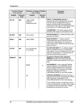
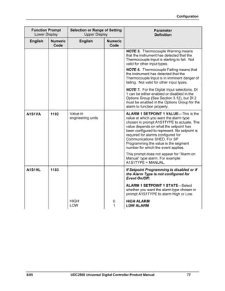
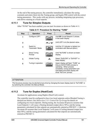
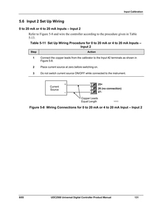
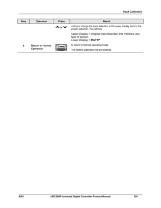
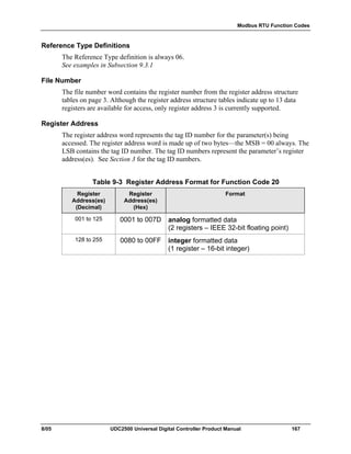
Table 7-11 explains how to troubleshoot a Communications failure
Table 7-12 Troubleshooting a RS-485 Communications Failure
Step What to do How to do it
1 Check the Address Number,
ComState and Baud Rate settings.
See Section 3.13.
2 Check the field wiring and
termination resistor.
Using an ohm meter, check the resistance across
the communications rear terminals. See Section
2.7 for wiring diagrams.
3 Make sure the Communications
Printed Wiring Board is installed
properly in the controller.
Withdraw the chassis from the case and inspect the
board. See the exploded view (Figure 8-1) for
location of the board. Return the chassis to the
case.
4 Determine if the Communications
board is faulty by running a LOCAL
LOOPBACK TEST.
If the test fails, replace the board.
If the test passes, the problem is
most likely elsewhere in the
communications network.
Disconnect the communications cable from the rear
terminals. Run the Local Loopback Test.
Press [SET UP] until you see:
COM
Lower Display
SET UP
Upper Display
Press [FUNCTION] until you see:
LOOPBACK
Lower Display
DISABLE
Upper Display
Press or you will see:
LOOPBACK
Lower Display
ENABLE
Upper Display
The test will run until the operator disables it here.](https://image.slidesharecdn.com/honeywelludc2500-130826022228-phpapp02/85/Honeywell-udc-2500-168-320.jpg)
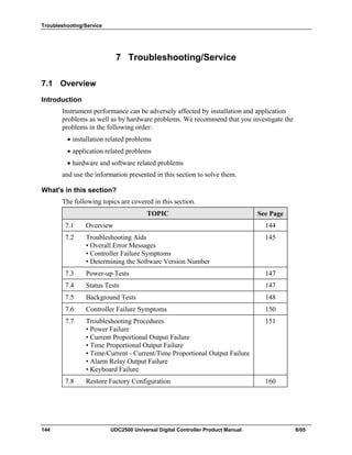
![Troubleshooting/Service
160 UDC2500 Universal Digital Controller Product Manual 8/05
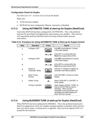
6 Change Controller
7.8 Restoring Factory Configuration
Introduction
This procedure restores the configuration of the instrument back to the Factory Settings
per Section 3.16.
ATTENTION: Restoring the factory configuration overwrites all user-entered
configuration changes. This procedure cannot be undone, it is a one-way process.
Table 7-15 explains how to restore Factory Configuration.
Table 7-15 Restoring Factory Configuration
Step What to do
1 Turn off the power to the instrument for at least five seconds.
2 Turn the power back on and simultaneously press the “FUNCTION” and
keys. This must be done while “TEST DONE” is being displayed.
3 If step 2 was performed correctly, the instrument will now display “UDC”
[Upper] “UPDATE” [Lower].
4 Press the FUNCTION Key. The instrument will now display “DIS” [Upper]
“RESTORE” [Lower].
5 Press the key. The instrument will now display “CFG” [Upper]
“RESTORE” [Lower].
6 Press the FUNCTION Key. The instrument will now display “DOIN”
“RESTORE”
7 When the instrument finishes the restore operation, it automatically resets
itself and restarts in the product mode. The instrument configuration will
now be the same as it was when the instrument left the factory and all user-
entered configurations since that time have been overwritten.](https://image.slidesharecdn.com/honeywelludc2500-130826022228-phpapp02/85/Honeywell-udc-2500-170-320.jpg)


This document provides an overview and instructions for installing, configuring, operating, and troubleshooting the UDC2500 Universal Digital Controller. It describes the controller's displays, keys, software, mounting considerations, wiring diagrams, configuration groups and parameters, operating modes, setpoints, alarms, and tuning functions. Safety symbols are defined that are used in the document.


